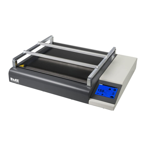
Pace PH 100 User manual

- 1 -
PH 100
Low Profile IR Pre-heater
Operations Manual
Manual Number 5050-0587 Rev. C
Applies to
8007-0572 PH 100 115-120VAC, 50/60Hz
8007-0573 PH 100E 230VAC, 50/60Hz
With Program Version 2.4

- 2 -
PACE PH 100 Table of Contents
PH 100 Identification/Overview ........................................................................................- 1 -
Packaging Contents ......................................................................................................- 2 -
Specifications.................................................................................................................- 2 -
Safety Precautions ............................................................................................................- 3 -
Board Holder Set-up..........................................................................................................- 4 -
Preheating Basics .............................................................................................................- 4 -
System Operation..............................................................................................................- 5 -
Main Menu ......................................................................................................................- 5 -
Icon Bar Explanations ...................................................................................................- 6 -
Device Settings Menu....................................................................................................- 6 -
Heater Settings Menu ....................................................................................................- 8 -
Preheat Cycles............................................................................................................- 9 -
Tips and Troubleshooting...............................................................................................- 10 -
Replacement Parts.......................................................................................................- 10 -
PACE Worldwide Limited Warranty ...............................................................................- 10 -
Contact Information ........................................................................................................- 11 -

- 1 -
PH 100 Identification/Overview
Front/Top View
1
Magnetic Feet (large shown)
2
Aluminum Board Holder Rails
3
Steel Board Holder Supports
4
Resistive Touch Screen Control Panel
5
Ceramic Glass Heat Diffuser
1
Power Switch
2
Fuse Socket: 6.3x32 mm
3
USB 2.0 Port
4
Top Sensor
K-type Thermocouple connector
5
Bottom Sensor
K-type Thermocouple connector
6
Power Cord Receptacle
1
2
3
4
1
2
3
6
5
4
Rear panel
NOTE: Use only Slo-Blo fuses in this unit. 15A for 120V units / 10A for 230V units.
5

- 2 -
Packaging Contents
Description
Qty.
PH 100 Preheater
1
Power Cord
1
K-type Thermocouple
2
Aluminum bars, notched for holding board
13 in. (330 mm) long
2
Steel bars, board holder support rails,
12.125 in (307 mm) long
2
Small magnetic feet
4
Large magnetic feet
4
Specifications
Part Number
(Domestic)- 8007-0572
(Export)- 8007-0573
Dimensions
3 in. H (w/ board holder, no feet) x 17 in. W x 14 in. D
(76.2 mm x 381 mm x 457.2 mm)
Weight
18.05 lbs (8.2 kg)
Power Requirements
115 VAC, (Domestic), 14 Amps (1600W)
230 VAC, (Export), 7 Amps (1600W)
Pre-Heaters
4 x Ceramic Infrared (IR) Heaters in 2 zones
Control
Resistive Touchscreen
PC Board Size
11.75 in (298.45 mm) D x 11.75 in (298.45) W
(width is open ended when using single sided pcb)
RoHs
YES
Calibration
NO
Temp Range
20°C - 200°C or 68°F - 392°F

- 3 -
Safety Precautions
1. NEVER touch the display with a hot soldering iron or other hot tools.
2. Wait one hour after unpacking the device to allow any condensation built up during transport to
dissipate.
3. Do not expose the device to water or other moisture.
4. The PH 100 Preheater must only be used indoors near a suitable power source. Avoid using extension
cords. When not in use, store unit in a clean, dry place.
5. Place the PH 100 Preheater device on a solid, hard, dry, stable surface with good ventilation. Do not
place the device on damaged or heat-sensitive surfaces. Leave space around the device and
underneath (min. 20 cm) for proper ventilation.
6. WARNING: ALWAYS let the PCB cool down before touching it after heating. After Power Off, the device
will take up to 30 minutes to cool down. Wait for the device to cool down before touching the glass-
ceramic heating plate. Always turn off the system and verify it has cooled down before leaving it
unattended. The heating plate is hot and may cause burn injuries. ALWAYS use heat-insulated gloves.
7. The PH 100 MUST ONLY be used for preheating PCBs for soldering and rework operations.
8. DO NOT use the device if the glass-ceramic heating plate is cracked, or otherwise damaged or broken.
9. DO NOT place PCB’s (or anything else) directly onto the glass-ceramic heating plate.
10. ALWAYS mount the PCB to be preheated onto the PCB holder.
11. PH 100 Preheater should only be used by trained personnel.
12. DO NOT use the device near flammable materials. DO NOT store flammable materials near the device.
ALWAYS consult the MSDS (Material Safety Data Sheet) of materials to check their flammability.
13. DO NOT attempt to modify or repair the device yourself. If a fault develops, contact us at
support@paceworldwide.com (USA) or sales@paceworldwide.com (Europe). The case is sealed by a
hologram label. If this is damaged, the warranty is automatically voided.
14. ALWAYS check that the power cable is not damaged before every use.
15. PH 100 Preheater MUST ONLY be connected to a properly grounded (earthed) power supply of the
proper voltage and frequency (PH 100 120VAC, 50/60 Hz; PH 100E 230VAC 50/60 Hz). Always check
that the ground (earth) is working correctly.
16. Minimum/Maximum ambient temperatures: Min = +5°C (41°F); Max = +40°C (104°F)
17. Humidity Limits: Up to 80% relative humidity at 31°C, which decreases linearly between 31°C and 40°C,
to a maximum of 50% relative humidity. Maximum operating altitude above sea-level 2000m (6562 ft.).
18. During soldering and rework processes, toxic/noxious fume emissions may be released. ALWAYS use
Fume Extraction or exhaust ventilation as specified in the MSDS of the solder, flux and solvent materials
being used. As with all soldering devices, particularly in industrial use, it may be necessary to measure
the emissions, which should be done by an expert.
19. DO NOT place the magnetic PCB holder rails or magnetic feet on a hot surface as they may become
demagnetized.
20. The power outlet MUST be easily reachable to cut off the power in case of emergency. The power can
only be cut by unplugging the device from the power outlet or unplugging the cord from the unit. Even
after you have turned off the device using the ON/OFF switch, it is still connected to live power.

- 4 -
Features
3.5 inch resistive touch screen.
11.8 inch (300mm) square, glass-ceramic heating surface.
Four individual IR heating elements arranged in two zones for a total of 1600W, can also be
limited to 800W total across all four heaters.
Closed loop temperature control using one of three different sensors.
Front and Back heating zone cans independently be adjusted ±90°F (50°C) from the set
temperature. (When using the internal sensor.)
Built-in timer function with alarm.
Auto-Off timer function for safety and convenience.
Included adjustable height magnetic board holder.
Board Holder Set-up
The board holder for the PH 100 can be set-up at three different heights to allow for more or less clearance over
the heating plate, or to fit under other equipment. The lowest setting is achieved by gently placing the brightly
polished steel rails, magnet side down, directly on the gray casing to the left and right sides of the glass-ceramic
heating plate. Then place the satin-finished aluminum rails onto the steel rails, with the notched corners facing
inward and the magnets facing down. At this level the bottom of a board sitting in the notches of the board
holder rails, would be 0.375 inches (9.525mm) above the heating plate.
To increase the height of the board holder and provide more clearance, two different sets of magnetic feet have
been included. To prevent damage to the glass-ceramic plate, it is best to remove the aluminum board holder
rails completely before adding the feet underneath the steel support rails. Each foot is notched on one end for
the steel support rails to set into, and the bottom is magnetic with a Teflon pad to help prevent scratches. The
small feet give a clearance of 0.875 inches (22.25mm) from the bottom of a board sitting in the holder, and the
large feet provide clearance of 1.4375 inches (36.513mm).
Preheating Basics
Preheating of a printed circuit assembly is normally required in the repair process whenever any of the following
conditions exist.
Epoxy Glass substrate with 4 or more layers.
The board has large ground planes
The substrate is made of ceramic, polyimide, or other high heat dissipating material.
The board has large metal heat sinks or other items with large thermal mass.
The use of preheating on these materials improves the soldering process by;
Minimizing the time exposed to high temperatures before the solder flows.
Increases efficiency of point heating by overcoming heat dissipation.
Minimizing reflow of surrounding components due to the combination of all of the above.
Minimizing thermal shock to surrounding components by helping to normalize temperatures across the
board.
The assembly being heated must be allowed to soak for a length of time to ensure the desired temperature has
sufficiently saturated throughout the mass. Commonly used preheat temperatures for PCB are 212°F (100°C)
and 248°F (120°C).

- 5 -
System Operation
Main Menu
1. Set Temperature: Set the temperature by tapping the number. A numeric keyboard will appear that will
allow you to set the temperature from 20 - 200°C (68 - 392°F). Temperature can also be set by tapping
the + or - buttons.
2. Actual Temperature/Offset: Actual temperature shows internal temperature of the heater. Offset
shows how much the front and back heaters have been adjusted away from the Set Temperature. If the
unit is set to use the top or bottom sensor as active, this area will be blank.
3. Temperature Curve: The straight thin line indicates the Set Temperature. The bold line shows the
actual temperature reading for the currently selected sensor over the last 2 minutes.
4. Top Sensor: Shows the Top Sensor temperature when a thermocouple is in use. When not in use, will
display “N.C.” (Not Connected).
5. Bottom Sensor: Shows the Bottom Sensor temperature when a thermocouple is in use. When not in
use, will display “N.C.” (Not Connected).
6. Icon Bar: Displays key operational information icons during use. See page 6 for icon explanations.
7. Password/Screen Lock Button: Tap this button to lock the screen. On the Icon Bar a lock appears.
Tap the button again and enter password to unlock.
8. Device Settings Menu Button: Tap this button to open main Device Settings Menu screen. See page 8
for full explanations.
9. Power Meter Button: Tap the button to set the power level of the preheater. Options are 1600W or
800W. The meter shows the duty cycle or power level at which the heater is currently operating.
10. Soft Shut-Off: Tapping this button will turn the machine off but keep the internal cooling fans on.
Shutting the unit off via the circuit breaker on the back causes complete power loose to the unit and
may cause overheating as the residual heat built up inside the machine leaks out into the surrounding
circuitry.
11. Increase (+) Temperature Button: Tap button to increase set temperature (hold for quick- set).
12. Decrease (-) Temperature Button: Tap button to decrease set temperature (hold for quick- set).
1
2
3
4
5
8
6
7
12
9
11
10

- 6 -
Icon Bar Explanations
The icon bar can tell us several different things at a quick glance. The icon at right shows the
internal cooling fan is operational and should always be present.
One of the following three icons will also always be present in the top right corner.
Indicates the internal sensor is currently active.
The Bottom Sensor is active when this icon is displayed.
Indicates the Top Sensor is active.
This icon only shows up when the power limiter has been activated, and designates the unit as
currently operating at half its normal capacity, 800 watts. If this icon is not present, the unit can
make use of the entire 1600 watt capacity.
Finally, if the screen is locked using the password feature a lock will appear in the icon bar area.
Device Settings Menu
Selecting the gear icon brings up this screen. Tap the arrow in the upper right hand corner to return to the
main menu.

- 7 -
Device Settings continued…
1. Mode -- There are two options; User
and Advanced. Change modes by
tapping this square. See the following
section Heater Settings Menu for
additional information.
2. Swap -- This icon will allow you to
rearrange items on the Main Menu
screen. Tapping this block brings up
the main display, then select the item
you wish to move followed by the
square you want it to move to.
3. Main Menu Color -- The PH 100 touch screen display offers many color variations with lots of adjustability.
This option allows the user total control over individual buttons on the main menu. Touching this button
brings up the Main Menu again, but notice the icon bar is replaced with “Main Menu Color Settings”.
Tapping a button in the Main Menu Color Settings screen brings us to the following screen.
The color is changed using the RGB color model. We can change the color of the button at idle, the color
when it’s pressed, as well as the color of the icon.
Tapping the plus or minus in each column adjusts the amount of
red, green, or blue (in that order) for the chosen item. The empty
square in the lower right corner will display the resulting color.
Tapping the arrow returns to the Device Settings menu without
making any changes.
Tapping the check mark saves the changes and returns to the
settings menu.
4. Back Arrow -- Tapping this icon returns to the Main Menu
5. Auto-Off -- The auto-off screen presents three options. Tap the Shutdown Timer button to turn the Auto-Off
function on or off. How long the unit will remain on by default is 2 hours. This can quickly be increased to
preset times of 4 or 8 hours. The timer can be set to a custom value anywhere between 1 to 24 hours in 1
hour increments by tapping the NumPad option.

- 8 -
Device Settings continued…
6. Welcome -- Tapping this button will toggle on/off
the PACE splash screen and safety precautions
that come up when the unit is first turned on.
7. Volume –This square is used to cycle through the
three sound levels; low, high, or off.
8. Heater Settings –This button opens the heater
settings menu. See the following section for more
information. This button is also present on the main menu screen and appears again here for convenience.
9. Color Profile -- The PH 100 has 9 preset color profiles to choose from. Each profile is fully adjustable and
will also remember any specific changes made to the Main Menu using the Main Menu Color option.
10. Information -- This is where you can find out which version of software is currently installed on your PH 100.
This screen also provides a reset button which will restore the factory default settings for the currenttly
installed software version.
11. Power Settings –This square provides the same function as tapping the power meter on the Main Menu, it
provides access to the power limiting function. Options are 1600 watts or 800 watts.
12. Temperature Scale –Tapping here will switch the PH 100 between Celsius and Fahrenheit.
Heater Settings Menu
There are two heater settings menus, selectable in the Device Settings as Mode: User and Mode: Advanced.
User mode is very straight forward and only allows selection of input sensor for the closed loop temperature
monitoring.
To the left is the Heater Settings Menu with the PH 100 set to
User Mode. Tapping the arrow goes back to the previous
screen. Tapping the Control button will cycle through the
three available settings; Internal, External Top Sensor and
External Bottom Sensor.
The PH 100 will actively monitor the selected sensor and will
continuously adjust power to the heaters, bringing the
temperature at the sensor location up to the Set
Temperature.
Sensor selection and placement are important for safe and
accurate heating!

- 9 -
Heater Settings continued…
To the right we have the Advanced Mode screen.
The first two columns are for adjusting the offset of
the front and/or back halves of the PH 100. Each
half can be adjusted to be 90°F (50°C) higher or
lower than the set point. This option is only
available when using the PH 100’s internal sensor.
If either of the external sensors are the actively
monitored sensor, the plus and minus buttons will
be missing from this screen.
In the far right column, we have the ability to select
how precisely the heaters inside the unit are
controlled. The options for “Heat up” are normal
and fine and are switched between the two just by
tapping the square.
Preheat Cycles
From the advanced mode heater settings
screen, we can run timed heating cycles. This
is accomplished by entering a time and
temperature in the associated boxes.
Tapping Preheat Time will bring up a number
pad for entering a time anywhere from 0 to 60
minutes. After entering a time, press the
checkmark to exit and start the timer. To
change an incorrect number, press the arrow
button to backspace. Continue pressing the
arrow to clear any entries and exit without
setting a timer.
After exiting the Preheat Time entry screen, the
timer begins and the unit will attempt to reach
the temperature set in the Preheat Temp box if
something other than 0 was entered. At the end
of the timer an alarm will sound and the unit will
return to the previously set temperature automatically.
During the timed cycle, the Set Temp area of the home screen will display the Preheat temp. During the cycle,
the temperature on the main screen will be locked. To change the temperature without canceling the timer, you
must come back to the heater settings screen and adjust the Preheat temp. Once the timed cycle is finished, an
alarm will sound and the unit will return to the previously set temperature.
To cancel the timer, you must again come back to the heater settings screen and enter a time of 0.

- 10 -
Tips and Troubleshooting
To help avoid damage to boards and components, always use the external thermocouple sensors.
Even if the unit is actively using the internal sensor, the external sensors can still provide valuable
information about the temperature of various parts.
When working with a new or different PCB, try using the Bottom Sensor as the active. This should give
the most accurate board temperature on most assemblies, with the least chance of overshooting the
desired temperature and damaging something.
The lock feature has the password of PACE as it is spelled out with a standard North American phone
or any other phone keypad which meets the International Telecommunication Union standards.
The software can be updated using a USB memory stick. It is recommended the USB stick be smaller
than 1 GB and be in the FAT or FAT32 format but others may work due to differences in manufacturing.
The unit does not turn on? Check that the power cord is fully seated in the unit and an active power
source of the appropriate voltage for your machine. Also ensure the fuses is are good and have not
blown. Use only Slo-Blo fuses in this unit. 15A for 120V units / 10A for 230V units.
Replacement Parts
10A Time-Lag Fuse (for 230v)
1159-0281-P3
15A Time-Lag Fuse (for 115v)
1159-0282-P3
Thermal Fuse Harness
1159-0283-P1
PACE Worldwide Limited Warranty
PACE warrants to the first user that products manufactured by it and supplied hereunder are free of defects in
materials and workmanship for a period of one (1) year from the date of receipt by such user. This
Warranty as applied to blowers and motor pumps is limited to a period of one (1) year. Monitors,
computers and other brand equipment supplied, but not manufactured by PACE, are covered under their
respective manufacturer’s warranty in lieu of this Warranty.
This warranty does not cover wear and tear under normal use, repair or replacement required as a result of
misuse, improper application, mishandling or improper storage. Consumable items such as tips, heaters,
filters, etc., which wear out under normal use are excluded. Failure to perform recommended routine
maintenance, alterations or repairs made other than in accordance with PACE’s directions, or removal or
alteration of identification markings in any way will void this warranty. This warranty is available only to the
first user, but the exclusions and limitations herein apply to all persons and entities.

- 11 -
PACE MAKES NO OTHER WARRANTY, EXPRESS OR IMPLIED, AND MAKES NO WARRANTY OF
MERCHANTABILITY OR FITNESS FOR A PARTICULAR PURPOSE.
PACE will, at PACE’s option, repair or replace any defective products at its facility or other location approved
by it at no charge to user, or provide parts without charge for installation by the user in the field at user’s
expense and risk. User will be responsible for all costs of shipping equipment to PACE or other location
for warranty service.
EXCEPT FOR THE REMEDY ABOVE DESCRIBED, UNLESS OTHERWISE REQUIRED BY APPLICABLE
LAW, PACE WILL HAVE NO OTHER OBLIGATION WITH REGARD TO ANY BREACH OF WARRANTY
OR OTHER CLAIM WITH RESPECT TO THE PRODUCTS, OR LIABILITY FOR ANY DIRECT,
INDIRECT, CONSEQUENTIAL, OR INCIDENTAL LOSS OR DAMAGE CAUSED BY OR OCCURRING IN
CONNECTION WITH ANY OF THE PRODUCTS.
Warranty service may be obtained by contacting the appropriate PACE Company or local Authorized PACE
distributor as set forth below to determine if return of any item is required, or if repairs can be made by the
user in the field.
Defective products may not be returned to PACE without a Service Authorization (“SA”) Number.
Any warranty or other claim with respect to the products must be made in writing delivered to PACE
(or local Authorized PACE distributor for Buyers outside the USA and the United Kingdom) within a
reasonable time of the expiration date of this warranty with sufficient evidence of purchase and date of
receipt, otherwise user’s rights under this warranty shall be deemed waived.
PACE, Incorporated retains the right to make changes to specifications contained herein at any time, without
notice.
The following are registered trademarks and/or service marks of PACE, Incorporated, Laurel,
Maryland, USA and may be used to identify genuine PACE products or services.
Arm-Evac®, Flo-D-Sodr®, Mini-Wave®, PACE®, SensaTemp®, Snap-Vac®, SODRTEKSM,
Sodr-X-Tractor®, Thermo-Drive®, ThermoFlo®, ThermoJet®, ThermoTweez®, TOOLNETSM,
VisiFilter®,PermaGround®. IntelliHeat®.
Additional copies of this manual or other PACE literature may be obtained from: http://paceworldwide.com
Contact Information
Pace Incorporated
346 Grant Road
Vass, North Carolina 28394
Tel: (877) 882-PACE
Tel: (910) 695-7223
Fax: (910) 695-1594
Email: [email protected]
Pace Europe
11 Holdom Avenue
Bletchley, Milton Keynes,
United Kingdom, MK1 1QU
Tel: 011 44 1908 277666
Fax: 011 44 1908 277777
Other manuals for PH 100
1
This manual suits for next models
3
Table of contents
Other Pace Heater manuals