MHS Boilers DYD24/18 User manual

LO
HI OFF
ON
I
G
N
MODEL DYD24/18
Natural Gas or Propane/LPG
Control Type: Manual or Millivolt
UNVENTED GAS LOG HEATER OR
VENTED DECORATIVE APPLIANCE
INSTALLATION AND OPERATING INSTRUCTIONS
READ BEFORE INSTALLING. SAVE THESE INSTRUCTIONS
This is an unvented gas-fired heater.
It uses air (oxygen) from the room
in which it is installed. Provisions for
adequate combustion and ventilation
air must be provided. See page 7.
WARNINGS
If the information in this manual is not followed
exactly, a fire or explosion may result causing
property damage, personal injury or loss of life.
– Do not store or use gasoline or other flammable
vapors and liquids in the vicinity of this or any
other appliance.
– WHAT TO DO IF YOU SMELL GAS
• Do not try to light any appliance.
• Do not touch any electrical switch; do not use
any phone in your building.
• Immediately call your gas supplier from a
neighbor's phone. Follow the gas supplier's
instructions.
• If you cannot reach your gas supplier, call the
fire department.
– Installation and service must be performed by
a qualified installer, service agency or the gas
supplier.
WARNINGS

2 65D0001
CONTENTS
Important Safety Information .......................... 3
Getting Started .................................................. 5
Product Features and Specifications ............. 6
General Installation Information ..................... 7
Codes ........................................................... 7
Adequate Combustion and
Ventilation Air .............................................. 7
Fireplace and Hearth Dimensions .................. 9
Placement in a Fireplace with a Restrictive
Barrier ........................................................ 10
Clearances and Height Requirements ...........11
Floor Clearance .............................................. 14
Fireplace Preparation ..................................... 15
Installing Vented Appliance ........................... 16
Connecting the Gas ........................................ 17
Checking Gas Pressure ................................. 18
Electrical Wiring (Millivolt) ............................. 19
Log Placement ................................................ 21
Flame Appearance .......................................... 22
Checking Burner Flame ................................. 23
Operating Instructions ................................... 23
For Your Safety Read Before Lighting .... 24
Manual Control Lighting Instructions ..... 25
To Turn Off Gas to Heater ......................... 25
Millivolt Control Lighting Instructions .... 26
To Turn Off Gas to Heater ......................... 26
Match Lighting Instructions ..................... 27
Cleaning and Servicing .................................. 27
Troubleshooting ............................................. 28
Illustrated Parts Breakdown .......................... 30
Replacement Parts ......................................... 31
Warranty ...........................................Back Cover

65D0001 3
8. For propane/LP insert, do not place propane/LP supply
tank(s) inside any structure. Locate propane/LP supply
tank(s) outdoors. To prevent performance problems, do not
use propane/LP fuel tank of less than 100 lbs. capacity.
9. The installation must conform with local codes or, in
the absence of local codes, with the National Fuel Gas
Code, ANSI Z223.l/NFPA54.
10. This unit complies with ANSI Z21.11.2b.2004 Unvented
Heaters and also complies with ANSI Z21.60-1996
Decorative Vented Appliances for Solid Fuel Burning
Fireplaces. State and local codes may only allow opera-
tion of this appliance in a vented configuration. Check
your state or local codes. For vented operation, see Vented
Instructions in this manual.
11. Do not install the heaters in a bathroom or bedroom.
12. Correct installation of the ceramic fiber logs, proper
location of the heater, and annual cleaning are neces-
sary to avoid potential problems with sooting. Sooting,
resulting from improper installation or operation, can
settle on surfaces outside the fireplace. See log placement
instructions for proper installation.
INSTALLER
Please leave these instructions with the owner.
OWNER
Please retain these instructions for future reference
.
IMPORTANT SAFETY INFORMATION
IMPORTANT
Read these instructions carefully before installing or trying to operate this vent-free gas heater.
1. Due to high temperatures, the appliance should be
located out of traffic and away from furniture and
draperies.
2. Children and adults should be alerted to the hazard
of high surface temperature and should stay away to
avoid burns or clothing ignition.
3. Young children should be carefully supervised when
they are in the same room with the appliance.
4. Do not place clothing or other flammable material on
or near the appliance.
5. Any safety screen or guard removed for servicing an
appliance, must be replaced prior to operating the
heater.
6. Installation and repair should be done by a qualified
service person.
7. To prevent malfunction and/or sooting, an unvented
gas heater should be cleaned before use and at least
annually by a professional service person. More
frequent cleaning may be required due to exces-
sive lint from carpeting, bedding materials, etc. It is
imperative that control compartments, burners and
circulating air passageways be kept clean.
• Any change to this heater or its controls can be dangerous.
• Improper installation or use of the heater can cause serious injury or death from fire,
burns, explosion or carbon monoxide poisoning.
• Do not allow fans to blow directly into the fireplace. Avoid any drafts that alter burner
flame patterns.
• Do not use a blower insert, heat exchanger insert or other accessory, not approved for
use with this heater where applicable.
WARNING
CARBON MONOXIDE POISONING: Early signs of carbon monoxide poisoning are similar to the flu with head-
aches, dizziness and/or nausea. If you have these signs, the insert may not have been installed properly. Get fresh air at
once! Have the insert inspected and serviced by a qualified service person. Some people are more affected by carbon
monoxide than others. These include pregnant women, people with heart or lung disease or anemia, those under the
influence of alcohol, and those at high altitudes.
Propane/LP gas and natural gas are both odorless. An odor-making agent is added to each of these gases. The odor
helps you detect a gas leak. However, the odor added to these gases can fade. Gas may be present even though no
odor exists.
Continued on page 4
4 65D0001
IMPORTANT SAFETY INFORMATION
This appliance may be installed in an aftermar-
ket, permanently located, manufactured (mobile)
home, where not prohibited by local codes.
This appliance is only for use with the type of gas
indicated on the rating plate. This appliance is not
convertible for use with other gases.
Continued from page 3
13. Avoid any drafts that alter burner flame patterns. Do not
allow fans to blow directly into fireplace. Do not place
a blower inside burn area of firebox. Ceiling fans may
create drafts that alter burner flame patterns. Sooting and
improper burning will occur.
14. Caution: Candles, incense, oil lamps, etc. produce
combustion byproducts including soot. Vent-free appli-
ances will not filter or clean soot produced by these types
of products. In addition, the smoke and/or aromatics
(scents) may be reburnt in the vent-free appliance which
can produce odors. It is recommended to minimize the
use of candles, incense, etc. while the vent-free appli-
ance is in operation.
15. This is an unvented gas-fired heater. It uses air (oxygen)
from the room in which it is installed. Provisions for ad-
equate combustion and ventilation air must be provided.
See page 7.
16. Keep room area clear and free from combustible materi-
als, gasoline and other flammable vapors and liquids.
17. Unvented gas heaters are a supplemental zone heater.
They are not intended to be a primary heating appliance.
Water vapor produced by an unvented heater can create
moisture problems in a home when operated for extended
periods of time.
18. During manufacturing, fabricating and shipping, various
components of this appliance are treated with certain
oils, films or bonding agents. These chemicals are not
harmful but may produce annoying smoke and smells
as they are burned off during the initial operation of the
appliance; possibly causing headaches or eye or lung
irritation. This is a normal and temporary occurrence.
The initial break-in operation should last two to three
hours with the burner at the highest setting. Provide
maximum ventilation by opening windows or doors to
allow odors to dissipate. Any odors remaining after this
initial break-in period will be slight and will disappear
with continued use.
19. Input ratings are shown in BTU per hour and are for
elevations up to 2,000 feet. For elevations above 2,000
feet, input ratings should be reduced 4 percent for each
1,000 feet above sea level. See the National Fuel Gas
Code.
20. The heater and its individual shutoff valve must be
disconnected from the gas supply piping system during
any pressure testing of that system at test pressures in
excess of 1/2 psig (3.5 kPa).
21. The heater must be isolated from the gas supply piping
system by closing its individual manual shutoff valve
during any pressure testing of the gas supply piping
system at test pressures equal to or less than 1/2 psig
(3.5 kPa).
22. Do not use this room heater if any part has been under
water. Immediately call a qualified service technician
to inspect the room heater and to replace any part of the
control system and any gas control which has been under
water.
23. This appliance must not be used with glass doors in the
closed position. This can lead to pilot outages and severe
sooting outside the fireplace.
24. Never burn solid fuels in a fireplace where a unvented
room heater is installed.
25. Always have a fireplace screen in place when the ap-
pliance is in operation and , unless other provisions for
combustion air are provided, the screen shall have an
opening(s) for induction of combustion air.
www.nficertified.org
We suggest that our gas hearth
products be installed and
serviced by professionals who
are certified in the U.S. by the
National Fireplace Institute®
(NFI) as Gas Specialists.
Never connect unit to private
(non-utility) gas wells. This gas is
commonly known as wellhead gas.
WARNING
Attention Massachusetts Residents:
This product must be installed by a licensed gas
fitter.
65D0001 5
MAKE SURE YOU HAVE RECEIVED ALL PARTS:
Check your packing list to verify that all listed parts have been received. You should have the following:
• Unvented gas log grate/burner assembly • Plastic bag containing crushed volcanic rock
• Installation/operating instructions • Two (2) anchoring screws
• Ceramic Fiber logs
The millivolt controlled version of this heater is the only style designed to be operated with optional devices for ON/OFF
functions. The following options may be used with the millivolt controlled heater. These options are not packaged with the
log set.
• Hand held Remote with receiver • Wall thermostat with 15' wire
• Wall switch with 15' wire • Hand held Thermostat Remote with receiver
GETTING STARTED
Carefully inspect the contents for shipping damage. If any parts are missing or damaged, immediately inform the dealer
from whom you purchased the appliance. Do not attempt to install any part of the appliance unless you have all parts
in good condition.
WHAT YOU WILL NEED FOR INSTALLATION:
You must have the following items available before proceeding with installation:
• External regulator (for propane/LPG and 1/2 lb. natural gas systems only)
• Piping which complies with local codes • Sediment trap
• Screwdriver • Tee joint.
• Pipe sealant approved for use with propane/LPG (Resistant to sulfur compounds)
• Drill with 5/32 bit • Pipe wrench or appropriate size crescent wrench set
• Manual shutoff valve
• Handle the gas log burner assembly by the grate only. Do not pick the unit up by the
burners.
• Gloves are recommended when handling ceramic fiber logs to prevent skin irritation
from loose fibers. Logs are fragile — handle with care.
CAUTION

6 65D0001
NATURAL GAS
Manual Pressure Millivolt Pressure
Regulator Pressure Setting: 4.0" w.c. Regulator Pressure Setting: 3.5" w.c.
Gas Inlet Pressure: Max. 10 1/2" w. c. Pilot Regulator: 3.5" w.c.
Min. 5" w.c. Gas Inlet Pressure: Max. 10 1/2" w. c.
Min. 5" w.c.
PRODUCT FEATURES AND SPECIFICATIONS
PROPANE/LPG
Note: An external regulator is required to reduce supply pressure to a maximum of 13" w.c.
Manual Pressure Millivolt Pressure
Regulator Pressure Setting: 10" w.c. Regulator Pressure Setting: 10" w.c.
Gas Inlet Pressure: Maximum 13" w.c. Gas Inlet Pressure: Maximum 13" w.c.
Minimum 11" w.c. Minimum 11" w.c.
IGNITION CONTROLS
Piezo ignitor allows ignition of the pilot without the use of matches or batteries.
Manual control has three (3) positions:
OFF - All gas to the gas logs is shut off at the valve.
IGN - Valve position to light/maintain a standing pilot.
HI/LOW - Variable position corresponding to desired flame height (heat input)
Millivolt control has four (4) positions:
OFF - All gas to the gas logs is shut off at the valve.
IGN - Valve position to light/maintain a standing pilot.
ON - Valve position to turn ON/OFF log set with remote switch/thermostat.
HI/LOW - Variable position to control flame height (heat output).
PILOT
The gas log heater is fitted with a specially designed safety pilot light (ODS assembly) which senses the amount of oxygen
available in the room and shuts the gas log heater off if the oxygen level begins to drop below a satisfactory level. The pilot
can only be relit when adequate fresh air is available.
THERMAL GENERATOR
The millivolt gas log pilot is fitted with a millivolt generator to provide power for remote activation.
Model Number Control
Gas Rate
Max BTU/Hr Min BTU/Hr
DYD24/18NM Manual 36,000 23,000
DYD24/18NV Millivolt 36,000 26,000
Model Number Control
Gas Rate
Max BTU/Hr Min BTU/Hr
DYD24/18PM Manual 36,000 23,000
DYD24/18PV Millivolt 36,000 27,000

65D0001 7
GENERAL INSTALLATION INFORMATION
CODES
Adhere to all local codes or, in their absence, the latest edition of THE NATIONAL FUEL GAS CODE ANSI Z223.1 or
NFPA54 which can be obtained from…
American National Standards Institute, Inc.
1430 Broadway
New York, NY 10018
or
National Fire Protection Association, Inc.
Batterymarch Park
Quincy, MA 02269
ADEQUATE COMBUSTION AND VENTILATION AIR
This heater shall not be installed in a confined space or unusually tight construction unless provisions are provided for ad-
equate combustion and ventilation air.
The National Fuel Gas Code, (ANSI Z223.1), defines a confined space as a space whose volume is less than 50 cubic feet
per 1,000 BTU per hour (4.8 m3 per kw) of the aggregate input rating of all appliances installed in that space. An uncon-
fined space is defined as a space whose volume is not less than 50 cubic feet per 1,000 BTU per hour (4.8 m3 per kw) of the
aggregate input rating of all appliances installed in that space. Rooms communicating directly with the space in which the
appliances are installed, through openings not furnished with doors, are considered a part of the unconfined space.
UNUSUALLY TIGHT CONSTRUCTION IS DEFINED AS CONSTRUCTION WHERE…
a) walls and ceilings exposed to the outside atmosphere have a continuous water vapor retarder with a rating of 1 perm
(6 x 10¹¹ kg per-pa-sec-m2) or less with openings gasketed or sealed, and
b) weather striping has been added on openable windows and doors, and
c) caulking or sealant are applied to areas such as joints around windows and door frames; between sole plates and doors;
between wall-ceiling joints; between wall panels; at penetrations for plumbing, electrical, and gas lines; and at other
openings.

8 65D0001
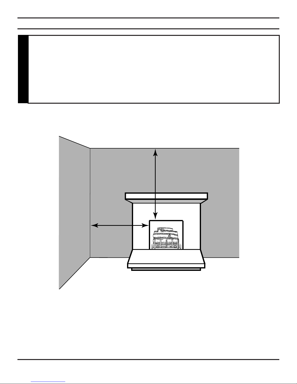
W
H
The following formula can be used to determine the maximum heater rating per the definition of unconfined space:
BTU/Hr = (L1 + L2) Ft x (W) Ft x (H) Ft
50
Consider two connecting rooms with an open area between, with the following dimensions:
L1 = 151/2 Ft., L2 = 12 Ft., W = 12 Ft., H = 8 Ft.
BTU/Hr = (151/2 + 12) x (12) x (8)
50
If there were a door between the two rooms the calculation would be based only on the room with the heater.
BTU/Hr = (151/2) x (12) x (8)
50
GENERAL INSTALLATION INFORMATION
Figure 1 - Example of a Large Room with 1/2 Wall Divider
Counter
Fireplace
x 1000
x 1000 = 52800 BTU/Hr
x 1000 = 29760 BTU/Hr
If the area in which the heater may be operated is smaller than that defined as an
unconfined space or if the building is of unusually tight construction, provide adequate
combustion and ventilation air by one of the methods described in the National Fuel
Gas Code, ANSI Z223.1, Section 5.3 or applicable local codes.
WARNING

65D0001 9
C
A
D
B
WARNING
FIREPLACE AND HEARTH DIMENSIONS
Use manufacturer's installation and clearance requirements as defined in their manual.
The DYD Series unvented room heater is approved for installation into the following unvented fireplaces:
GCUF(32,36,42) and VFR(32,36,42) Series Fireboxes
The DYD Series unvented room heater may also be installed into a Ventless Firebox Enclosure for Gas Fired Decorative
Type Unvented Room Heaters per ANSI Z21.91b.2004, as long as firebox hearth dimensions meet the minimum hearth
dimensions shown below.
Figure 2 - Hearth Minimum Dimension for Solid Fuel Burning
Fireplaces and UL127 Factory Built Fireplaces
This appliance has been specifically tested and design certified for installation only
in a solid-fuel burning fireplace including factory-built UL127 fireplaces and masonry
fireplaces, or in a listed ventless firebox (see below).
Exception: DO NOT install this appliance in a factory-built fireplace that includes
instructions stating that it has not been tested or should not be used with unvented
gas logs.
WARNING
Model A B C D
DYD 29" 131/4" 171/2" 17"

10 65D0001
LO
HI OFF
ON
I
G
N
PLACEMENT IN A FIREPLACE WITH A RESTRICTIVE BARRIER
IMPORTANT INFORMATION FOR THE INSTALLATION OF THIS GAS LOG SET
The following are guidelines for placing a gas log set in a fireplace that has a restrictive barrier along the bottom front open-
ing of the fireplace. Some examples of barriers are glass/screen door frames and sunken/recessed fireplaces.
Glass door frames
with adjustable
louvers should have
the lovers fully open
while the unit is in
operation.
Height of restrictive barrier
caused by glass door frames,
recessed fireplaces, etc. from
the base or bottom surface of the
unit. (See Table).
The log set should be
placed against or as near
as possible to the rear wall
of the fireplace/firebox.
Depth of fireplace/firebox.
(SeeTable).
Figure 3 - Reference Drawing of a Natural Flame Log Set in an Enclosure
NOTE: Non combustible material such as refractory brick may be used to line the floor of the fireplace
in order to raise the height of the gas log set in relation to a restrictive barrier. If the unit is raised, the
minimum height dimension listed in the homeowner’s manual must not be exceeded.
NOTE: If the log set is equipped with a remote receiver, a restrictive barrier may reduce the battery life
by increasing the ambient temperature inside the fireplace. Placement of the receiver outside of the
fireplace will extend the battery life.
X
Barriers such as the bottom of a glass door frame placed in front of a gas log set can
change the air flow characteristics of the fireplace which in turn can cause the unit to
overheat and malfunction.
WARNING
Height of Restriction (X) Minimum Depth of Fireplace/Firebox
No restriction 13"
0 to 1.5" 16"
Greater than 11/2" to 3" 16"
Greater than 3" Any barrier greater than three inches (3") placed in front of the gas log set is not
recommended by the manufacturer.
65D0001 11
16"
42"
CLEARANCES AND HEIGHT REQUIREMENTS
Sidewall and ceiling clearances: The sides of the fireplace opening must be at least 16" from any combustible wall.
The ceiling must be at least 42" from the top of the fireplace opening.
Figure 4 - Sidewall and Ceiling Clearances
The dimensions shown in Figures 4 through 10 and defined in the fireplace manufacturer's
instructions are minimum clearances to maintain when installing this heater. Left and
right clearances are determined when facing the front of the heater.
When heater is installed into a ventless firebox, minimum clearances, as specified by
the ventless firebox manufacturer, must be met.
Follow these instructions carefully to ensure safe installation. Failure to follow
instructions exactly can create a fire hazard.
WARNING
12 65D0001
Heater in
Fireplace or
Firebox
8" or More of
Heat Resistant
Material
Hood
Measure
this
distance
Heater in
Fireplace or
Firebox
Heat
Resistant
Material
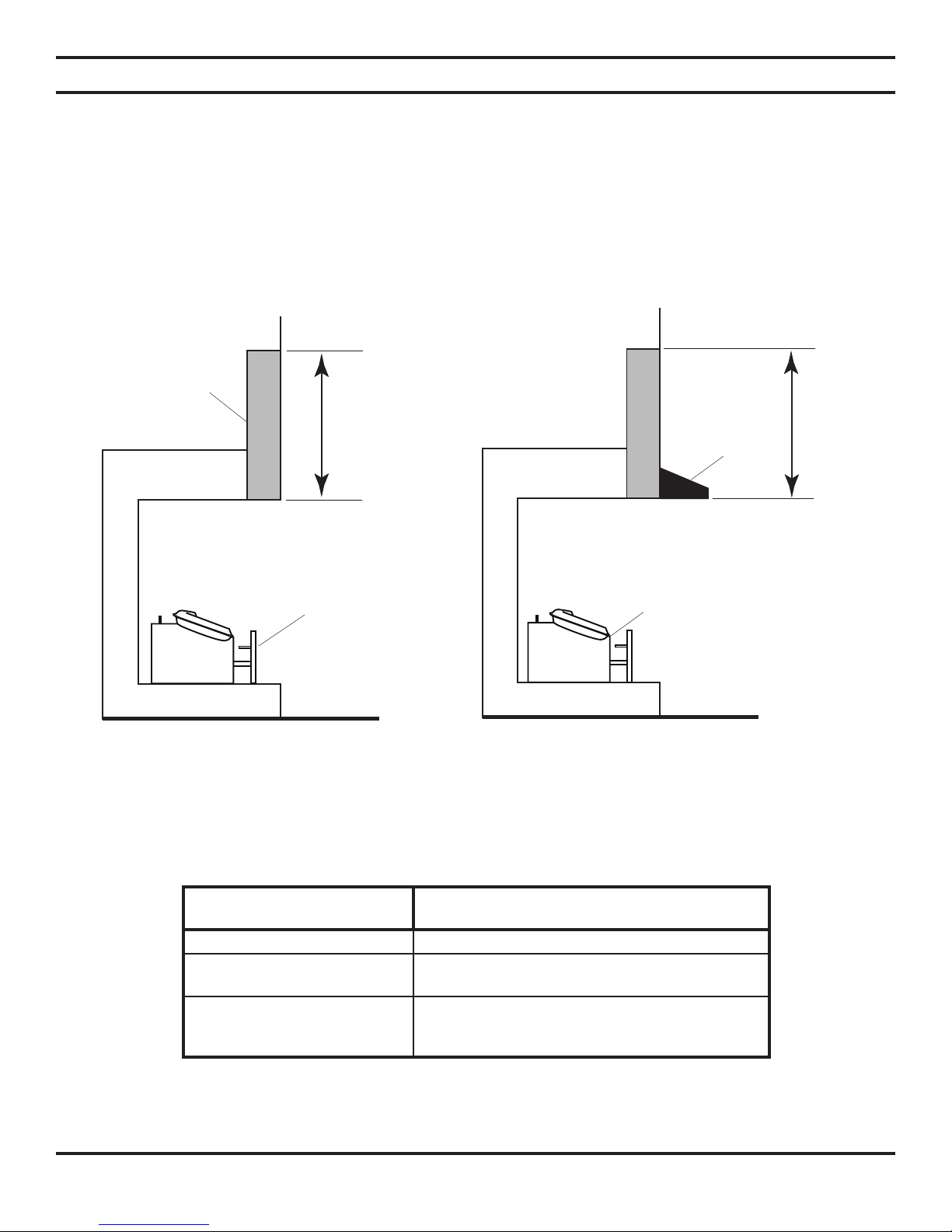
Heat resistant material (minimum requirements) with wooden mantel or other combustible projection:
To install the heater with a wooden mantel, shelf or other combustible projection above, first measure the heat resistant
material shown in Figure 6.
Figure 6 - Measuring Heat Resistant Material
for Mantel
CLEARANCES and HEIGHT REQUIREMENTS
Heat resistant material (minimum requirements) with no wooden mantel or other combustible projec-
tion:
To install the gas logs into a fireplace with no wooden mantel, shelf or other combustible projection above the fireplace
opening, measure the heat resistant material height, per Figure 5, then see TABLE A.
Heat resistant materials such as slate and marble must be at least 1/2" thick. Sheet metal should not be installed onto
combustible material.
IMPORTANT: If you cannot meet these minimum clearances you must operate the heater with chimney flue damper open.
See Installing Vented Applications found on page 16.
Figure 5 - Measuring Heat Resistant Material
TABLE A - Heat Resistant Material Requirements with No Mantel or Combustible Projection
HEAT RESISTANT MATERIAL
MEASUREMENT
DYD24/18
REQUIREMENTS FOR SAFE INSTALLATION
20" or more Hood not required.
8" to less than 20" Extend heat resistent material to 20" or install Hood.
See Figure 6.
Less than 8" Extend heat resistant material to at least 8" and
install hood. See Figure 6. OR, extend heat resistant
material to a height of at least 20".

65D0001 13
Heater in Fireplace or Firebox
Heat
Resistant
Material
Hood
12"
6" - 10 "
21/2"
8"min. 13" 18" 20"
Heater in
Fireplace or
Firebox
Heat
Resistant
Material
10" or less
20" min. 32"
CLEARANCES AND HEIGHT REQUIRMENTS
TABLE B - Heat Resistant Material Heights and Mantel Location
Figure 8 - Minimum Mantel Clearance
with No Hood
Figure 7 - Minimum Mantel Clearance
with Hood
Example: The bottom of the mantel may project from the
wall a maximum of 10" at a minimum of 32"
above the opening.
Example: A mantel may project from the wall a maxi-
mum of 2 1/2" at a minimum of 13" above the
opening and a maximum of 10" at a minimum
of 18" above the opening.
HEAT RESISTANT MATERIAL
MEASUREMENT
REQUIREMENTS FOR SAFE INSTALLATION WITH WOODEN MANTEL, SHELF
OR OTHER COMBUSTIBLE PROJECTION
20" or more Hood not required. Observe profiles (side elevations) shown in Figure 8.
8" to less than 20" Install hood (CABR/CABL) and observe profiles shown in Figure 7; OR extend heat
resistant material to at least 12" and observe profiles shown in Figure 8.
Less than 8" Extend heat resistant material to at least 8", install hood (CABR/CABL) and observe
profiles shown in Figure 7; OR extend heat resistant material to at least 12" and observe
profiles shown in Figure 8.

14 65D0001
Heater in
Fireplace or
Firebox
5" Minimum
Combustible
Material
14" Minimum
Heater in
Fireplace or
Firebox
Combustible
Material
This Distance
May Now Be
Less than 5"
FLOOR CLEARANCE
The gas log heater must be installed at least 5" above any combustible flooring material, such as carpeting or tile, which is
closer than 14" to the base of the fireplace. The minimum distance must be maintained from the top surface of carpeting,
tile, etc. See Figure 9.
OR,
The gas log heater may be installed nearer to the floor if a minimum of 14" of noncombustible material such as slate or marble
is installed between the base of the fireplace and the combustible flooring. See Figure 10.
Figure 9 - Minimum Clearance above Combustible Flooring
Figure 10 - Minimum Clearance above Combustible Flooring with
Noncombustible Material Installed at Base of Fireplace
65D0001 15
Damper Stop
Damper
Figure 11 - Damper Stop Installation.
(See WARNING at top of next page.)
FIREPLACE PREPARATION
BEFORE FULLY INSTALLING THE UNIT:
• Turn OFF the gas supply to the fireplace or firebox.
• Seal any fresh air vents and/or ash clean-out doors located on the floor or wall of the fireplace. If left unsealed, drafting
may cause pilot outage or sooting. Use a heat resistant sealant. Do not seal the chimney flue damper.
INSTALLING VENTED APPLICATIONS
Manual and millivolt controlled gas logs may be installed as a vented decorative log set in compliance with ANSI Z21.60
and National Fuel Gas Code, Section 6.6 Since, the gas logs are operated with the damper open, non-combustible material
and minimum mantel requirements do not apply.
BEFORE INSTALLING THE APPLIANCE:
• Turn off gas supply to fireplace or firebox.
• Have the fireplace floor and chimney professionally cleaned to remove ashes, soot, creosote or other obstructions. Have
this cleaning performed annually after installation.
• Seal any fresh air vents or ash clean-out doors located on floor or wall of fireplace. If not, drafting may cause pilot out-
age or sooting. Use a heat-resistant sealant. Do not seal chimney flue damper.
Install and operate the appliance as directed in this
manual.
DAMPER STOP INSTALLATION:
A damper stop must be provided with the unit. Contact
your dealer to obtain one. The damper stop must be
installed as shown in Figure 11 to prevent full closure
of the fireplace damper blade and provide a minimum
29 square inch flue opening.
Before installing in a solid fuel burning
fireplace, The chimney flue and firebox
must be cleaned of soot, creosote,
ashes and loose paint by a qualified
chimney cleaner.
WARNING
This appliance is for installation only in a solid fuel burning fireplace (masonry fireplace
or manufactured fireplace) with a working flue and constructed of noncombustible
material.
Exception: DO NOT install this appliance in a factory-built fireplace that includes
instructions stating that it has not been tested or should not be used with unvented
gas logs.
WARNING

16 65D0001
LO
HI OFF
ON
I
G
N
INSTALLING VENTED APPLICATION
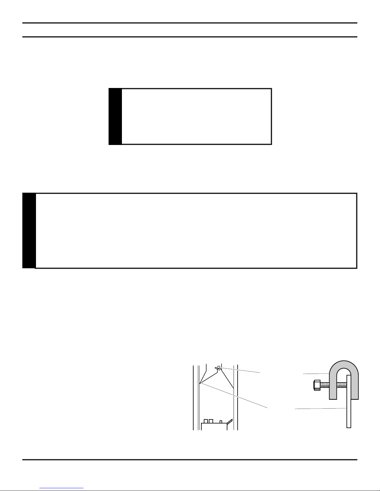
PLACING AND SECURING APPLIANCE
ASSEMBLY PROCEDURE:
1. Center the gas log unit in the fireplace or firebox. Make certain the front feet of the grate sit inside the front edge of the
fireplace or firebox.
2. Anchor holes are located on the flange of the unit. See Figure 12. After centering the grate correctly, mark the hole
positions on the fireplace/firebox floor. Drill two (2) 5/32" diameter holes approximately 11/2" deep.
3. Anchor the grate to the fireplace/firebox floor using the screws provided. See Figure 12.
Proper installation of the grate is essential to prevent any movement of the gas logs and controls during operation.
Figure 12 - Securing Heater to Floor of Fireplace/Firebox
The fireplace and gas logs function as a system. If the fireplace is spilling into the room
(check with a match or a smoke stick), reposition the damper clamp until a positive
draft is obtained by opening the damper. If negative pressure in home prevents having
a positive draft, contact your dealer for assistance.
WARNING
You must secure the gas log heater to the fireplace floor. If not, the entire unit may move
when you adjust the controls. Movement of unit may cause shifting of the gas logs which
leads to sooting and improper burning. Grate movement could cause a gas leak.
Special care is required if you are installing the unit into a sunken fireplace. You must
raise the fireplace floor to allow access to gas log controls. This will insure adequate air
flow and guard against sooting. Raise the fireplace floor using noncombustible materials,
as described in Placement in a Fireplace with Restrictive Barrier on page 10.
WARNING
Anchor
Hole
Screw
Screw

65D0001 17
Pipe Coupling
To Heater
Valve
Gas Supply
Inlet
CONNECTING THE GAS
NOTICE: A qualified gas appliance installer must connect the heater to the gas supply. Consult all local
codes.
IMPORTANT: Hold heater valve firmly with a wrench to prevent movement when connecting to inlet pipe.
Manual Shutoff
Valve
Pipe
Stainless
Flexible Tube
Figure 13 - Gas Connection
Always use an external regulator for all propane/LPG heaters and high pressure one to two-pound systems only, to
reduce the supply tank pressure to a maximum of 13" w.c. This is in addition to the internal regulator in the heater valve.
Locations that the Pressure
Tapping Point May Be Installed
Use new black iron or steel pipe. Internally tinned copper or copper tubing can be used
per National Fuel Code, section 2.6.3, providing gas meets hydrogen sulfide limits, and
where permitted by local codes. Gas piping system must be sized to provide minimum
inlet pressure (Listed on Data Plate) at the maximum flow rate (BTU/Hr). Undue pressure
loss will occur if the pipe is too small.
A manual shutoff valve must be installed upstream of the appliance. Union tee and
plugged 1/8" NPT pressure tapping point should be installed upstream of the appliance.
See Figure 13.
CAUTION
CHECK GAS TYPE: The gas supply must be the same as stated on the heater’s rating
plate. If the gas supply is different, DO NOT INSTALL THE HEATER. Contact your dealer
for the correct model.
CAUTION

18 65D0001
Test Port “OUT”
WARNING
CHECKING GAS PRESSURE
The heater gas inlet connection is a 3/8" NPT at the valve. On units
with Millivolt control, the inlet connection is on the right side, when
you face the unit. On units with manual control, the inlet connection
is on the right. To connect from the opposite side, route the pipe
under the rear portion of the unit.
When tightening up the joint to the valve, hold the valve securely
to prevent movement.
NPT Test Plug
MANUAL CONTROL (Figure 14)
The pressure regulator is preset and locked to dis-
courage tampering. If the pressure is not as specified,
replace the regulator with the correct part from the parts
list in this manual.
Remove 1/8" NPT plug, located on side of regulator
body. Install fitting and tubing to pressure gauge. After
taking pressure reading, reinstall test plug. Check for
gas leaks.
MILLIVOLT CONTROL (Figure 15)
The valve regulator controls the burner pressure which
should be checked at the pressure test point.
Turn captured screw counter clockwise two or thre
turns and then place tubing to pressure gauge over test
point (Use test point “OUT” closest to control knob).
After taking pressure reading, be sure and turn captured
screw clockwise firmly to re-seal. Do not over torque.
Check for gas leaks.
Figure 14 - Pressure Test Point Location
Manual Control
Figure 15 - Pressure Test Point Location
Millivolt Control
Test all gas joints from the gas meter to the heater valve for leaks using a gas analyzer or soap and water solution after com-
pleting connection. DO NOT USE AN OPEN FLAME.
Check the gas pressure with the appliance burning and the control set to HIGH.
Connecting directly to an
unregulated propane/LPG tank
can cause an explosion.
WARNING
65D0001 19
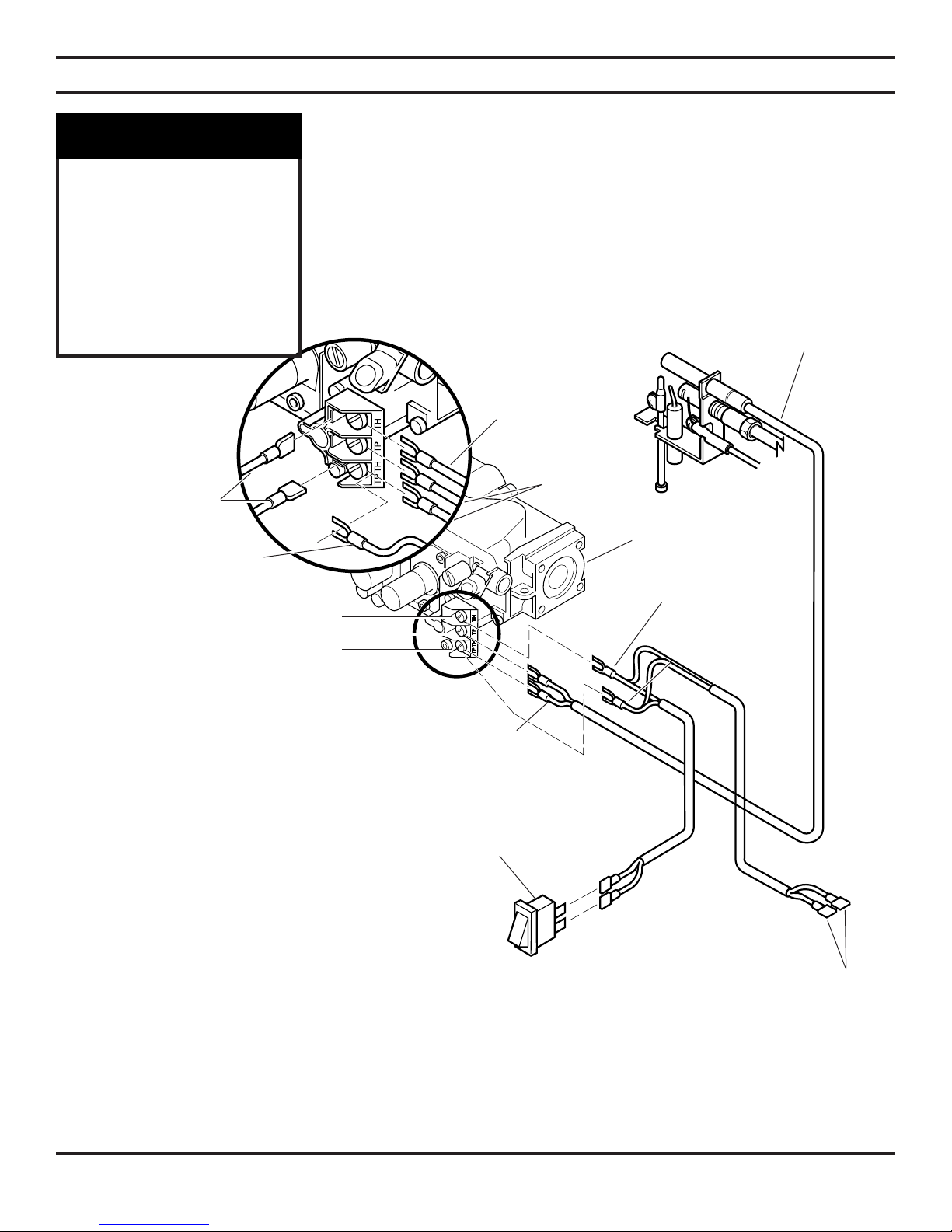
ELECTRICAL WIRING (MILLIVOLT)
The millivolt valve is a self-powered combination gas control THAT DOES NOT
REQUIRE 110 VAC TO OPERATE.
CONNECTING OPTIONAL WALL SWITCH OR THERMOSTAT
1. Use 18 awg, two-wire cable, 20 feet maximum length.
2. At one end of the cable, connect both wires to the wall switch or thermostat. At the other end, connect one wire to TP/TH
and one wire to TH. The color of the wires does not matter. Or you can hook the wall switch of thermostat to wires on
the left side of the unit.
Figure 16 - Wiring Diagram
Optional Wall
Switch or Remote
Receiver
Switch
On/Off
Switch
On/Off
Switch
Wall
Switch
ODS
Pilot
Millivolt
Valve
Red
TH = 3
TP = 1
TP/TH = 2 Red
ODS
Pilot
Spade
Terminal
Label all wires prior to
disconnection when
servicing controls.
Wi rin g err or s can
cause improper and
dangerous operation.
Verify proper operation
after servicing.
CAUTION
20 65D0001
LO
HI OFF
ON
I
G
N
SKYTECH
OFF ON
REMOTE
ELECTRICAL WIRING (MILLIVOLT)
A. COMPLETE MILLIVOLT SYSTEM CHECK
(“A” Reading - Thermostat contacts CLOSED - Control Knob “ON” - Main burner should come ON)
a. If the reading is more than 100 millivolts and the automatic valve still does not come on, replace the control.
b. If the closed circuit reading (“A” reading) is less than 100 millivolts, determine cause for low reading, proceed to
Section B below.
B. Thermopile Output Reading Check
(“B” Reading - Thermostat contacts OPEN - Main burner OFF)
1. Check gas pressure to the unit. If gas pressure is within minimum and maximum on data plate, then check pilot
voltage, 325 millivolts minimum. If the minimum millivolt reading is not obtainable, replace pilot.
CHECKING SYSTEM OPERATION
The millivolt system and individual
components may be checked with
a millivolt meter having a 0-1000
mV range. Conduct each check
shown in chart below by connect-
ing meter test leads to terminals as
indicated.
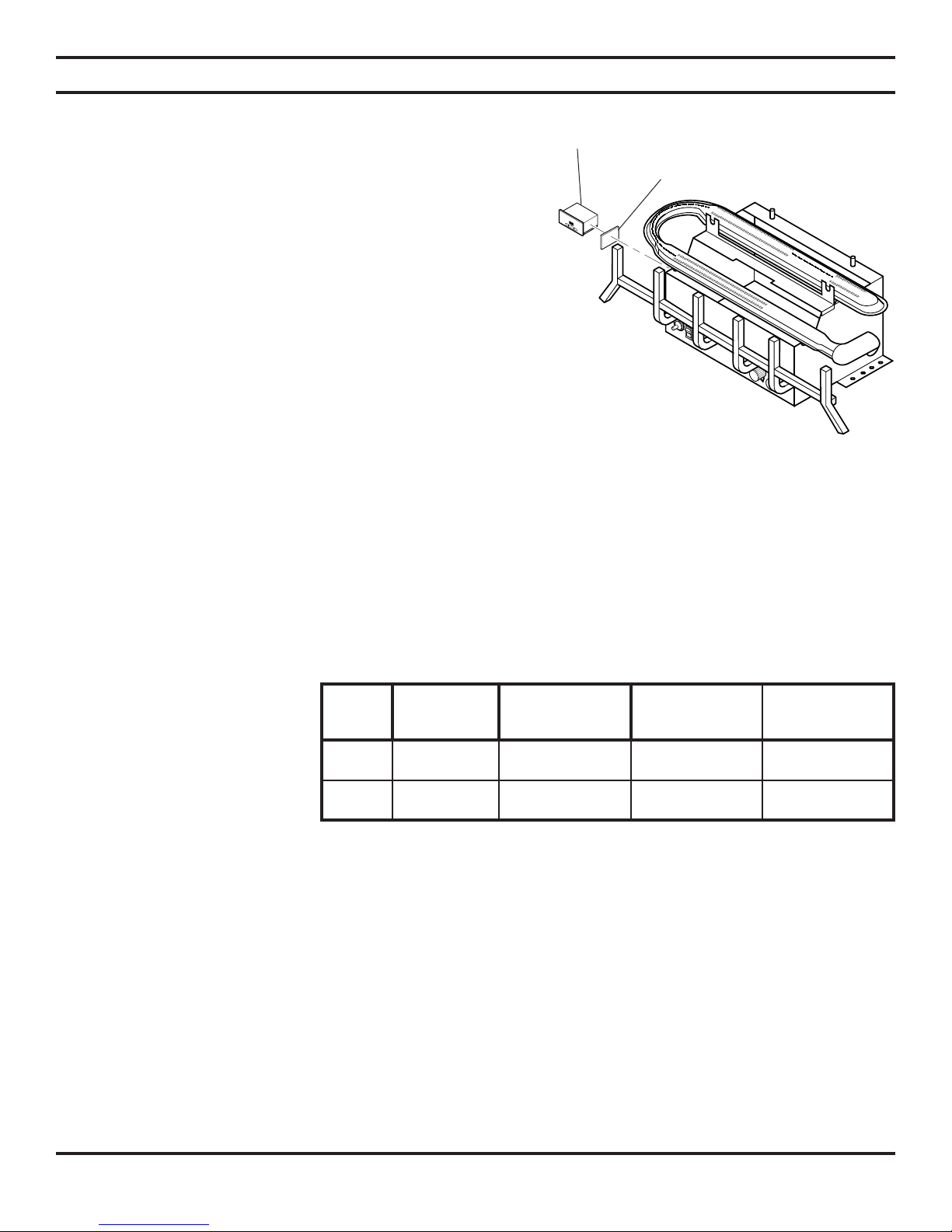
Figure 17 - Installing Remote Receiver
Velcro Pads
Remote
Receiver
CHECK
TEST TO TEST
CONNECT
METER LEADS
TO TERMINALS
THERMOSTAT
CONTACTS
METER READING
SHOULD BE
ACOMPLETE
SYSTEM 2 & 3 CLOSED CLOSED
BTHERMOPILE
OUTPUT 1 & 2 OPEN OPEN
CONNECTING REMOTE RECEIVER
THESE INSTRUCTIONS SUPERCEDE THE SECTION EN-
TITLED “HEARTH MOUNT” IN THE MILLIVOLT HAND-HELD
REMOTE INSTRUCTIONS SUPPLIED WITH THE REMOTE.
1. Cut cable to length (approximately 12") for placement in the fire-
place.
2. Strip back 1/4" of the insulation from both ends of each wire.
3. Connect two .25 female connectors to the wires at one end of the
cable.
4. Insert the opposite ends of the wires into the receiver wire terminals
and tighten the screws.
5. Connect the connectors to the two .25" male connectors located
on the left side when facing the unit (See Figure 16, page 19). Do
not let wire touch grate or burner.
6. Stick velcro pads with self-adhesive backing to bottom of remote
receiver and to the left side of the unit. See Figure 17.
7. Attach remote receiver with velcro pads. Control switch must face
forward.
NOTE: Heat reduces battery life. You can protect the
receiver and extend battery life by mounting the receiver in
a wall or other location outside the fireplace.
This manual suits for next models
2
Table of contents
Other MHS Boilers Heater manuals


Popular Heater manuals by other brands

Empire Products
Empire Products RH-25-6 Installation instructions and owner's manual

Conrad
Conrad Cube operating instructions

Sonnenkonig
Sonnenkonig MERSIN user manual

DeLonghi
DeLonghi Electric radiator instructions

DR. Heater
DR. Heater DR-999 owner's manual

simatherm
simatherm IH 045 Quick installation guide


Berner
Berner AI08 Installation & maintenance instructions
 Translation of the original instruction manual")
Heylo
Heylo K 120 (R) Translation of the original instruction manual

Lasko
Lasko 5538 operating manual

L.B. White
L.B. White Workman CV225 Owner's manual and instructions

Pentair
Pentair ETi 400 Installation and user guide

Dimplex
Dimplex SmartRad SRX80 Planning guide