MHZ nova-02 User manual

Installation instructions
Edition 10.2020
nova_02 tube awning

2
Page
Subject to technical changes, Edition 10.2020
Table of contents
Safety Instructions for the Installation 3 to 7
Installation Instructions 9 to 17
Adjustment instructions for Sun Top drives 19
Adjustment instructions for OREA RTS radio-controlled drives 20
Adjustment instructions for Sunea io radio-controlled drives 21
nova_02 tube awning installation instructions

3
Subject to technical changes - Edition 10.2020
1. Reading the installation and operating instructions
The operating instructions must be read prior to
installation. Any failure to do so absolves the manufacturer
of any duty of liability
1.1. Safety notes and warnings relating to installation
instructions
Safety notes can be found throughout the text. They are
marked with a symbol and a note:
Important safety information:
Notes that are important for the functioning of the product
and can result in serious injury or death in the event of
improper use are marked with this warning triangle.
Important safety information:
This warning triangle indicates notes that are important
for the functioning of the product and that if not followed
represent a risk of electrocution that can result in serious
injury or death.
1.2. Qualification
These installation instructions are aimed exclusively at quali-
fied fitters with sound knowledge in the following areas:
Health and safety at work and accident
prevention regulations
Handling of ladders and scaffolding
Handling and transport of long, heavy
components
Working with tools and machines
Attaching fasteners Assessing the fabric of
buildings Commissioning and operating
the product
In the absence of any of these qualifications, a
specialist fitting company must be employed to install
the product.
Electrical work:
The permanent electrical installation must be carried
out by a qualified electrician in accordance with the national
regulations. Installation instructions are enclosed with the
electrical appliances supplied with the awning. These must
be followed.
1.3. Goods acceptance
The delivery must be inspected immediately upon receipt for
any damage sustained in transit. In addition, the contents of
the shipment must be checked against the delivery note.
1.4. Transport
The permitted axle load and permitted total weight of
the transport vehicle may not be exceeded. Loading can
effect the vehicle's handling.
The goods being transported are to be tied down and
properly secured. The shade system packaging is to be
protected against moisture. Any soaked packaging may
disintegrate and result in accidents. Packaging opened for
the purpose of goods receipt inspection must be properly
taped up for further transportation.
After the awning is unloaded, it is to be transported to the
installation site the right way up and in the proper installation
position so that it does not have to be manoeuvred through
tight spaces.
The note on the position and side information on the awning
box is to be adhered to.
1.5. Pulling up with ropes
If the awning system needs to be pulled up to a higher
position with the help of ropes, the awning is to be
taken out of the packaging,
fastened to the hoisting ropes in such a wa
that they cannot slip off, and
pulled up smoothly in a vertical position.
The same applies to taking down the awning.
1.6. Mounting brackets
Before starting installation, check
that the type and number of fitting brackets supplied
match the order
that the details given with the order about the
substructure to which the awning is to be fixed match
the actual substructure found at the installation site.
If any variances that impair safety are identified, the installation
may not be carried out.
Important safety instructions for the installation
nova_02 tube awning installation instructions
!
!
!
!
!
!
4
NB:
Supplied without installation materials (available as accesso
ries). Installation materials need to be matched by the fitter to
the given installation substructure.
Where fastening materials ordered with the system are used
we do not simultaneously assume liability for proficient
installation. The installer is exclusively liable for determining if
the fastening materials for the respective masonry are suitable
and for the installation being performed properly. The wall
plug manufacturers' respective fitting guides must be followe
1.7. Fasteners
The awning fulfils the requirements of the wind resistance
category specified in the CE conformity mark (see operating
instructions). In installed condition, this requirement is only
met if:
the awning is installed using the type and number
of brackets recommended by the manufacturer
(see point 1.17 on page 6+7)
the awning is installed taking account of the wall
plug extraction forces specified by the manufacturer
(see point 1.17 on page 6+7)
that during installation attention has been paid to the
guidance of the manufacturer of the wall plugs used.
1.8. Climbing aids
Climbing aids may not be attached to or leant against
the awning. They must be steady and provide adequate grip.
Only use ladders that are certified for the proper load
bearing weight.
1.9. Fall protection equipment
There is a risk of falling when working at any significant
height. The appropriate fall protection equipment is to be
used to guard against falls
1.10. Electrical connection
The awning may only be connected if the electric motor's
specifications match the electricity source (see operating
instructions). The electrical component installation notes
supplied with the unit must be followed.
The unit is to be protected with an upstream FI circuit
breaker in accordance with VDE regulations.
Only cables and connectors with a protection class of a
minimum of IP 54 may be used to supply power.
1.11. Partially assembled awnings
Where awnings are partially assembled at the factory,
e.g. linked systems with no fabric, the spring-loaded parts
(see marking on the product) are secured against inadvertent
opening. The securing device must not be removed until the
blind has been completely installed.
These marked, spring-loaded blind components present
a high risk of injury!
1.12. Intended use
Awnings may be used only for the purpose defined for
them in the operating instructions. Changes, such as attach
ments and modifications not intended by the manufacturer
may only be carried out with the manufacturer's written
consent.
Additional loading of the awnings by attaching objects or by
cable tensioning or the like can result in damage to the
awning or to it falling down; this is not permitted.
Important safety instructions for the installation
nova_02 tube awning installation instructions
Subject to technical changes - Edition 10.2020
!
!
!
!
!
!
!
!
1
2
3
4
MHZ Hachtel GmbH & Co. KG
Sindelfinger Straße 21
D-70771 Leinfelden-Echterdingen
Germany
2018
LE-001
EN 13561:2015
art_01, art_02, VEGAS, nova_02
CLASSIC, CLASSIC MAXIMA
Use on the outside of buildings
and other structures
Resistance to wind loads: Class 1
Total energy transmittance g : NPD
tot
*
* For awnings mounted on wooden substructures and/or to
rafters, and for awnings in special sizes or finishes, it is not
possible to state wind resistance classes (class 0).
Example of a CE Conformity Mark in the accompanying document:
1
2
3
4
CE conformity mark, consisting of the
CE mark defined in Directive 93/68/EEC.
Name or identification code and the registered
address of the manufacturer.
The year that the CE mark was issued.
Declaration of performance reference number.
Number of the European standard applied,
as given in the EU's Official Journal.
Product type's unique identifying code.
Product's intended purpose, as
specified in the European norm.
Level and class of the stated power output.
5
Subject to technical changes - Edition 10.2020
1.13. Unsupervised operation
When working in the extension area of the awning, the
automatic controller must be turned off. There is a risk of
crushing or falling.
In addition, ensure that the system cannot be unintentionally
manually operated. For this purpose, the power is to be cut,
e.g. take out the fuse or disconnect the plug. Furthermore, in
the case of manual operating systems the operating crank
must be removed and securely stored.
If the awning is used by several users, a priority locking
system (controlled external electricity turn-off switch) must
be used, which makes the retraction and extension of the
awning impossible during cleaning and maintenance work.
1.14. Trial run
The first time the system is extended, no one is permit-
ted in the extension area of or under the awning.
A visual check must be made of the fasteners and brackets
after the first trial run.
During trial runs the automatic control or switch may not be
used if the awning is out of the operator's sight (there is a risk
of unintended extension/retraction). The use of a test cable
to turn on the motor is recommended.
The installation and adjustment instructions included with
the awning from the manufacturers of the motor, switch and
controller must be followed.
1.15. Crush and shear zones
There are crush and shear zones between drop bar
and tube/cassette and/or covers near the joint arm and
moving sections. Clothing i.e. body parts can be pulled
into the system!
If the awning is being installed at a height of less than
2.5 metres above accessible thoroughfares, it may be turned
on only by a push button switch from which there is a view of
the moving parts. Electrical controllers, radio drives with
latching function, latching switches, etc. are not permissible
in this case.
The push-button switch must be fitted within sight of the
drop bar but away from the moving parts. Ideally it should
be fitted at a height of 1.3 metres (national regulations
relating to the disabled must be observed).
1.16. Handover
All operating instructions as well as the installation
and adjustment instructions issued by the motor, switch and
controller manufacturers are to be handed over to the user
with an induction session. The user is to be instructed
comprehensively on safety and on use of the awning.
Failure to follow the instructions or any incorrect operation
can cause accidents and damage to the awning.
All instructions are to be kept by the customer for future
reference and must be passed on to the new owner if the
awning is sold.
Based on knowledge of the particular circumstances at the
site and the finished installation, the installation firm will
tell the user whether the wind resistance class specified by
the manufacturer has been achieved in the installed conditi
on. If not, the installation company must document the wind
resistance class actually attained.
Recommendation:
If you are the fitter, have the awning’s correct installation
and set-up, the time of installation and details of the accep
tance meeting, including that you explained the safety
information, confirmed in writing.
Important safety instructions for the installation
nova_02 tube awning installation instructions
!
!
!
!

HF 8
WK6
HI
WK8
KS
HK
KU
12
WK10
WK11
DK3
14
8
HH 12
4xø15
20
150
203 mm
175 mm
20
4xø15
22,2
4xø17
22,2
20
150
230 mm
25 150
200 mm
340 mm
20 300
50 280
350 mm
12
6xø17
203 mm
175 mm
175
20 135
135
20
203 mm
175 mm
140
22,5 95
135
20
135
KF
KH
8
12
130 mm
65
50 280
350 mm
12
2xø17
KT
KV
12
DK7
!
1
1
1
Subject to technical changes - Edition 10.2020
6
Important safety instructions for the installation
nova_02 tube awning installation instructions
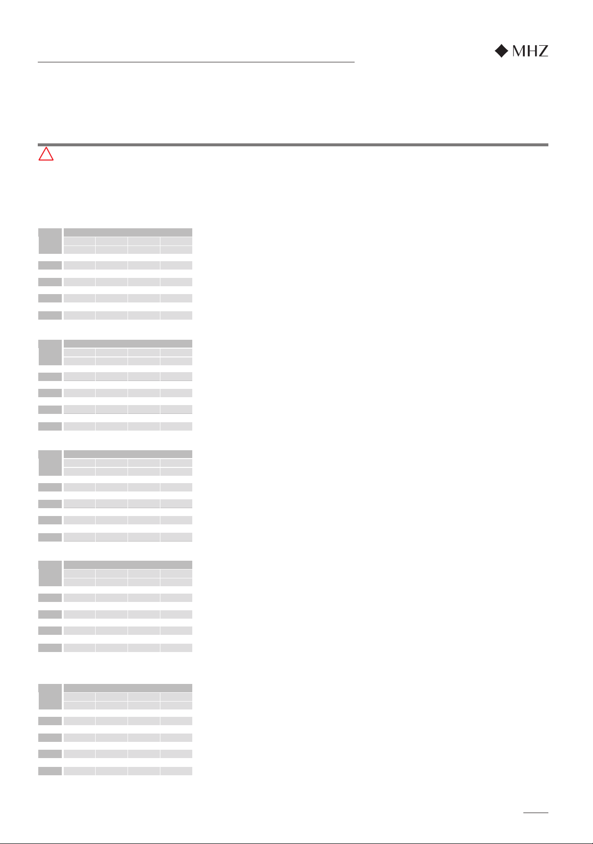
B-set = bracket set; WK = wall bracket; DK = ceiling bracket
*1 Galvanised, powder-coated in frame colour
*2 Bracket set in combination with roof rafter bracket
Note: Brackets must be installed on the arm bracket.
Pay attention to the centre-to-centre distance.
1.17. Bracket arrangement and extraction forces
Be sure to take note of all key installation information!
All brackets supplied with the product must be used and they must be fitted using all fixing points.
Pay attention to the extraction forces (see p. 7).
Standard wall bracket set
consisting of 2-off WK6
B-set Description Bracket arrangement Illustration
Fixing
points
Wall bracket set
consisting of 2-off WK8
for installation on difficult substructures
Wall bracket set
consisting of 2-off WK10
(1 each of WK6 and steel plate *)
for fixing to critical substructures
Ceiling bracket set
consisting of 2-off DK3
Standard wall bracket set
consisting of 3-off WK6
Wall bracket set
consisting of 3-off WK8
for installation on difficult substructures
Wall bracket set
consisting of 2-off WK10
(1 each of WK6 and steel plate *)
and 1-off WK11 (1 each of WK6 and steel
plate *) for fixing to critical substructures
Roof rafter bracket set *
consisting of 2-off DK7
2
Ceiling bracket set
consisting of 3-off DK3
Roof rafter bracket set *
consisting of 3-off DK7
2
7
250 359 HF 556 HF
300 413 HF 639 HF 911 HF
350 467 HF 723 HF 1.029 HF 1.391 HF
400 521 HF 806 HF 1.148 HF 1.550 HF
450 575 HF 890 HF 1.267 HF 1.710 HF
500 629 HH 973 HH 1.385 HH 1.869 HH
550 683 HH 1.057 HH 1.504 HH 2.272 HH
600 737 HH 1.140 HH 1.622 HH 2.454 HH
250 491 KS 727 KS
300 568 KS 839 KS 1.164 KS
350 646 KS 952 KS 1.318 KS 1.751 KS
400 723 KS 1.064 KS 1.473 KS 1.954 KS
450 800 KS 1.176 KS 1.627 KS 2.157 KS
500 877 KT 1.289 KT 1.781 KT 2.360 KT
550 954 KT 1.401 KT 1.936 KT 2.854 KT
600 1.031 KT 1.514 KT 2.090 KT 3.085 KT
250 307 KF 476 KF
300 354 KF 548 KF 782 KF
350 401 KF 621 KF 884 KF 1.196 KF
400 447 KF 693 KF 987 KF 554 HI
450 494 KF 765 KF 1.090 KF 611 HI
500 541 KH 838 KH 1.193 KH 669 HK
550 588 KH 910 KH 535 HK 813 HK
600 635 KH 983 KH 581 HK 879 HK
150 200 250 300
250 307 KF 476 KF
300 354 KF 548 KF 782 KF
350 401 KF 621 KF 884 KF 1.196 KF
400 447 KF 693 KF 987 KF 554 HI
450 494 KF 765 KF 1.090 KF 611 HI
500 541 KH 838 KH 1.193 KH 669 HK
550 588 KH 910 KH 539 HK 813 HK
600 635 KH 983 KH 581 HK 879 HK
150 200 250 300
250 307 KF 476 KF
300 354 KF 548 KF 782 KF
350 401 KF 621 KF 884 KF 497 HI
400 447 KF 693 KF 987 KF 554 HI
450 494 KF 765 KF 453 HI 611 HI
500 541 KH 838 KH 496 HK 669 HK
550 588 KH 910 KH 539 HK 813 HK
600 635 KH 983 KH 581 HK 879 HK
150 200 250 300
!
WALL installation on brick MZ 12
Projection in cm
Width
in cm
N B-Set N B-Set N B-Set N B-Set
WALL installation on hollow brick HLZ 12
Projection in cm
Width
in cm
N B-Set N B-Set N B-Set N B-Set
WALL installation on cellular concrete PB2
Projection in cm
Width
in cm
N B-Set N B-Set N B-Set N B-Set
Subject to technical changes - Edition 10.2020
WALL installation on concrete (C20/25)
Projection in cm
Width
in cm
N B-Set N B-Set N B-Set N B-Set
150 200 250 300
CEILING installation on concrete (C20/25)
Projection in cm
Width
in cm
N B-Set N B-Set N B-Set N B-Set
150 200 250 300
N = extraction force in Newtons (N) per fastening screw; K set = specified bracket set (see overview on page 6)
Important safety instructions for the installation
nova_02 tube awning installation instructions
So that the wind resistance class specified by us is valid, the fasteners must be matched to the existing substructure by the fitter.
Where orders are received without specification of the installation substructure, you will receive mounting brackets for mounting on concrete C 20/25. Please note that these
brackets may not be suitable for installation on other substructures. In order to satisfy DIN EN 13561, it is necessary to fit the type and number of brackets recommended for each
product. It is essential to observe the defined wall plug extraction forces as well as the mounting and installation instructions given by the manufacturer of the fasteners (including
the edge and hole distances). Precise extraction forces in relation to the thickness of the insulating plaster and the desired bracket set as well as to installation on other substructures
on request.
Coupled systems are counted as two individual systems (system width = 1/2 total width). The bracket set (K set) is required twice.
EXTRACTION FORCES AND BRACKET SETS for wind resistance class 1
Extraction forces in Newton (N) per fastening screw

9
4
6
18
2
3
10
7
9
5
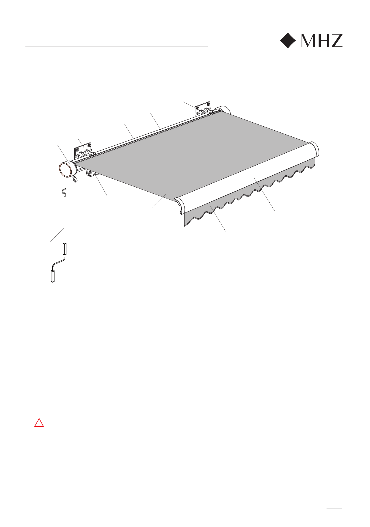
INSTALLATION INSTRUCTIONS
1. Awning fabric
2. Side cap
3. Wall bracket
4. Tube
5. Fabric tube
6. Arm bracket
7. Joint arm
8. Drop bar with end caps
9. Valance with binding
10. Crank handle
nova_02 tube awning
Check delivery at once for any
damage caused in transit.
The contents of the shipment must
be checked against the delivery
note.
Caution:
Supplied without
fastening materials.
The fasteners must be matched by
the fitter to the given installation
substructure.
Important:
The extraction forces for the
fastening screws must be defined
on the basis of 70N/m² related to
the awning fabric surface area.
Operating note:
An awning is a sunshade, not a shield
from all forms of weather.
In the event of wind, storms, snow or
rain, it must be retracted. If the awning
is equipped with an automatic
controller (e.g. wind and sun sensor),
this must be switched off over the
winter (danger of icing up).
Give the user of the awning the
accompanying operating instructions
and explain to them in detail all the
guidance on awning use and safety.
MHZ awnings require in the main no
maintenance. If any faults do arise, notify
your specialist retailer.
Required tools:
- Phillips screwdriver size2
- Allen wrench SW 2, 3, 4 + 6
- Box spanner SW 17
- SW8 socket wrench or SW8 socket
spanner with flexible shaft
- Spirit level
If electrically operated:
1 adjustment cable for SunTop drives
(prod. no. 99-1085) or
1 adjustment cable for RTS or io wireless
drives (prod. no. 99-4196) Adjustment
cables can be used only for the
installation!
Caution: For motor settings please follow
the setting instructions for electric drives,
p.19, 20 + 21.
Subject to technical changes - Edition 10.2020
!
175
20
20
150
203
22
4xø15
10
*
!
II
Subject to technical changes - Edition 10.2020
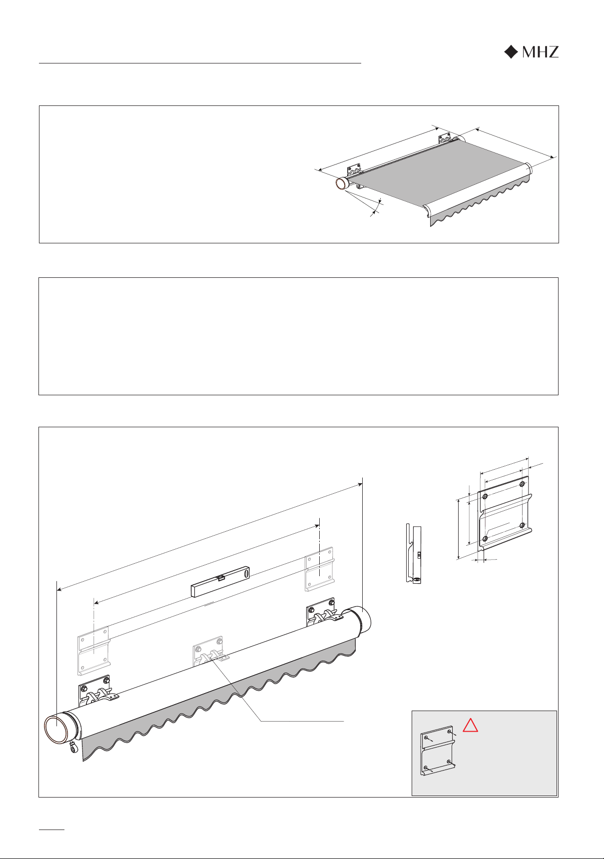
Unit width
Projection
* Pitch
Mark out the full awning width (unit width) on the wall or ceiling.
Specify the alignment with the guide (horizontal).
Measure the awning's centre-to-centre distance, i.e. the measurement from the centre of the arm bracket to the centre of
the arm bracket, and transfer to the awning width marked on the wall or ceiling. Align the brackets on the wall or ceiling
and attach with screws.
Caution: The brackets must always be aligned vertically and horizontally.
The fittings must be
suitable for the existing
installation substructure!
4 Fixing points
Technical data
Unit width: from 190 cm to 600 cm
coupled from 601 cm to 1200 cm
Projection: 150 / 200 / 250 / 300 cm
Arm bracket: pitch adjustable from 5° bis 28°
Type of installation: wall / ceiling / rafter
from unit width of 451 cm: Central support bracket
1. Attaching the brackets
1.1. Wall installation
nova_02 tube awning installation instruction
Arm bracket centre-to-centre distance
Unit width
A support bracket is
installed in the centre
of units with a width
of 451 cm and above.
11
15
16
17
A
MHZ
12
13
14
213
4x ø15
20 135
175
20 135
175
MHZ
A
18
19
11
!
!
II
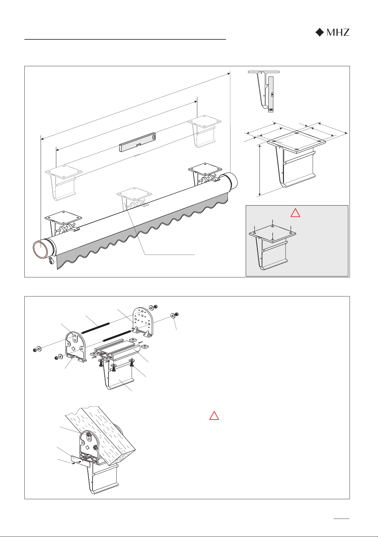
1.2. Ceiling installation
1.3. Roof rafter installation (accessory)
The fittings must be
suitable for the existing
installation substructure!
4 Fixing points
Using sliding block, hexagon head screw M10x25,
U-washer (12) and box spanner SW17, fix support
rail (11) to roof rafter bracket (13).
Push both plates (14) into the upper grooves of the
support rail (11). Mark top drill hole (A) on the rafter
and drill through using a ø12 mm drill bit.
Push through threaded rod (15) and screw in place at
both ends with washers and M10 nuts (16).
As shown at 1.2. Ceiling installation, align rafter
brackets with each other.
Drill second hole appropriate to the two plates and
screw in place. Then tighten threaded pin (17).
Then fix side panels (18) of the support rail in place
using 2, 4.2x16 slotted pan head screws (19) for each.
nova_02 tube awning installation instructions
Subject to technical changes - Edition 10.2020
Arm bracket centre-to-centre distance
Unit width
A support bracket is
installed in the centre
of units with a width
of 451 cm and above.
12
20
21
3
22
6
23
24
Subject to technical changes - Edition 10.2020
Horizontal
setting
Step 1
Step 2
nova_02 tube awning installation instructions
3. Dropping in the awning
4a. Setting the awning arms to be horizontal
Mount the awning in the bracket (3) using the arm
brackets (6) and attach to the brackets with the two
M8x25 threaded pins (22) (SW4 Allen key).
Note:
Always tighten the two outer threaded pins (22) on the
brackets first and then the inner ones.
If with the awning retracted the arms are not horizontal,
proceed as follows:
Extend the awning approx. 20 cm.
Loosen the M6x16 threaded pin (23) pointing towards
the centre of the awning in the arm bracket arm slot
(SW3 Allen key).
Move the arm into a horizontal position by tightening or
loosening the opposite outer threaded pin (24) in the
arm bracket.
Note: - Tightening the threaded pin:
Arm moves up
- Loosening the threaded pin:
Arm moves down
After adjusting the arms, both threaded pins (23, 24)
must be tightened again.
Extend and retract the awning and check the setting.
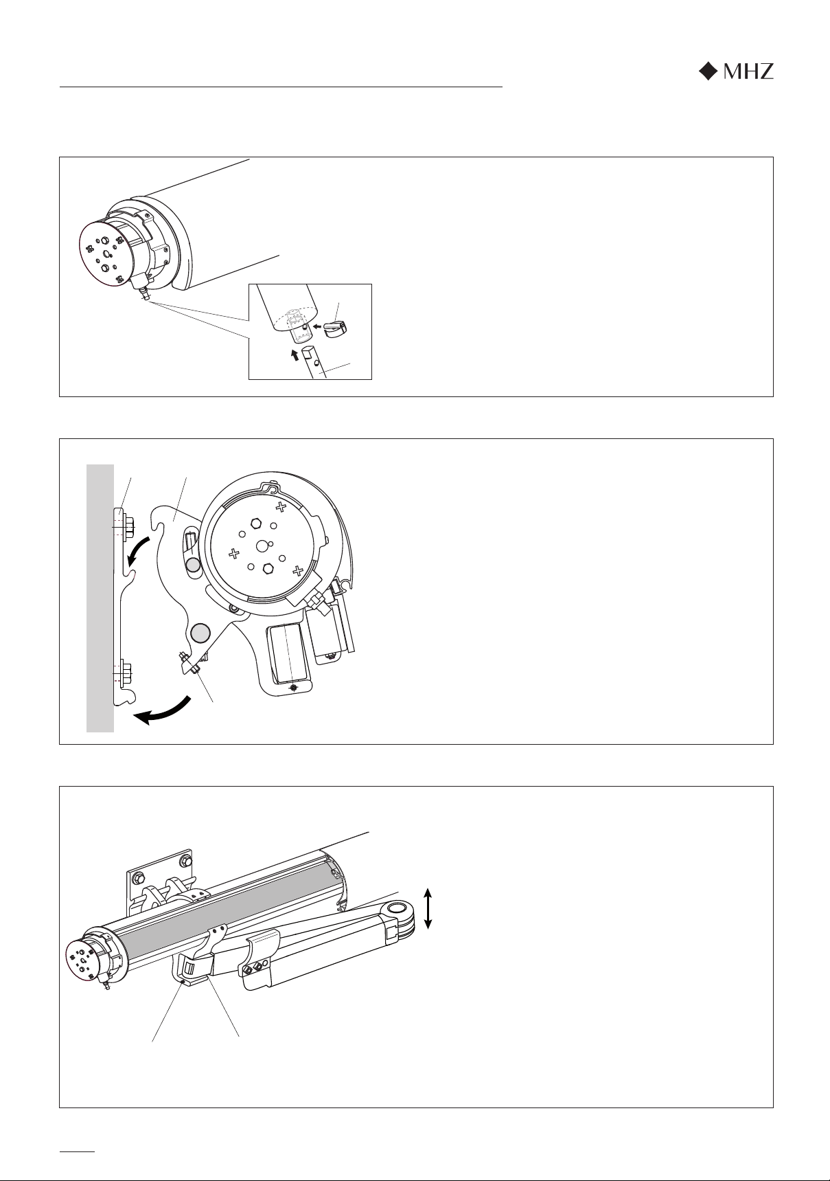
2. Installing the gear eyelet extension
Before mounting the awning in the brackets, the
extension for the connecting rod eyelet must be
installed.
Place the extension (20) in the bevel gear support
and secure with the locking bolt (21).

25
13
SW 2
29
28
2726
nova_02 tube awning installation instructions
If the arms tilt out towards the wall when the awning is
retracted (axial setting), proceed as follows:
Extend the awning approx. 10 cm.
To be able to centre the awning fabric in the drop bar,
loosen the threaded pin on the left and right of the
piping clip (25) (SW2). Loosen the cylinder head
screws (26) on the left and right of the suspension
bracket (27) using a SW6 Allen key.
Almost close the awning.
Centre the drop bar and awning fabric. Align the left
and right arm axially (place arm on the front arm
stop).
Mark the new left and right position of the suspension
bracket on the drop bar with a pencil.
Extend the awning approx. 10 cm.
Secure the cylinder head screws (26) in the new
position on the left and right of the suspension
bracket (27). Secure the awning fabric on the left and
right again using the piping clips (25).
Extend and retract the awning and check the settings.
Subject to technical changes - Edition 10.2020
4b. Aligning the awning arms by their axis
5. Pitch adjustment
Extend awning fully.
Use the SW8 Allen key (29) provided to twist the
spindle (28) until the desired incline is achieved.
Horizontally align the drop bar.
Tip: For easier adjustment of the pitch slightly
raise arms
Turning right = steeper pitch
Turning left = shallower pitch
Adjustment range of 5° - 28°
Installation tip:
SW8 socket spanner with flexible shaft
Axial
setting
14
9
30
32
31 8
33
2
35
34
36
Step 1
Step 2
Step 3
nova_02 tube awning installation instructions
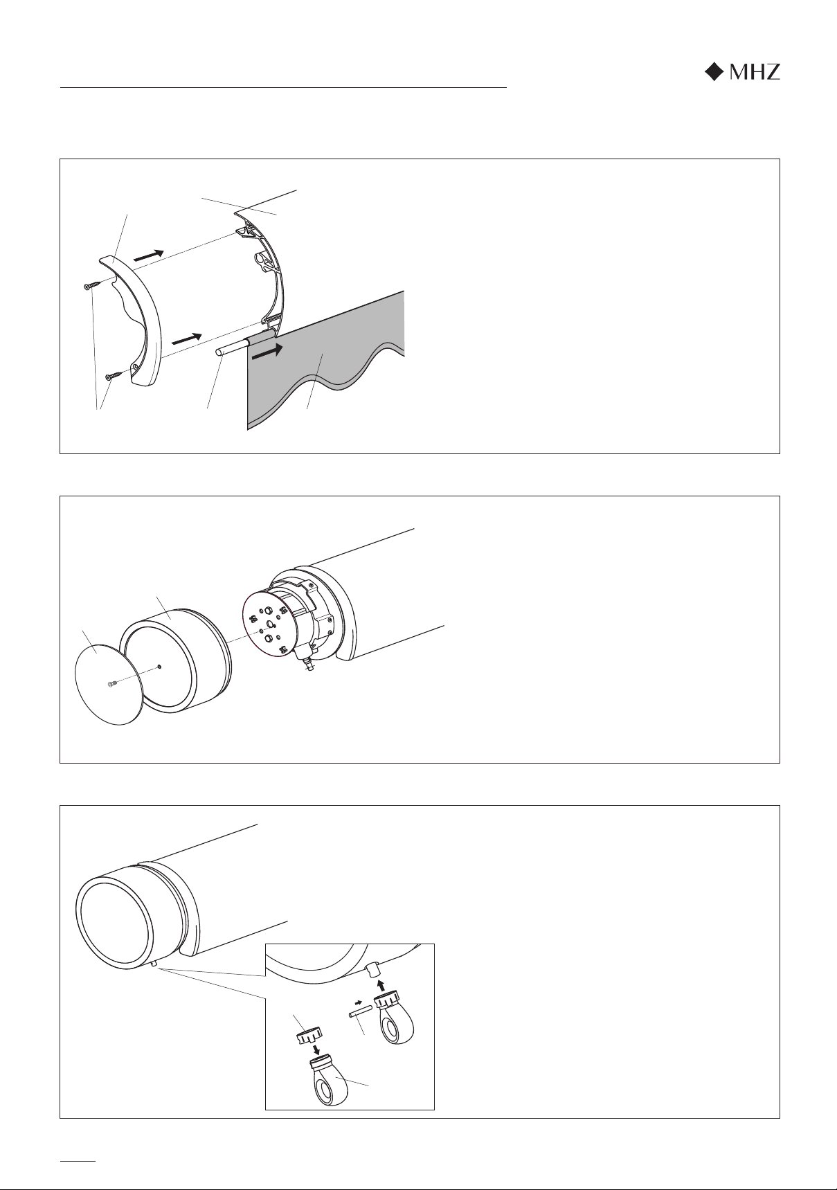
7. Side cap installation
Subject to technical changes - Edition 10.2020
8. Gear eyelet installation
Attach the side cap (2) and screw on to the tube ring
with the cover (33).
Push the retaining ring (34) on to the connecting rod
eyelet (35) and slide both on to the extension. Turn
the retaining ring and connecting rod eyelet into
position until the cylindrical pin (36) for securing the
eyelet on the extension can be inserted.
Remove the round piping from the drop bar. Insert
the round piping (30) into the valance (9). Always
push the valance into the groove on the drop bar (8)
from the right. Push the end cap (31) onto the drop
bar and secure with 3.5x19 countersunk screws (32)
and a size2 Phillips screwdriver.
Tip: To store the valance safely in the winter, loosen
the end cap and pull the valance out of the
drop bar. Then attach the end cap back on the
drop bar.
6. Valance
15
35
36 20
21
2
33
SW 4
37
35
2
20
34
!
nova_02 tube awning installation instructions
9. Gear adjustment
The gear's end setting is set at the factory. If you do,
nevertheless, want to change the end setting, proceed
as follows:
Extend awning until the free-wheel clutch activates
(clear 'click' sound). Then retract awning c. 1 to 2 cm.
Twist the retaining ring (34) on the connecting rod
eyelet (35) until the cylindrical pin (36) for removing the
connecting rod eyelet is visible. Remove the cylindrical
pin. Remove the side cap (2) after unscrewing the
cover(33).
To set the gearing, take off extension (20). Remove
bolt lock (21) and pull extension (20) out of the bevel
gear's mount.
Gear adjustment:
Using an SW 4 Allen key, loosen the internal securing
screw (37) by three rotations. Fit extension (20) and
plastic eyelet (35) again.
When adjusting the end stop outwards (projection
becomes greater):
Using the crank handle, slightly wind the awning in
(c. 1 cm) in order to take pressure off the end stop.
Then wind out to the desired end position.
This short movement prevents any damage to
the adjustment cogging.
When adjusting the end stop inwards (projection
becomes smaller):
Using the crank handle, wind the awning in to the
desired end position.
Take off eyelet and extension and tighten securing
screw (37) again.
Then fit extension (20), plastic eyelet (35) and
side cap (2) again.
Check setting by retracting by c. 50 cm and then
extending until the free-wheel clutch activates (clear
'click' sound).
Note:
Wind in UP direction (wall direction)
= projection gets smaller
Wind in DOWN direction (projection direction)
= projection gets bigger
Subject to technical changes - Edition 10.2020
Step 1
Step 2
Step 1
Step 2
39
40
41
42
43
38
39
40
41
42
38
44
38
16
nova_02 tube awning installation instructions
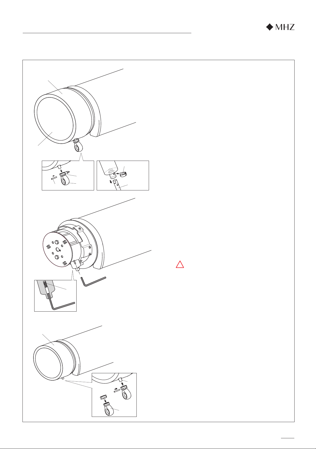
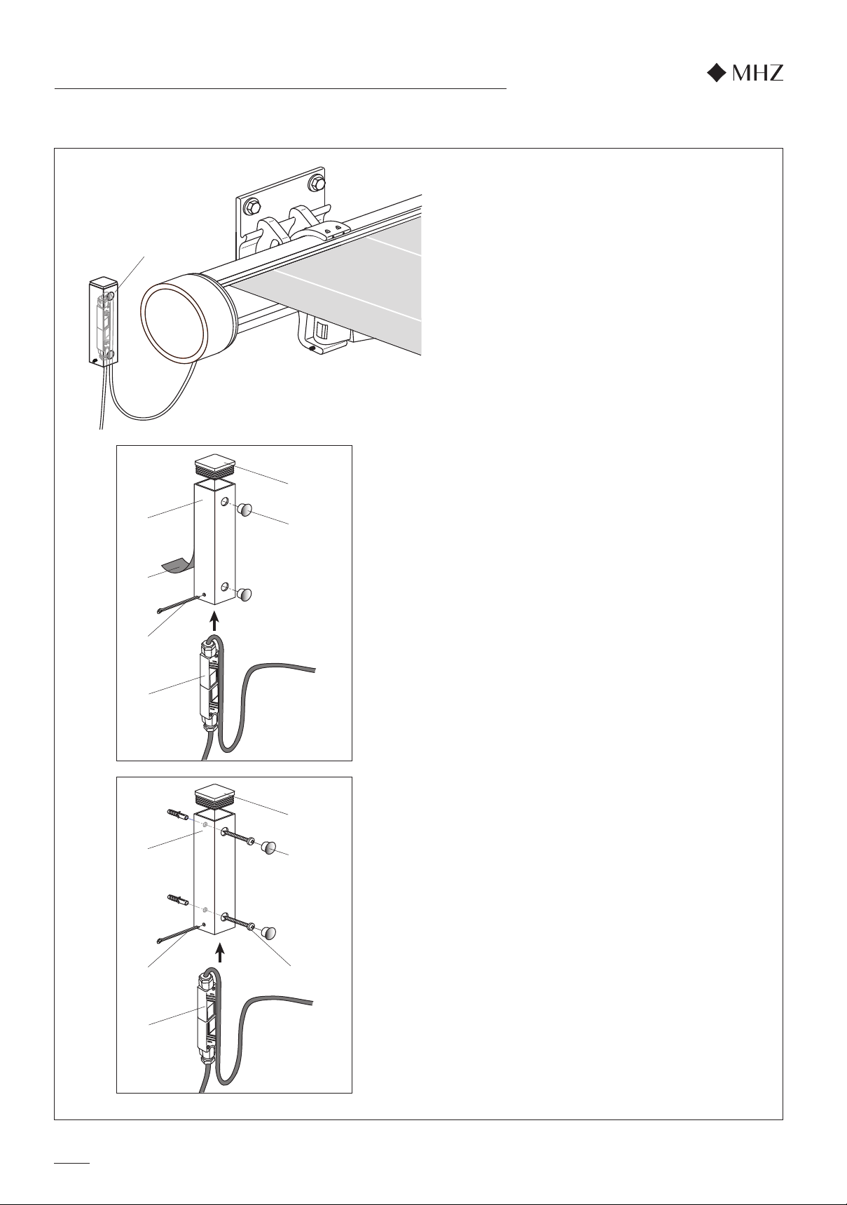
10. Protective sleeve installation for Hirschmann coupling (accessories)
Protective sleeve for Hirschmann coupling
(accessories)
The protective sleeve (38) for a Hirschmann coupling
can be screwed to the wall or ceiling. It should be
installed with the open side facing down. This ensures
that any incoming water or rain can drain away.
1. The protective sleeve can be secured to even and
smooth surfaces, such as a powder-coated carrier
bar, coated metal, and to stable and smooth plastic
substructures using adhesive.
Substructures such as plaster, concrete or wood,
and structured substructures, are not suitable for
adhesive.
Insert the plug-in caps (39) at the top of the
protective sleeve (38). Insert the two decorative
plugs (40) into the unused holes. Insert the
Hirschmann plug (41) into the protective sleeve
from below and secure with the splint (42).
Remove the protective film from the adhesive tape
(43) on the back of the protective sleeve. Stick the
protective sleeve in the required position on the
designated substructure and press down firmly
2. Screw fitting
Insert the plug-in caps (39) at the top of the
protective sleeve (38). Attach the protective sleeve
to the wall or ceiling using the S6 dowel and a
ø5x50 chipboard screw (44). Then insert the two
decorative plugs (40) into the holes.
Insert the Hirschmann plug (41) into the protective
sleeve from below and secure with the splint (42).
Step 1
Step 2
Step 3
Step 4
Step 1
Step 2 Step 3
Step 4
Subject to technical changes - Edition 10.2020
51
8
8
17
6
3
45
47
48
46
50
4950
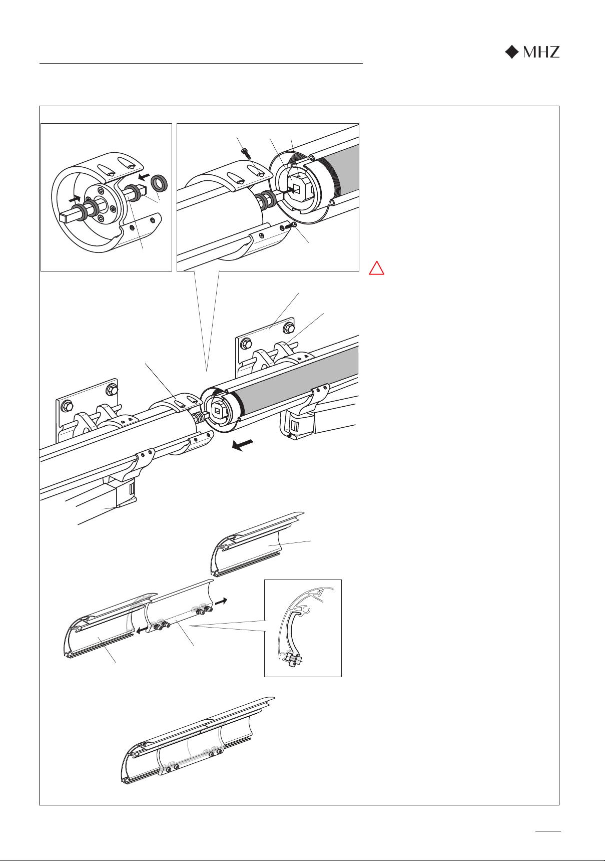
nova_02 tube awning installation instructions
11. Coupling
Caution:
Only remove the arms' securing tapes after the
fabric tube's coupling.
Here is a lot of tension on the joint arms -
Risk of injury!
Install the awning section with the drive in the
same way as a single unit. Hook the joint arm
brackets (6) of the field, that is being connected, in
to the brackets (3) and push on to the coupling
bracket (45).
1. Connecting the fabric tube
Push the two spacers (46) on to the coupling
square (47). The fields, that are being connected,
must have the same number of fabric layers and
the piping channels on the fabric tubes must be
aligned.
When sliding on the field, that is being connected,
the coupling square (47) must be pushed into the
fabric tube insert (48) on the field being
connected. Do not forget the spacers (46). Press
the tube together gently and push into the
coupling bracket (45).
Secure the square with the threaded pin (49)
(SW3). Fix in place with a 3.9x14.5 countersunk
self-tapping screw (50) and a size2 Phillips
screwdriver.
2. Secure the connected awning section to the
brackets using the threaded pins on the arm
bracket (see installation instructions p.12, point3)
(SW4 Allen key).
3. Remove the retaining straps from the joint arms.
4. Extend the awning fully.
Check that the drop bars for both fields are at the
same height horizontally. If they are not level,
proceed as described in the installation instruc-
tions, p.13 “Tilt setting”.
Important for tension-free installation!
5. Retract the awning.
Check the fabric spacing. The spacing to the left
and right of the coupling bracket must be the
same.
Adjust if not.
6. Extend the awning fully.
7. Connecting the drop bar
Push in the top connector profile with the sliding
block (51) facing downwards until it is halfway into
the drop bar (8) groove. Then repeat this process
for the drop bar that is being connected. Align the
connector profile in the centre and screw tight
(SW6 Allen key).
8. Push the valance into the drop bar groove. Push
the end cap onto the drop bar and secure with
countersunk screws.
Subject to technical changes - Edition 10.2020
!

1.) 2.) 3.)
5.)
4.) 6.)
19
102
Winding
thermostatt
Electronics
Junction box
Switch box
Capacitor
Activation
button
L1
N
PE
Mains 230 V/50
Black
brown
blue
green/
yellow
3 1 42
Adjustment instructions for Elero SunTop drives
Subject to technical changes - Edition 10.2020
nova_02 tube awning installation instructions
A. Note for the electrical installer
This awning must not be connected with the power live. Take fuse out beforehand!
There is a risk of the electronic end position setting being deleted. Resetting this is possible
only with the special Elero setting cable (prod. no. 99-1085).
The system is to be protected with an upstream FI circuit breaker in accordance with
VDE regulations. Only cables and connectors with a protection class of a minimum of
IP 54 may be used to supply power
B. Important Notice
This unit is fitted with an electronic SunTop motor. The special Elero setting cable has to
be used to set the end positions. A conventional test cable can be used to operate the
unit, but not to set it!
The electronics within the drive unit function only when built into the fabric tube!
Work on the mains power may be carried out only by authorised specialists!
After setting the drive's end positions, secure these installation instructions to the cable
for the electrician!
When using your own control systems not included with the product (e.g. wind/sun sensors
or similar), you must ensure that a switch-over pause from retract to extend command of at
least 0.5 seconds is set in the controller.
Where operation is via switches, only push-button switches with a 'dead-man' circuit are
permissible and they must mutually disable each other.
In accordance with VDE regulations, the motor may not be supplied with continuous current.
Otherwise the SunTop drive cannot be guaranteed to function reliably!
Note: It is possible to connect multiple SunTop drives in parallel (max. 430 W per drive).
If doing so, pay attention to the switching point's maximum switching capacity.
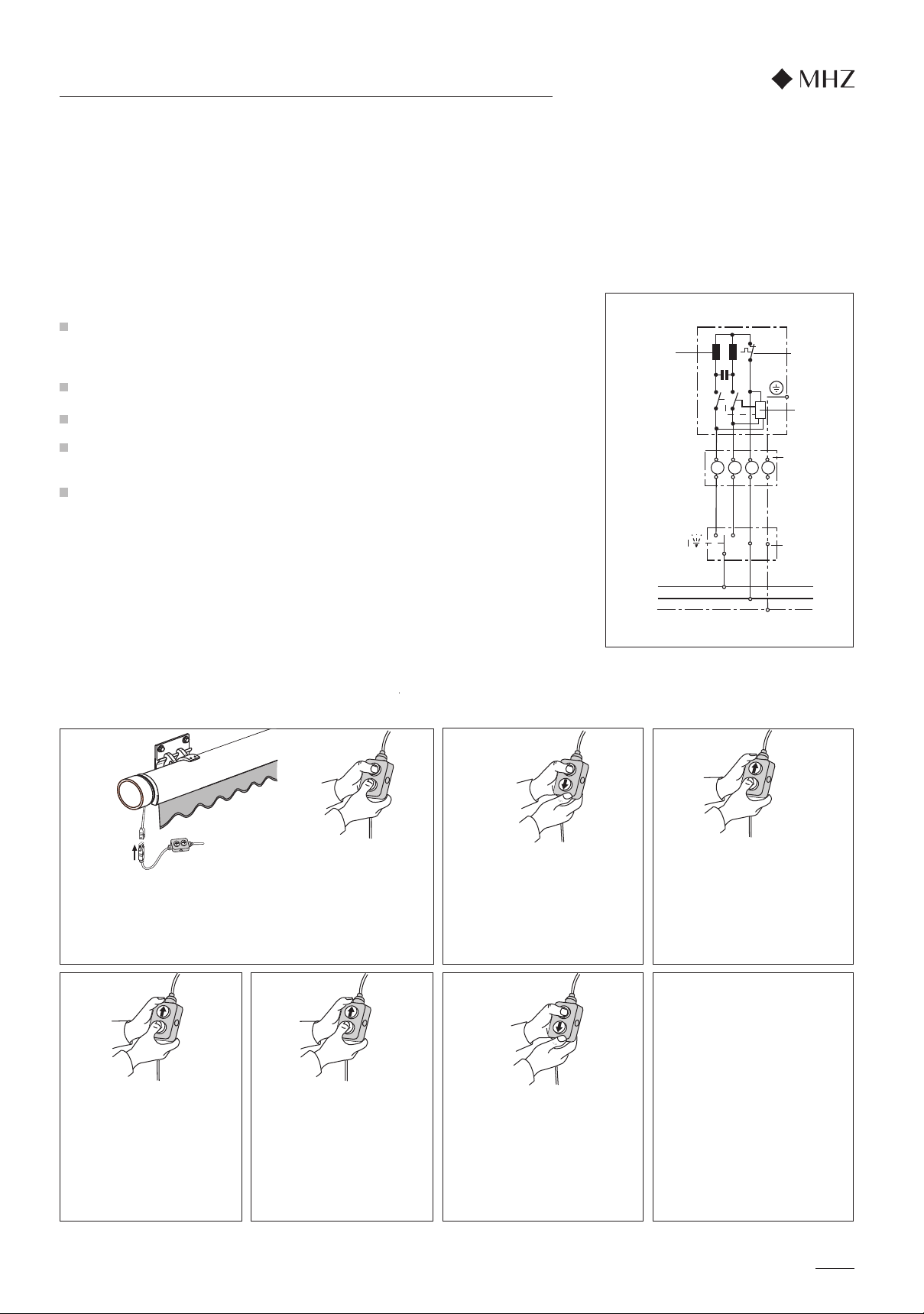
D. End position setting
The end position setting of the SunTop drive is set at the factory and does not normally need any correction. If you do,
nevertheless, want to set the drive's end positions differently, please note the following points:
C. Connection example
Press the DOWN button until the
drive automatically stops.
The top end position has now
been set.
Press the DOWN button again.
Run out the awning to just
before the desired bottom end
position. The drive starts with a
short STOP.
Move to the desired bottom
end position.
Corrections can be made via
the buttons.
The end positions are now set as
wished and the drive moves into
the respective end position.
Connect the Hirschmann
coupling to the control line again.
With this new drive there is no
need to simultaneously press the
UP and DOWN buttons after
resetting the end positions.
Pressing both buttons simulta-
neously would put the drive back
into programming mode (see
point 1).
Connect the Elero setting cable to the drive's Hirschmann coup
ling and run the unit out 30 cm. At the same time, press both
buttons on the setting cable. After c. 5 seconds, the drive goes
briefly up and down. The end positions have now been deleted
and can be reset.
Press the UP button again. Move
up to the top end stop. When the
stop is reached, the drive auto-
matically switches off.
Press the UP button until the drive
automatically stops.
The bottom end position has now
been set and the programming
finished.

s mfy
my
123
20
Up
Product no. 99 - 4196
In order to be able to operate the awning during installation, the drive must be connected to the Somfy
test cable. For power to be supplied to the drive, the test cable's 'Up' button has to be pressed.
The drive can then be operated via the hand-held radio remote control unit supplied with it.
The remote control unit has been paired with the drive. The top and bottom default end positions have
also been set at the factory and do not need any further programming. In the top end position the drive
automatically switches off when it reaches a set level of rated torque.
1. On the back of the transmitter already paired
with the radio-controlled drive press the
PROGramming button for c. 2 seconds.
The unit briefly moves and is thus 'Ready for
Pairing'
2. Briefly press the PROGramming button of the
transmitter to be newly paired (or deleted).
The unit again moves briefly back and forth.
3. The new transmitter has now been paired
(or deleted).
4. Trial run
1. Via the 'DOWN' button, extend the awning
completely (drive switches off automatically).
2. Press the 'UP' and 'DOWN' buttons simul-
taneously for c. 5 seconds until the unit
briefly moves back and forth.
3. Via the 'UP' or 'DOWN' buttons set the
awning's new, desired end position.
4. Press the middle 'Stop' button until the unit
again briefly moves back and forth.
5. The bottom end position has now been
reprogrammed.
6. Trial run
blue
( N ) black
( L1 )
empty
green/yellow
( PE )
Electrical connection
Pair further transmitters
(Or delete paired transmitters)
A maximum of 12 transmitters (including a maximum of 3 Sensor RTS
transmitters) can be paired with the OREA RTS radio-controlled drive.
In order to pair further transmitters (or to delete them), you always need a
transmitter that has already been paired.
If no such transmitter is available to you, contact your specialist retailer to
get further information.
The OREA RTS must be connected according
to the terminal assignments.
When making connections ensure that there is
no supply of power.
(Remove the fuse!)
Note: An electrician must perform the on-site
connection of drive system and controller.
Up / On
Stop
Down / Off
Back
Installation
NB: The awning's end positions are set at the factory. No alteration is necessary unless you want to
reset the bottom end position.
PROGramming
button
Adjustment instructions for OREA RTS drives from Somfy
nova_02 tube awning installation instructions
In order to prevent water running
along it into the motor, the connection
cable should always be laid with a
downward loop.
The system is to be protected with an upstream FI circuit breaker in
accordance with VDE regulations.
Only cables and connectors with a protection class of a minimum of
IP 54 may be used to supply power.
Subject to technical changes - Edition 10.2020
Special features of radio control systems
Features of the radio transmitters
Radio control systems' range is limited by the statutory regulations for wireless equipment and the
structural circumstances.
The control system should not be installed in the immediate vicinity of any metallic surfaces. Strong local
transmitter units (e.g. wireless headphones) that have a transmission frequency identical to the control
system can have an influence on its function. The transmission range is up to 300 metres in the open and
c. 20 metres inside buildings. The operating instructions of the Somfy radio transmitters being used must
be followed.
All suitable Somfy radio transmitters can be paired with and operate the OREA RTS drive,
e.g.: Telis 1 RTS, Telis 4 RTS, Telis Soliris RTS, Centralis RTS.
A maximum of 12 transmitters (including a maximum of 3 Sensor RTS transmitters) can be paired
with each OREA RTS drive.
Changing the lower end position
(Only necessary if the factory setting is to be altered)
The top and bottom end positions are set at the factory and do not
normally need any further programming.
If necessary, the bottom end position can be changed (the top end
position always stays the same).T.
Table of contents
Other MHZ Lawn And Garden Equipment manuals


