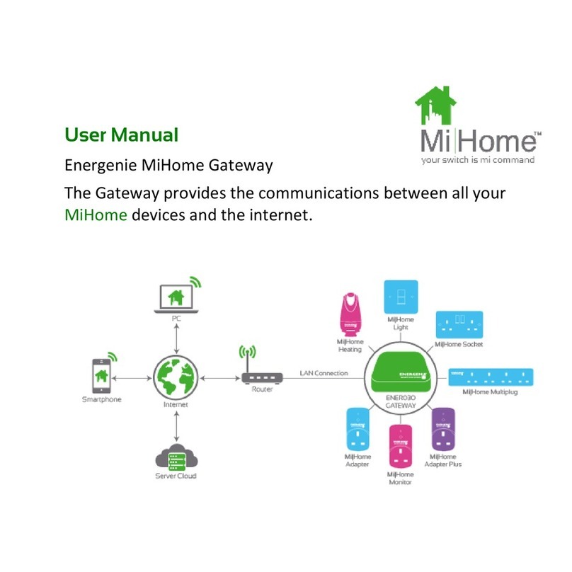
Mi Home MIHO001 User manual

Mi
Home
™
Mi|Home System Overview
The MiHome system integrates control and monitoring of lighting, heating, mains power
switching and sensor devices for the home using the MiHome App (iOS & Android) or
from any web browser. The devices incorporated into the MiHome system include: light
switches, mains switching devices, power monitors, heating controllers and sensors. The
user can manually control these devices and also set up timers and use simple logic
triggers for control including the IFTTT system available on the internet. This guide will
walk you through the elements of the system.
Essential
Esse
n
Es en
Esse
n
Essen
Esse
Essen
Es
s
e
Essen
Esse
Essen
Es
s
e
n
Es en
Es
s
en
Es
s
en
Es
s
en
Es en
Es
s
e
Es
s
en
Es
s
en
Essen
Es
s
n
2
Mi|Home
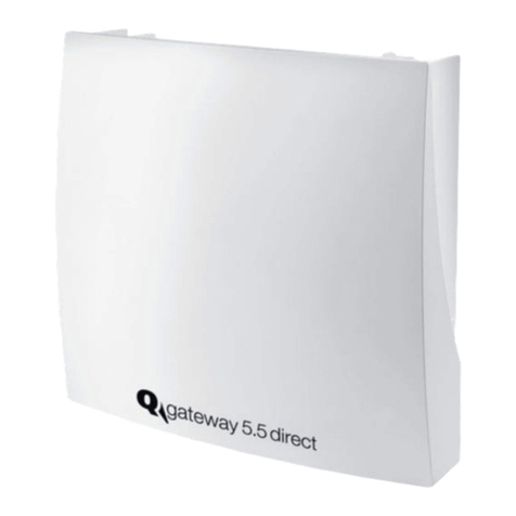
Gateway
Energy
Monitor
Adapter
Heating
Adapter
Plus
House
Monitor
Relay
Multiplug
Light
Socket
Motion
Sensor
Open
Sensor


Mi|Home Lighting Controls (MIHO0 08, MIHO0 24,
MIHO0 25, MIHO0 26)
The Mi|Home lighting range consists of a single switch, master and
slave switch, double wall switch and a dimmer. All switches are available
in White, Polished Chrome, Brushed Steel and Black Nickel. The range
includes screwless replaceable face plates. All switches are retroî t in
suitably deep pattress boxes (25mm depth or deeper).
FAQs about the Light Switches
Are the switches retroî t? Yes
What is the maximum load they can switch? The switches are capable of
switching up to 250W.
Do the switches work with LED bulbs? Yes, however we recommend that
you have at least two LED bulbs in series and use quality, dimmable LED
bulbs with the system. We have tested leading UK brands successfully.
Do the switches î t in 25mm pattress boxes? Yes, though top and bottom
lugs must be removed.
Do the Switches require a neutral wire? No, they switch live only.
Do the switches feedback status? No
Slave
MIHO0 0 8 Light Switch & Slave Switch
Fitting and Wiring Instructions
1). Before commencing work, isolate the mains power supply and remove the fuse in the fuse box or switch oǺ the circuit breaker in the
consumer unit.
2). If unit is to be used as a replacement for an existing product, remove existing unit from its location and disconnect the wiring.
3). This item will not î t into a 4 lug box. If such a box has been previously installed the top and bottom lugs should be removed or bent back to
avoid contact with the interior.
4). Connect the wires as shown in appropriate wiring diagrams above. Use green/ yellow sleeving on earth conductors that are not insulated.
Ensure terminals are properly tightened and no bare wire is visible. Push back unit into mounting box making sure conductors are not trapped.
5). Screw the unit module to the mounting box, please ensure screws are suǸ ciently tight to support the product but please do not over tighten
as this may cause some deformation.
6). If the product has a decorative front cover plate over the module, place the cover plate over the module and press î rmly top and bottom
until all retaining clips have fully clipped into position. To remove the decorative front cover plate, carefully insert a 3mm terminal screwdriver
into the bottom slots and lift upward until all the retaining clips disengage from the plastic module moulding. Please ensure the decorative
plate is held as it is released to avoid it being dropped and damaged.
7). To reduce the risk of discolouration or tarnishing, avoid installation on damp plaster.
8). These products must be installed in accordance with the latest Building and IET
wiring regulations. If in any doubt, please contact a qualiî ed electrician.
7
Typical Application 1 Way Switching
250 W RF Switch
Typical Application 2 Way Switching
(Appropriate RF Slave switch
must be wired for this application)
250 W Switch
MASTER
MASTER
SLAVE

Mi
Home
™
LN
220-240V ~50Hz
Max. 13A µ
Resistive Load
Frequency 433.92 MHz
BS1363
Link to Earth
Terminal in
metal box
Mi
Home
™
MiHome Double Wall Sockets
Fitting and Wiring Instructions
1). Before commencing work, isolate the mains power supply and remove the fuse in the fuse box or switch on the circuit
breaker in the consumer unit.
2). If unit is to be used as a replacement for an existing product, remove existing unit from its location and disconnect the
wiring. The back box will need to be at least 35mm deep
otherwise the original will need to be replaced.
3). This item will not t into a 4 lug box. If such a box has been previously installed the top and bottom lugs should be
removed or bent back to avoid contact with the interior.
4). Connect the wires as shown in appropriate wiring diagrams above. Use green/ yellow sleeving on earth conductors that
are not insulated. Ensure terminals are properly tightened and no bare wire is visible. Push back unit into mounting box
making sure conductors are not trapped.
5). Screw the unit module to the mounting box, please ensure screws are suǸ ciently tight to support the product but please
do not over tighten as this may cause some deformation.
6). If the product has a decorative front cover plate over the module, place the cover plate over the module and press î rmly
on the top and bottom until all retaining clips have fully clipped into position. To remove the decorative front cover plate,
carefully insert a 3 mm terminal screwdriver into the bottom slots and lift upward until all the retaining clips
disengage from the plastic module moulding. Please ensure the decorative plate is held as it is released to avoid it being
dropped and damaged.
7). To reduce the risk of discolouration or tarnishing, avoid installation on damp plaster.
8). These products must be installed in accordance with the latest Building and IET
wiring regulations. If in any doubt, please contact a qualiî ed electrician.
Typical Installation
9
L N

Mi
Home
™
11
Single Pole Relay
MiHO0 14 Single Pole Relay
Fitting and Wiring Instructions
1) Before commencing work, isolate the mains power supply and remove the fuse in the fuse box or switch oǺ the circuit breaker in
the consumer unit.
2) Connect the wires as shown in the wiring diagram attached. Ensure the cables are stripped to an appropriate length of between
6mm and 10 mm. Ensure the cables are fully inserted into the
terminals and that the terminals are properly tightened and no bare wire is visible.
3) Screw the unit to a suitable ï at vertical surface at least 400 mm above the adjacent ï oor.
4) This product must be installed in accordance with the latest Building and IET Wiring
Regulations by a suitable competent person. If in any doubt, please contact a qualiî ed electrician.
For indoor use only


Mi
Home
™
Mi|Home App features
The Mi|Home App is available for Apple iOS and Android devices from the appropriate App store. It
has a variety of features these include the following:
Simple Switching:
Switch actuators from anywhere in the world and set them on the move.
Timers and Programmes:
Set up timers and programmes for actuators to turn on and oǺ at
diǺerent times and days of the week. It also allows you to set heating by
temperature and time.
Energy Monitoring:
Display accumulated historical energy data from both the Monitor adapter
and Whole House Monitor.
Geofencing:
Control actuators via the location of your phone. For example, automatically turn oǺ
lights when you leave home or switch on your heating when you get close to home.
Linking:
Link sensors to actuators so that a motion sensor can automatically switch on lighting
when you enter a room or turn oǺ radiators when a window opens.
Alerts:
Receive an alert when your smoke alarm sounds, when motion is detected or a door is
opened for example.
Schedule
Outside Light
M
i
a
A uic lin to our scheduled
acti ities allo ing ou to pause
timers ith one press
Mi nerg
Monitor the energ usage in real
time or o er time o indi idual
soc ets groups or scenes
M
i
a
o
u
r
i
t
e
s
ic our a ourite or most
used products groups or
scenes or uic access
Mi outines
Set up timers or indi idual
products groups or scenes
Mi|Home
Outside Light
Outside Light
Outside Light Timers
Outside Light Timers
Outside Light
14

Service Model
Service model for installers: Providing a fully working handover, beyond installing.
The system should be looked at as a service opportunity and oǺered as more than just an
installation:
This would include but not be exclusive to:
• Setting up of user account, credentials, tariǺ information and Gateway
• Pairing of all devices
• Naming of all devices
• Grouping of all devices [if speciî ed by customer]
• Walk-though of timer setting
• Walk-through of Geofencing setting
• Tour of browser, including password recovery, change password, change tariǺ etc.
Due to the simplicity of the system this will be start forward but will give you the conî dence
that there will be no post install calls and will give the user conî dence that the system is
working and has been installed correctly. This should be seen as a chargeable service.
There is also the opportunity to oǺer an annual maintenance visit. This will also oǺer an
opportunity to up-sell new additions to the Mi|Home range, but as a minimum cover:
• Renaming of any devices
• Modiî cation of any timer-related issues
• Modiî cation of tariǺ info if required
• Fully open/ close each valve
• Change valve batteries
• Test any sensors [door/ PIR/ smoke]
Mi
Home
™
16
Other manuals for MIHO001
1
Table of contents
Other Mi Home Gateway manuals
