Miatech Bio Turbo 100 User manual
TECHNICAL INSTRUCTIONS
Bio Turbo 100 User Guide
Specication Sheet ..........
Installation Guide. ...........
Layout Diagram. .............
Maintenance Guide ..........
Wiring Diagram..............
Pull Sheet ..................
JAN ,
AIRBORNE BACTERIA & ETHYLENE REMOVAL

MIATECH TECHNICAL INSTRUCTIONS | BIO TURBO USER GUIDE SPECIFICATION SHEET | JAN ,
Features
• LED lights for quick diagnostics
• Easy service
• Easy changing of ozone plates and lters
• Four models for proper coverage
• Aluminum and Stainless Steel
generation chamber
• Easy to install and operate
• Low maintenance
Model(s) Bio Turbo
Maximum volume up to ³ ( m³) per hours
Airflow CFM (. CMM)
Location Requirements
Electrical Source - VAC
Circuit Breaker A
Maintenance
Air Filter Change every months
Ozone Plate(s) Change every months
Number of Ozone Plates
Specications
Size:
Height inches ( cm)
Width inches ( cm)
Depth inches ( cm)
Weight lb ( kg)
Construction
Materials:
Unit Cabinet Aluminum
Perforated Generator Plate Stainless Steel
Controls
Remote Control: N/A
Power Switch
Bio Turbo 100
Specication Sheet

MIATECH TECHNICAL INSTRUCTIONS | BIO TURBO USER GUIDE INSTALLATION GUIDE | JAN ,
DESCRIPTION
The Bio Turbo is referred to, as the BT . The indicates
the amount of Cubic Meters the unit can properly control within a
hour period. The BT was designed to remove ethylene from cold
rooms and storage areas where fruits and vegetables are stored in
order to exteng their storage life.
TECHNOLOGY OVERVIEW
STAGE : AIR FILTER
The air lter removes dust and visual particles from the air.
STAGE : CELL DISRUPTER
An anti-microbial chemical is applied to the surface of a specically
designed substrate. This combination pierces and ruptures cell
membranes of airborne pathogens as they pass by, stopping the
normal life development of the cells. This stage can be especially
eective at controlling spores.
STAGE : OZONE CHAMBER
This chamber uses the positive eects of ozone to eliminate ethylene
gas while destroying up to .% of the bacteria and pathogens that
are being broken down during the previous stage. The ozone is safely
contained within the chamber providing a safe work environment.
STAGE : BIO CLEAN MODULE
In this nal stage, a catalyst is used to change the ozone into clean
oxygen. The catalyst creates a reaction that breaks down the ozone
molecule. From here the clean oxygen is released back into the
environment.
SYSTEM PLACEMENT
The Bio Turbo is constructed to be mounted to the ceiling or on
the wall as high as possible. Since ethylene is lighter than air it will
rise toward the ceiling.
There are four snap clips on the sides for securing the system to its
holding frame that can be easily installed
to the ceiling (see picture ).
Before drilling inspect the area where
the system will be mounted for any
obstructions that could be damaged.
Use the supplied screws to attach the holding
frame to the ceiling. Aer the holding frame
is installed you can easily secure the system
to its frame.
OPERATION
Picture 2
Aer supplying the power in to the system, “Breaker” LED should
be glowing green. This shows that power is to the system and the
circuit breaker is good.
Turn on the power switch. Three more LED’s should come “ON”.
These indicate there is power to the transformer, power to the fan
and to the ozone generator plate (a low hum should be detected
aer the unit is plugged in) (see picture ).
COUNTDOWN SERVICE TIMER
System is equipped with the Service Timer which is counting down
days to the next maintenance when system is operating. Timer
is set to days and when it gets down below days it starts
beeping and Service Red LED light on the system will flash, signaling
maintenance is due. Service Timer has to be reset back to days
aer maintenance is completed (see maintenance guide page for
further instruction).
: Please apply the BT Facility Entrance Label #25070, supplied in
a pack with system, near the facility entrance (see picture 3).
Bio Turbo 100
Installation Guide
Picture 1
www.miatech.org www.bio-turbo.com
This storage is protected
with Miatech’s Bio Turbo.
Ethylene and bacteria removal technology.
KILLS BACTERIA HUMAN SAFEREMOVES ETHYLENE
Picture 3

MIATECH TECHNICAL INSTRUCTIONS | BIO TURBO USER GUIDE LAYOUT DIAGRAM | JAN ,
Bio Turbo 100
Layout Diagram
BIO TURBO
Toll Free in North America:
1-800-933-6478
www.miatech.org
USA – phone: 1-503-659-5680
Fax: 1-503-659-2204
November 2010
THE ADVANTAGE COUNTS
BIO TURBO 100
LAYOUT DIAGRAM v. 1.1
MIATECH TECHNICAL INSTRUCTIONS | BIO TURBO USER GUIDE MAINTENANCE GUIDE | JAN ,
Bio Turbo 100
Maintenance Guide
:
ALWAYS UNPLUG POWER BEFORE SERVICE!
Maintenance Requirements
Annual service requires the replacement of Air Filter
(more oen if environment is very dusty) and the
replacement of the Ozone Generation Plates.
To replace the Air lter and the Ozone Generation
Plates:
• Disconnect the unit’s power cable.
• Unscrew the system lid.
• Remove and replace the air lter (#).
• To replace the Generator Plate (#) release from
the holder, remove and replace with new one.
System is equipped with the Service Timer (#) which
is counting down days to the next maintenance when
system is operating. Timer is set to days and
when it gets down below days it starts beeping and
Service Red LED light on the controller box will flash,
signaling maintenance is due. Service Timer has to be
reset back to days aer maintenance is completed.
To reset the Service Timer:
Carefully press and hold the button for about sec.
until numbers will start flashing. By releasing and
pressing again the same button select from
the options. Wait until it is dened (numbers will
stop flashing).
: a blunt object should be used to reset, so damage
won’t occur to the timer.
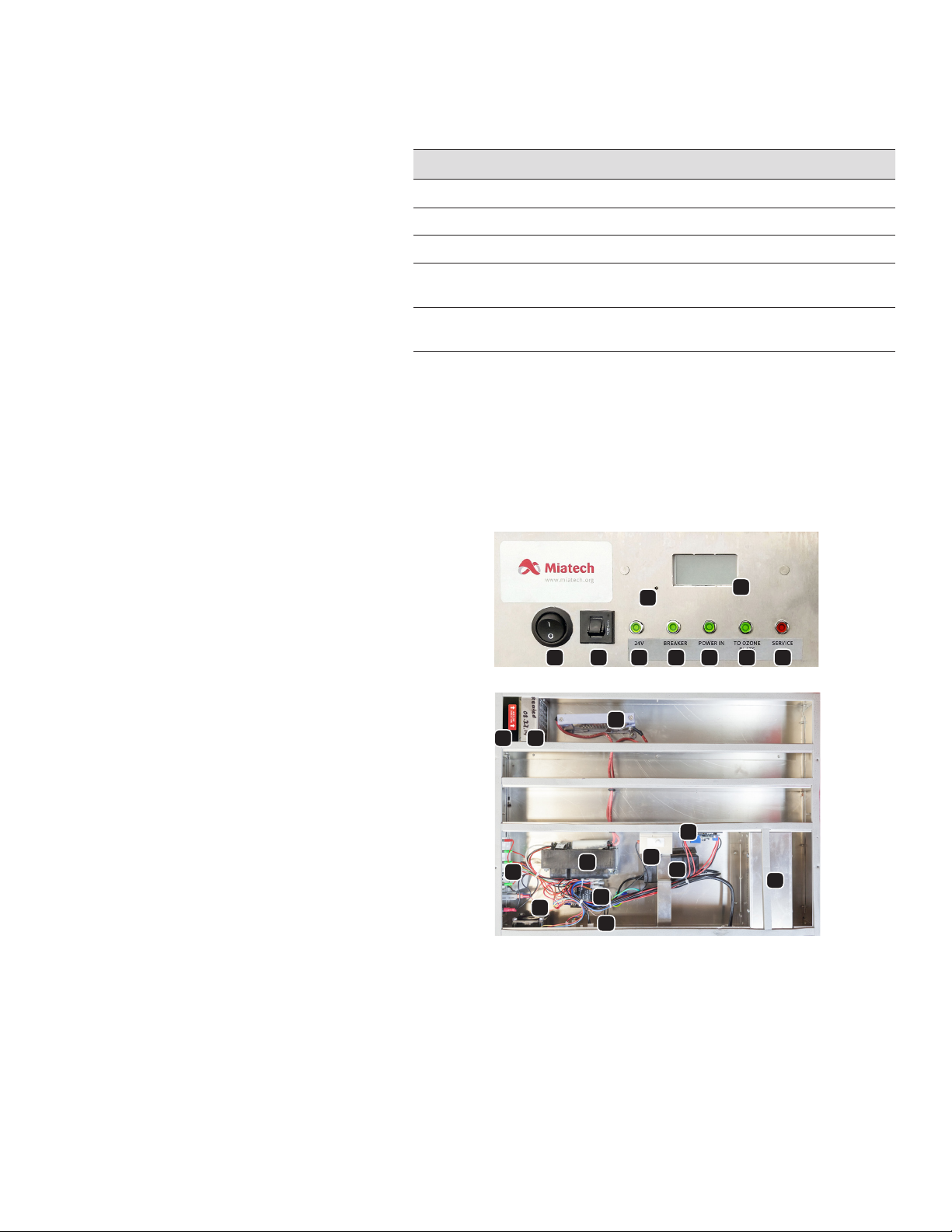
. Power Switch (#)
. A Breaker (#)
. V LED (#)
. LEDs V (#), V (#)
. Service V LED Red (#)
. Air Filter (#)
. Cell Disrupter (#)
. Generator Plate (#)
. Door Switch (#)
. Ozone Transformer (#)
. BT Service Timer (#)
. Solid State Relay (#)
. Fan V DC (#)
. Alarm Board for Fan (#)
. Transformer
V (#) / V (#)
. Catalyst Container
. BT Fuse Board (#)
. Timer Reset Hole
Diagnostic LED’s Name Description
“Breaker” (on the Controller Chamber) Power to the Unit
“Power IN” (on the Controller Chamber) Power to the Power Supply
“ V” (on the Controller Chamber) Power to the Fan
“To the Generation Chamber”
(on the Controller Cha mber)
Power to the Generation Chamber
“Service” (on the Controller Chamber) When the service is needed or when
protection has triggered
: If service Red LED comes ON along with strobe light, and timer is showing
more than 10 — the ozone generation current protection might be triggered. This
could happen due to the damage of ozone plates or power jump in power supply
network. Unplug the system and check the ozone plates. If this happened because
of power jump — restart the system by switching it OFF on a remote control and
put back ON aer 30 seconds.
Table of contents
Other Miatech Air Cleaner manuals


