Miatech Bio Turbo 100i Owner's manual
SPECIFICATION SHEET | MAR ,
TECHNICAL INSTRUCTIONS
Bio Turbo 100i User Guide
Specication Sheet ..........
Installation Guide. ...........
Layout Diagram. .............
Maintenance Guide ..........
Wiring Diagram..............
MAR ,
AIRBORNE BACTERIA & ETHYLENE REMOVAL

MIATECH TECHNICAL INSTRUCTIONS | BIO TURBO I USER GUIDE SPECIFICATION SHEET | MAR ,
Features
• Smart LED’s for easier service
• Easy service
• Easy changing of ozone plates and lters
• Four models for proper coverage
• Aluminum and Stainless Steel
generation chamber
• Easy to install and operate
• Low maintenance
Model BIO TURBO i
Maximum volume up to ³ ( m³) per hours
Airflow CFM (. CMM)
Location Requirements
Electrical Source V AC
Circuit breaker A
Maintenance
Air Filter Change every months
Ozone Plate(s) Change every months
Number of Ozone Plates
Specications
Size:
Height inches ( cm)
Width inches ( cm)
Depth inches ( cm)
Weight lb ( kg)
Construction
Materials:
Unit cabinet Aluminum
Perforated Generator Plate Stainless Steel
Controls
Remote control: N/A
Power Switch
Bio Turbo 100i
Specication Sheet
MIATECH TECHNICAL INSTRUCTIONS | BIO TURBO I USER GUIDE INSTALLATION GUIDE | MAR ,
DESCRIPTION
The BT i was designed to remove ethylene from cold rooms and
storage areas where fruits and vegetables are stored, extending the
life of the stored produce.
System can cover up to m³ per hours. It is designed to
operate continuously.
SYSTEM PLACEMENT
The Bio Turbo i is constructed to be
mounted to the ceiling of the truck. Since
ethylene is lighter than air it will rise toward
the ceiling.
There are four snap clips on the sides for
securing the system to its holding frame
that can be easily installed to the ceiling
(see picture ).
Before drilling inspect the area where the
system will be mounted for any obstructions that could be damaged.
Use the supplied screws to attach the holding frame to the ceiling. Aer
the holding frame is installed you can easily secure the system to its frame.
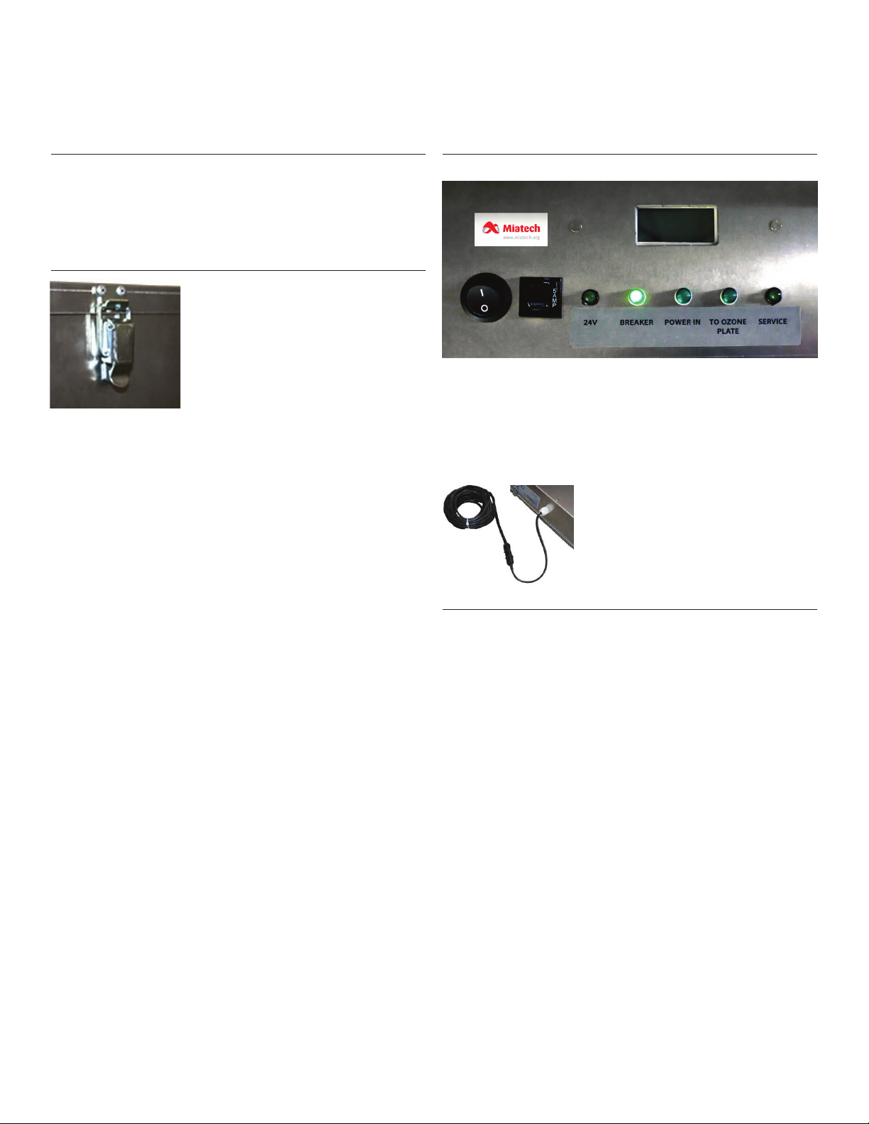
OPERATION
Picture 2
Aer supplying the V power to the system, “Breaker” LED should
be glowing green. This shows that power is to the system and the
circuit breaker is good. Turn on the power switch. Three more LED’s
should come “ON”. These indicate there is power to the transformer,
power to the fan and to the ozone generator plate (a low hum should
be detected aer the unit is plugged in) (see picture ).
Picture 3
In case you want to remove Bio Turbo i
from the truck, please disconnect the
unit’s power cable using quick connector
(see picture ).
: Plus on the power cable is
marked with red.
COUNTDOWN SERVICE TIMER
System is equipped with the Service Timer which is counting down
days to the next maintenance when system is operating. Timer
is set to days and when it gets down below days it starts
beeping and Service LED light on the system will flash, signaling
maintenance is due. Service Timer has to be reset back to days
aer maintenance is completed.
Bio Turbo 100i
Installation Guide
Picture 1
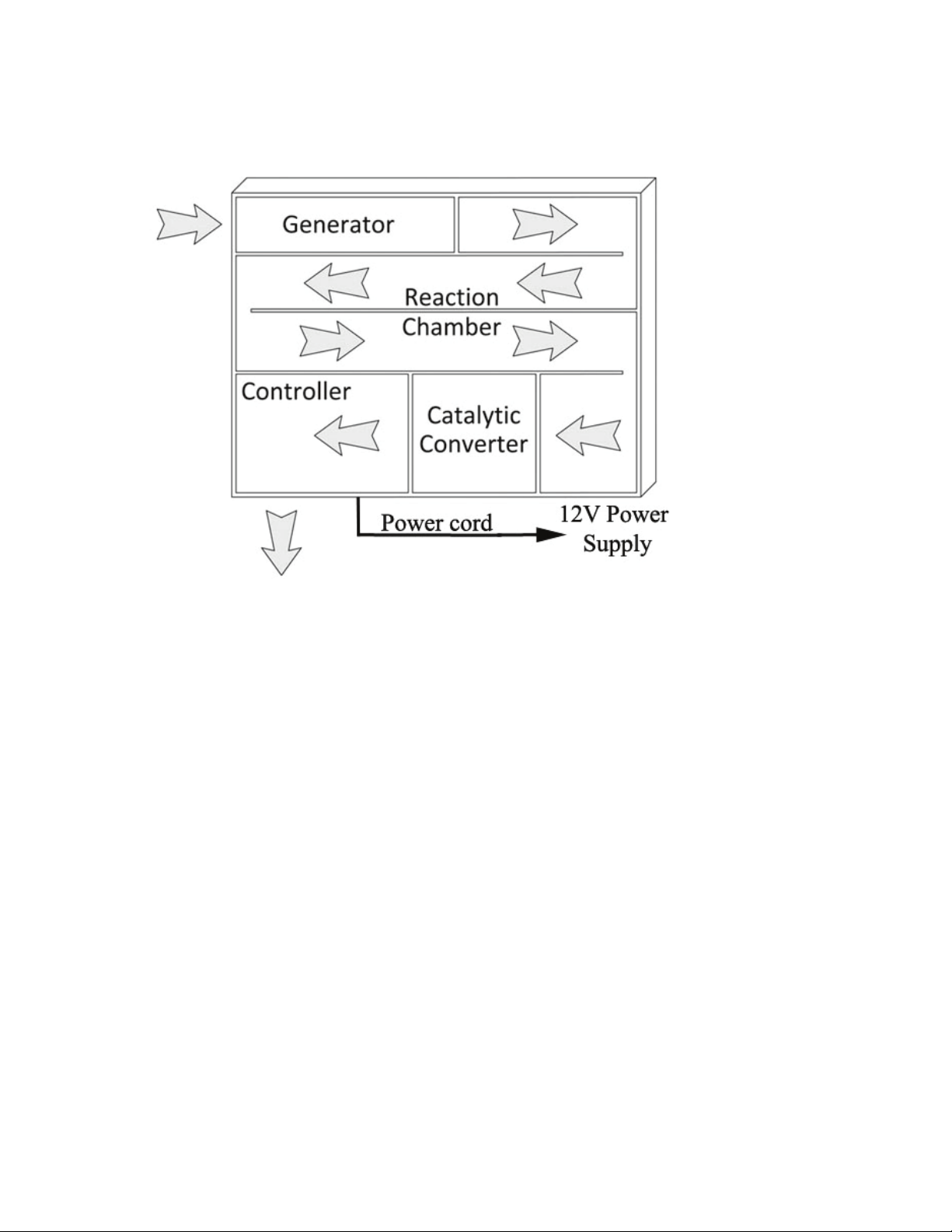
MIATECH TECHNICAL INSTRUCTIONS | BIO TURBO I USER GUIDE LAYOUT DIAGRAM | MAR ,
Bio Turbo 100i
Layout Diagram
BIO TURBO 100i
Toll Free in North America:
1-800-933-6478
www.miatech.org
USA –phone: 1-503-659-5680
Fax: 1-503-659-2204
MAY 2014
THE ADVANTAGE COUNTS
BIO TURBO 100i
LAYOUT DIAGRAM v. 1.1
MIATECH TECHNICAL INSTRUCTIONS | BIO TURBO I USER GUIDE MAINTENANCE GUIDE | MAR ,
Bio Turbo 100i
Maintenance Guide
:
ALWAYS UNPLUG POWER BEFORE SERVICE!
Maintenance Requirements
Annual service requires the replacement of Air Filter
(more oen if environment is very dusty) and the
replacement of the Ozone Generation Plates.
To replace the Air lter and the Ozone Generator Plates:
• Disconnect the unit’s power cable using quick connector.
• Unlatch four snap clips on a holding frame and put
a system on a ground.
• Unscrew the system lid (opposite from holding frame).
• Remove and replace the air lter (#).
• To replace the Generator Plate (#) disconnect the
power cables from plates, release from the holder,
remove and replace with new one.
System is equipped with the Service Timer (#) which
is counting down days to the next maintenance when
system is operating. Timer is set to days and
when it gets down below days it starts beeping
and Service LED light on the controller box will flash,
signaling maintenance is due. Service Timer has to be
reset back to days aer maintenance is completed.
To reset the Service Timer:
• Unscrew two nuts that are holding the timer (from
the inside of the controller box). Remove the timer,
press and hold the reset button until numbers start
flashing. By pressing the same button select
and wait until it denes (numbers will stop flashing).
Place the timer back and secure with nuts.
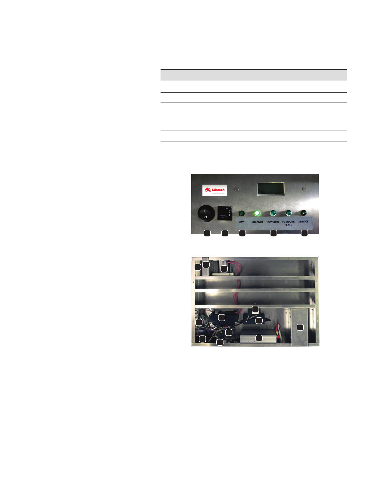
. Power switch (#)
. amp breaker (#)
. V LED (#)
. LEDs V (#), V (#)
. Service V LED (#)
. Air lter (#)
. Lifetime lter pad (#)
. Generator plate (#)
. Door switch (#)
. Ozone transformer (#)
. BT service timer (#)
. Solid state relay (#)
. Fan V DC (#)
. Alarm board for fan (#)
. Power Inverter (#)
. Transformer
V / V (#)
. Catalyst container
Diagnostic LED’s Name Description
“Breaker” (on the Controller Chamber) Power to the Unit
“Power IN” (on the Controller Chamber) Power to the Power Supply
“ V” (on the Controller Chamber) Power to the Fan
“To the Generation Chamber”
(on the Controller Chamber)
Power to the Generation Chamber
“Service” (on the Controller Chamber) When the service is needed
Table of contents
Other Miatech Air Cleaner manuals


