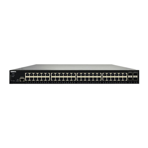
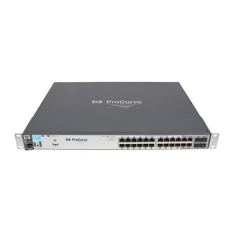
Micas RG-S6520-64CQ Installation and operating manual

Ruijie RG-S6520-64CQ Switch
Hardware Installation and Reference Guide
Document Version: V2.0
Date: November 16, 2023
Copyright © 2023 Ruijie Networks

Copyright
Copyright © 2023 Ruijie Networks
All rights are reserved in this document and this statement.
Without the prior written consent of Ruijie Networks, no organization or individual is permitted to reproduce,
extract, back up, modify, or distribute the content of this document in any manner or form. It is also prohibited to
translate the document into other languages or use any or all parts of it for commercial purposes.
and trademarks are owned by Ruijie Networks.
All other trademarks or registered trademarks mentioned in this document are owned by their respective owners.
Disclaimer
The products, services, or features that you purchase are subject to commercial contracts and terms. It is
possible that some or all of the products, services, or features described in this document may not be available
for purchase or use. Unless agreed upon otherwise in the contract, Ruijie Networks does not provide any explicit
or implicit statements or warranties regarding the content of this document.
The content of this document is subject to constant change due to product version upgrades or other reasons.
Thus, Ruijie Networks reserves the right to modify the content of the document without prior notice or prompt.
This manual serves solely as a user guide. While Ruijie Networks endeavors to ensure the accuracy and
reliability of the content when compiling this manual, it does not guarantee that the content of the manual is free
of errors or omissions. All information contained in this manual does not constitute any explicit or implicit
warranties.

I
Preface
Intended Audience
This document is intended for:
Network engineers
Technical support and servicing engineers
Network administrators
Technical Support
Ruijie Networks website: https://www.ruijienetworks.com/
Online support center: https://ruijienetworks.com/support
Case portal: https://caseportal.ruijienetworks.com
Community: https://community.ruijienetworks.com
Email support: [email protected]
Live chat: https://www.ruijienetworks.com/rita
Conventions
1. Signs
The signs used in this document are described as follows:
Danger
An alert that contains important safety instructions. Before you work on any equipment, be aware of the
hazards involved and be familiar with standard practices in case of accidents..
Warning
An alert that calls attention to important rules and information that if not understood or followed can result in
data loss or equipment damage.
Caution
An alert that calls attention to essential information that if not understood or followed can result in function
failure or performance degradation.
Note
An alert that contains additional or supplementary information that if not understood or followed will not lead to
serious consequences.
Specification
An alert that contains a description of product or version support.

II
2. Notes
The manual provides configuration information, including models, port types, and command line interfaces, for
reference purposes only. In the event of any discrepancy or inconsistency between the manual and the actual
version, the actual version shall take precedence.

I
Contents
Preface.................................................................................................................................................. I
1 Overview ........................................................................................................................................... 1
1.1 About the RG-S6520-64CQ.......................................................................................................1
1.2 Component Modules..................................................................................................................1
1.3 Chassis ......................................................................................................................................1
1.3.1 Appearance....................................................................................................................2
1.3.2 LEDs ..............................................................................................................................4
1.3.3 Ports...............................................................................................................................5
1.3.4 Cooling...........................................................................................................................5
1.3.5 Technical Specifications.................................................................................................6
1.3.6 Asset Tag........................................................................................................................8
1.4 Power Module............................................................................................................................9
1.4.1 RG-PA800I-F................................................................................................................10
1.5 Fan Module..............................................................................................................................12
1.5.1 M1HFAN II-F................................................................................................................12
1.6 Cables......................................................................................................................................13
1.6.1 Console Cable .............................................................................................................13
1.6.2 Ethernet Cable.............................................................................................................14
1.6.3 Power Cord..................................................................................................................14
1.6.4 Grounding Wire............................................................................................................16
1.7 Pluggable Modules..................................................................................................................16
2 Preparing for Installation................................................................................................................. 18
2.1 Safety Guidelines.....................................................................................................................18

II
2.1.1 General Precautions....................................................................................................18
2.1.2 Chassis-Lifting Guidelines...........................................................................................18
2.1.3 Electricity Safety ..........................................................................................................18
2.1.4 Preventing ESD Damage.............................................................................................19
2.1.5 Laser Safety.................................................................................................................19
2.1.6 Storage Guidelines ......................................................................................................19
2.2 Site Requirements...................................................................................................................20
2.2.1 Floor Loading...............................................................................................................20
2.2.2 Airflow...........................................................................................................................20
2.2.3 Space...........................................................................................................................20
2.2.4 Temperature.................................................................................................................20
2.2.5 Humidity.......................................................................................................................20
2.2.6 Cleanliness...................................................................................................................21
2.2.7 System Grounding.......................................................................................................22
2.2.8 Preventing Electromagnetic Interference ....................................................................23
2.2.9 Surge Protection..........................................................................................................23
2.3 Rack-Mounting Guidelines.......................................................................................................23
2.4 Tools ........................................................................................................................................24
2.5 Unpacking the Switch..............................................................................................................25
2.5.1 Verifying the Shipped Content.....................................................................................25
2.5.2 Unpacking the Container.............................................................................................25
3 Installing the Switch ........................................................................................................................ 27
3.1 Installation Procedure..............................................................................................................28
3.2 Installing the Rack....................................................................................................................29

III
3.2.1 Installation Guidelines..................................................................................................29
3.2.2 Procedure.....................................................................................................................29
3.3 Installing the Chassis...............................................................................................................29
3.3.1 Installation Guidelines..................................................................................................29
3.3.2 Mounting the Brackets.................................................................................................30
3.3.3 Mounting the Chassis on the Rack..............................................................................30
3.3.4 Mounting the Chassis on the Workbench....................................................................31
3.4 Installing the Protective Grounding Wire.................................................................................32
3.4.1 Installation Guidelines..................................................................................................32
3.4.2 Procedure.....................................................................................................................32
3.5 Installing and Removing the Fan Module................................................................................33
3.5.1 Installing the Fan Module.............................................................................................33
3.5.2 Removing the Fan Module...........................................................................................34
3.6 Installing and Removing the Power Module............................................................................34
3.6.1 Installing the Power Module.........................................................................................34
3.6.2 Removing the Power Module.......................................................................................36
3.7 Installing the Pluggable Module...............................................................................................37
3.8 Verifying Installation.................................................................................................................37
3.9 Connecting the Power Cord.....................................................................................................38
4 Commissioning................................................................................................................................ 38
4.1 Setting Up the Configuration Environment..............................................................................38
4.2 Powering on the Device...........................................................................................................40
4.2.1 Checklist Before Power-on..........................................................................................40
4.2.2 Power-on......................................................................................................................41

IV
4.2.3 ChecklistAfter Power-on .............................................................................................41
5 Monitoring and Maintenance........................................................................................................... 42
5.1 Monitoring................................................................................................................................42
5.1.1 Monitoring the LEDs....................................................................................................42
5.1.2 Running the CLI Commands.......................................................................................42
5.2 Maintenance ............................................................................................................................42
5.2.1 Replacing the Power Module.......................................................................................42
5.2.2 Replacing the Fan Module...........................................................................................43
5.2.3 Replacing the Lithium Battery......................................................................................43
5.2.4 Replacing the Fuse......................................................................................................43
6 Troubleshooting............................................................................................................................... 44
6.1 Flowchart..................................................................................................................................44
6.2 Common Issues.......................................................................................................................45
6.2.1 Forgetting Login Password..........................................................................................45
6.2.2 AC Power Module Failure............................................................................................45
6.2.3 Fan Module Not Rotating.............................................................................................45
6.2.4 No Output on the Console...........................................................................................45
6.2.5 Garbled Output on the Console...................................................................................45
6.2.6 Optical Port Linkdown..................................................................................................46
7 Appendix.......................................................................................................................................... 47
7.1 Labeling Process.....................................................................................................................47
7.1.1 Hand Writing on Labels................................................................................................47
7.1.2 Pasting Labels .............................................................................................................47
7.1.3 Label Contents.............................................................................................................48

V
7.2 Connectors and Media.............................................................................................................49
7.2.1 100BASE-TX/10BASE-T Port......................................................................................49
7.2.2 1000BASE-T Port ........................................................................................................49
7.3 Surge Protection......................................................................................................................51
7.3.1 Installing an AC PowerArrester...................................................................................51
7.3.2 Installing an Ethernet Port Arrester..............................................................................52
7.4 Site Selection...........................................................................................................................54
7.5 Recommended Cabling...........................................................................................................54

Hardware Installation and Reference Guide Overview
1
1 Overview
1.1 About the RG-S6520-64CQ
The RG-S6520-64CQ switch is a next-generation 40GE/100EG Ethernet switch featuring high-performance,
high-density, and low-latency launched by Ruijie Networks for data center and high-end campus networks. The
RG-S6520-64CQ switch delivers high-density 40GE/100GE access, Top-of-Rack (ToR) uplink convergence, and
diverse data center features. It can be used with Ruijie’s RG-N18000-X and RG-S6920-4C switches for a high-
performance and high-reliability data center network.
Table 1-1 RG-S6520-64CQ Overview
Chassis
100GE DSFP
Ports
Expansion
Slots
Power
Redundancy
Fan Redundancy
RG-S6520-64CQ
64
N/A
1 + 1
2 + 1
Note
The product images involved in this manual are for indicative purpose only. The appearance is subject to the
actual equipment.
1.2 Component Modules
The RG-S6520-64CQ adopts the modular design. Compliant with industry standards, the design differentiates
modules and integrates module interfaces to ensure an integrated system with independent function modules.
Table 1-2 Component Modules
Chassis
Power Module
Fan Module
RG-S6520-64CQ
RG-PA800I-F
M6520-FAN-F
Caution
Different power modules are interchangeable. That is, the switch allows concurrent AC and High-voltage DC
(HVDC) input. For example, input 1 uses mains electricity (AC power) and input 2 use Uninterrupted Power
Supply (UPS) HVDC power.
1.3 Chassis
The RG-S6520-64CQhardware system consists of a chassis, a power supply system, and a cooling system.
Power supply system: provides two power module slots and supports 1 + 1 power redundancy.

Hardware Installation and Reference Guide Overview
2
Cooling system: provides three fan module slots and supports 2 + 1 fan redundancy.
Note
The management software is already pre-installed in the system.
1.3.1 Appearance
1. Appearance
Figure 1-1 Front View of the RG-S6520-64CQ
Figure 1-2 Rear View of the RG-S6520-64CQ

Hardware Installation and Reference Guide Overview
3
2. Structure
Figure 1-3 Front Panel Structure
1
2 4
3 5
6
7
Table 1-3 Front Panel Components
No.
Component
1
System status LED
2
Locator LED
3
Console port
4
Management port
5
USB port
6
QSFP28 port
7
QSFP28 port LED
Figure 1-4 Rear Panel Structure
Table 1-4 Rear Panel Components
No.
Component
1
Power module slot

Hardware Installation and Reference Guide Overview
4
No.
Component
2
Fan module slot
3
Asset tag
4
Fan module status LED
5
Grounding stud
1.3.2 LEDs
Table 1-5 LEDs
Silkscreen Label
LED
Description
SYS
Status LED
Solid green: The system is operating normally.
Blinking green: The system is starting up.
Solid red:
○The system (including all modules) is not functioning
properly.
○Less than three fan modules are installed.
○The temperature exceeds the limit and the switching service
resets.
Off: The system is not receiving power or not operating even
after receiving power.
ID
Locator LED
Solid blue: Locating is enabled.
Off: Locating is disabled (default).
1F to 48F
SFP28 port LED
Solid green: The port has made a successful link.
Blinking green: The port is sending and receiving traffic.
Off: No link is detected for the port.
LINK/ACT
Management
port LED
LINK
○Solid yellow: The port has made a successful 10/100 Mbps.
○Solid green: The port has made a successful 1000 Mbps.
○Off: No link is detected for the port.
ACT
○Blinking yellow: The port is sending and receiving traffic at
10/100 Mbps.
○Blinking green: The port is sending and receiving traffic at
1000 Mbps.
○Off: The port is not sending or receiving traffic.

Hardware Installation and Reference Guide Overview
5
1.3.3 Ports
Table 1-6 Ports
Port
Connector Type
Description
Accessory
100GE QSFP28port
Subject to the optical
module
The 100GE QSFP28 port is
backward compatible with 40GE
and can be split into four 10GE or
25GE ports for uplink data
transmission.
Standards compliance:
IEEE802.3ba
Working mode: Full-duplex
Optical attributes: Subject to
the module or cable
100GE optical module
40GE optical module
AOC
Management port
RJ45
The management port is used to
set up the local or remote
configuration environment.
Standards compliance:
IEEE802.3ab
Working mode: 10/100/1000
Mbps with auto-negotiation
and full-duplex
CAT5 or higher cable
USB port
USB
The USB port is connected with a
USB flash drive for configuration
backup and firmware upgrade.
USB 2.0
FAT32 file format
USB 2.0 flash drive
Console port
RJ45
The console port is connected to a
console for local configuration.
Standards compliance: RS-
232
Working mode: Duplex
Universal Asynchronous
Receiver/Transmitter (UART)
Baud rate:
○Range: 9,600 bits/s to
115,200 bits/s
○Default value: 9,600 bits/s
Console cable
1.3.4 Cooling
The RG-S6520-64CQ adopts the front-to-rear airflow. Air flows in through the ports and out through the power
module, as shown in Figure 1-5.
Caution
Maintain a minimum clearance of 200 mm (7.87 in.) around the equipment for air circulation.

Hardware Installation and Reference Guide Overview
6
At least five fan modules are required. If any slot is unoccupied, install a filler panel to enable proper
airflow and to keep dust out of the chassis.
Dust the equipment every three months to avoid blocking the ventilation openings on the housing.
Figure 1-5 Front-to-Rear Airflow
1.3.5 Technical Specifications
Table 1-7 Technical Specifications
Class
Item
Specification
Technical
indicators
CPU
1.5 GHz quad-core
Memory
4 GB, DDR4 (compatible with 8 GB)
Flash memory
NOR flash: 8 MB (for BootROM)
NAND Flash: 8 GB
Physical
characteristics
Dimensions
(W x D x H)
Without packing materials: 442 mm x 450 mm x 88.1
mm (17.40 in. x 17.72 in. x 3.47 in., 2 RU)
With packing materials: 665 mm x 715 mm x 262 mm
(26.18 in. x 28.15 in. x 10.31 in.)
Weight
Chassis and modules (three fan modules and two power
modules) without packing materials: 20 kg (44.09 lbs.)
Structure
Integrated chassis without expansion module slots
Two power module slots
Three fan module slots
Ports
Service port
64 x 100GE QSFP28 ports, backward compatible with 40GE,
each port splittable into four 10GE or 25GE ports
Console port
1 x RJ45 port
USB port
1 x USB 2.0 port

Hardware Installation and Reference Guide Overview
7
Class
Item
Specification
Management port
1 x Gigabit RJ45 port supporting backward compatibility
Environment
Altitude
Operating altitude: 0–5,000 m (0–16,404.20 ft.)
Storage altitude: 0–5,000 m (0–16,404.20 ft.)
Temperature
Operating temperature: 0°C to 45°C (32°F to 104°F) at
an altitude in the range of 0–2,000 m (0–5,905.51 ft.)
Note
At an altitude in the range of 2,000–5,000 m
(5,905.51–16,404.20 ft.), every time the altitude
increases by 200 m (656.17 ft.), the maximum
temperature decreases by 1°C (1.8°F).
Storage temperature: –40°C to +70°C (–40°F to
+158°F)
Humidity
Operating humidly: 10% RH to 90% RH (non-
condensing)
Storage humidity: 5% RH to 95% RH (non-condensing)
Noise
Sound pressure level at 27°C (80.6°F): < 78 dB
Surge protection
AC power protection
Common mode: 2 kV
Differential mode: 1 kV
Power supply
Power supply
mode
AC
HVDC
Power connector
C14 three-pin connector
Power consumption
Max: 600 W
Typical: 410 W
Static: 222 W
Voltage
AC: 100 V AC to 240 V AC, 50 Hz to 60 Hz
HVDC: 180 V DC to 310 V DC
AC input
RG-PA800I-F:
Rated voltage: 110 V AC or 220 V AC
Rated voltage range: 100 V AC to 120 V AC or 200 V AC
to 240 V AC (50 Hz to 60 Hz)
Max. voltage range: 90 V AC to 264 V AC (47 Hz to 63
Hz)
Rated current range: 5 A to 10 A
DC input
RG-PA800I-F:
HVDC range: 180 V DC to 310 V DC
Rated voltage: 240 V DC
Rated current: 5 A

Hardware Installation and Reference Guide Overview
8
Class
Item
Specification
Max. output power
consumption
RG-PA800I-F: 800 W
Airflow direction
RG-PA800I-F: Front-to-rear airflow (air exhaust on power
module panel)
Cooling
Cooling mode
Fan cooling
Fan type
Swappable fan
Reliability
Mean Time to Recovery
(MTTR)
0.5 hours
Power redundancy
1 + 1
Fan redundancy
2 + 1
Hot swapping
Hot swappable power and fan modules
Certification
EMC
GB/T 9254.1
Safety standard
GB 4943.1
Environment protection
Environment protection regulation
Warning
Operation of this equipment in a residential environment could cause radio interference.
This equipment is not suitable for use in locations where children are likely to be present.
This equipment should be installed in the equipment room. Only a skilled person should be allowed to
install, replace, or service this equipment. Do not open the enclosure when the equipment is running. Cut
off the power supply before opening the enclosure in case of an electric shock.
1.3.6 Asset Tag
The asset tag is in the lower left corner of the front panel. The tag can be pulled out of the panel. You can add
your own asset tracking label without interfering with the intended air flow.
Figure 1-6 Asset Tag

Hardware Installation and Reference Guide Overview
9
1.4 Power Module
The smart power module for the RG-S6520-64CQ supports power consumption management and hot swapping.
It can obtain the output power, output current, and operating temperature in real time.
Caution
To improve system stability and availability, you are advised to configure 1 + 1 power redundancy. The
chassis configured with power redundancy works in current-sharing mode.
At least one power module is required. If any slot is unoccupied, install a filler panel to enable proper
airflow and to keep dust out of the chassis.
Unplug the power cord before installing or removing the power module.

Hardware Installation and Reference Guide Overview
10
1.4.1 RG-PA800I-F
1. Appearance
Figure 1-7 Appearance
Figure 1-8 Structure
Table 1-8 Components
No.
Component
Description
1
Fan
Front-to-rear airflow
2
Handle
Handle of the power module
3
Power connector
Three-pin connector
4
Latch
Latch of the power module
5
LED
Power status LED

Hardware Installation and Reference Guide Overview
11
2. LED
Table 1-9 LED
Silkscreen
Label
LED
Description
N/A
Power status
LED
Solid green: The power module is outputting power normally.
Blinking green at 1 Hz:
○The power module is in PS OFF state with only 12 V standby output.
○The power module is in the cold standby status and not outputting
power.
Solid red:
○The power module is not functioning properly (overcurrent,
overvoltage, or fan failure).
○The power module in redundancy mode is removed.
Blinking red at 1 Hz: The power module is operating but with alarms,
such as high power, high current, high temperature, and low fan
rotation speed.
Off: The power module is not receiving power or not operating even
after receiving power.
3. Technical Specifications
Table 1-10 Technical Specifications
Item
Specification
Dimensions (W x D x H)
Without packing materials: 73.5 mm x 185 mm x 40 mm (2.89 in. x
7.28 in. x 1.57 in.)
With packing materials: 462 mm x 195 mm x 232 mm (18.19 in. x
7.68 in. x 9.13 in.)
Weight
Without packing materials: 0.9 kg (1.98 lbs.)
With packing materials: 1.5 kg (3.31 lbs.)
Power connector
C14 connector for connection with AC or HVDC power cord
Rated input voltage range
AC: 100 V AC to 240 V AC, 50 Hz to 60 Hz
HVDC: 240 V DC
Max. input voltage range
AC: 90 V AC to 264 V AC, 47 Hz to 63 Hz
HVDC: 180 V DC to 310 V DC
Max. input current range
AC: 5 A to 10 A (100 V AC to 240 V AC)
HVDC: 5 A (180 V DC to 310 V DC)
Rated output voltage
12 V DC
Rated output current
65 A
Rated output power consumption
800 W
Hot swapping
Supported
Cooling
Front-to-rear airflow
Table of contents
Other Micas Switch manuals
Micas
Micas M2-W6510-32C Installation and operating manual

Micas
Micas M2-W6510-48GT4V Installation and operating manual

Micas
Micas M2-S6920-4S Installation and operating manual
Micas
Micas M2-W6510-48V8C Installation and operating manual
Micas
Micas RA-BM2-W6510-48V8C Installation and operating manual

Micas
Micas M2-W6930-64QC Installation and operating manual
Micas
Micas M2-S6510-48V8C Installation and operating manual
Micas
Micas M2-S6930-64QC Installation and operating manual

Micas
Micas M2-W6920-4S Installation and operating manual
Micas
Micas M2-S6510-32C Installation and operating manual
