Michaelis Maschinenbau KM 20 T User manual
Edition 03/2016
Operating Instructions /
Spare Part List
Michaelis
Weed Control Maschine
KM 20 T/TS – TO/TSO
Fabr.-Nr.: ……….-……….
MICHAELIS
masc hinenbau
Huxfelder Straße 8 Telefon (0049) 4208 8294-0
D-28879 Grasberg Telefax (0049) 4208 506
www.michaelis-maschinenbau.de info@michaelis-maschinenbau.de
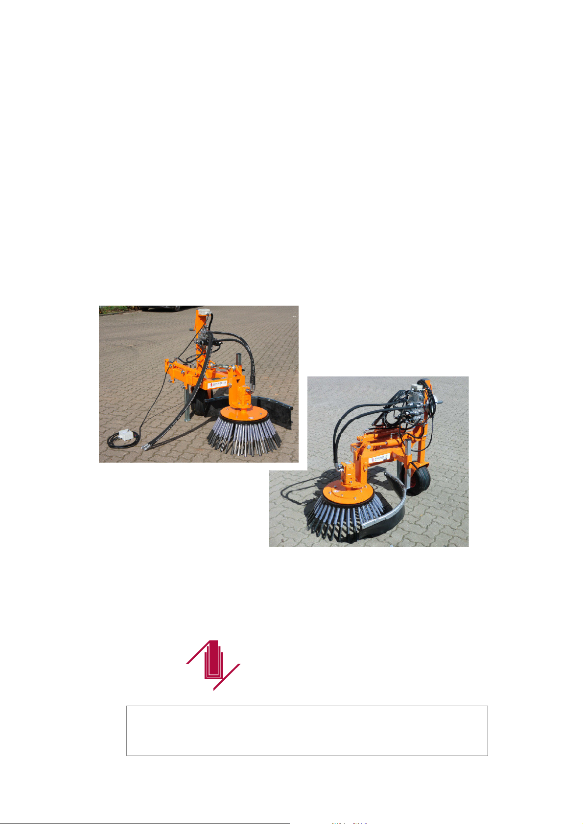
KM 20 T / TS
with hydraulic cylinder
KM 20 TO / TSO
with top link

- 2 -
MICHAELIS
masc hinenbau
1. Contents
1. Contents page 2
2. Technical data page 3
3. Operating Instructions page 4
4. General description page 5
4.1 Field of Application page 5
4.2 vehicle to be used page 5
4.3 Technical requirements page 5
5. Attachment page 6
6. Start up page 6
6.1 Typ KM 20 T/TS with hydraulic cylinder
the brush head tilt
page 6
6.2 Typ KM 20 TO/TSO with top link
the brush head tilt
page 7
7. Operation page 8
7.1 KM 20 T/TS –
Function mini control panel with hydraulic cylinder page 8
7.2 KM 20 TO/TSO –
Function mini control panel with top link page 8
8. Work deployment page 9
8.1 Tip to the period of implementation page 10
9. Brush types page 10
10. Brush change page 11
11.1 Brush change - Flat steel brush page 11
11.2 Brush change - Quick-change system page 12
11. Impact protection element page 13
12. Maintenance page 13
13. Support wheel page 13
14. Safety note page 14
Spare Part List KM 20 TO/TSO + T/TS
Electrical and hydraulic system with hydraulic cylinder
Electrical and hydraulic system with top link
in the appendix (Depending equipment)
Content errors reserved

- 3 -
MICHAELIS
masc hinenbau
2. Technical Data
Designation: Front device for weed removal and cleaning
__________________________________________________________________________
Typ KM 20 T / TO:
Front device for weed removal
With hydraulic sideshift
Weight KM 20 T/TO: 130 kg
Basic dimensions ca. (LxBxH): approx. 1,35 x 1,00 x 1,13 metres
Oil flow minimum: 25-30 l/min (Motor OMS 125) standard,
possibly amended by individual adaptation
to the carrier vehicle
Working pressure: 160 bar
Lateral adjustment of the brush: Hydraulic
Stroke of the side shift: 385 mm
Side reach from center: 1165 mm
Optionally with top link or cylinder
__________________________________________________________________________
Typ KM 20 TS / TSO:
Front device for weed removal
with hydraulic sideshift
Weight KM 20 TS/TSO 215 kg
Basic dimensions ca. (LxBxH): 1,70 x 1,07 x 1,15 m
Oil flow minimum: 35 l/min (Motor OMS 200) standard,
possibly amended by individual adaptation
to the carrier vehicle
Working pressure: 160 bar
Lateral adjustment of the brush: Hydraulic
Stroke of the side shift: 500 mm
Side reach from center: 1380 mm
Optionally with top link or cylinder
__________________________________________________________________________
Weed brush diameter Ø: standard flat steel brush KM20-5
On request twist knot brush with quick-change
system for individual removal twist knot KM20-8
According to directive: 2006/42/EG
Manufacturer: Michaelis Maschinenbau GmbH,
D-28879 Grasberg

- 4 -
MICHAELIS
masc hinenbau
3. Operating Instructions
We are pleased that you have decided to purchase this machine. It has been made
using state-of-the-art technology and quality workmanship. To ensure that the
machine has a long service life some basic duties are necessary.
Description of safety notes
Safety notes are marked by a pictogram or a
signal word. The signal word describes the
severity of the impending risk.
DANGER Imminent danger to life and health of persons
(severe or fatal injuries).
WARNUNG Possible danger to life and health of persons
(severe or fatal injuries).
CAUTION Possible dangerous situation (minor injuries
or material damage).
NOTE Tips for use and other particular useful
information.
IMPORTANT Obligation of a particular behavior or an action
for the safe handling of the machine.
REFERENCE
Gives a cross-reference to a particular
document or an action for the safe handling of
the machine.

- 5 -
MICHAELIS
masc hinenbau
4. General description
The KM 20 T / KM 20 TS is a front-mounted attachment with special weeds brushes for easy
and effective, eliminating mechanical fugues and moss paved surfaces, paths, places and
roadsides. Ideal for work in the edge region.
It is easily controlled from the driver's cab, optimal overview is given and can be adapted to
different vehicle widths.
Drive over existing on the tractor or other vehicle carrier oil circuit.
A simple and independent installation by hydraulically driven Brush-plate and side
adjustment by hydraulic cylinders.
Brush head tilt as standard mechanical.
Please read the instructions carefully to familiarize yourself with the operation and
maintenance of the appliance!
The following points should always be observed:
4.1 Field of application
The primary function of the machine is to remove weed of paved areas from ways and
roadsides. In addition it is suitable for general cleaning (e.g. kerbs), but it is not for interior
use or for terraces and narrow paths.
4.2 Vehicle to be used
Most suitable are carrier vehicles with an automatic hydrostatic system for infinitely
adjustable back and forth driving at variable speed. The vehicle must have an excavation
device or floating position.
4.3 Technical requirements:
- When a tractor municipal traktors triangle should be available tob e able to
accommodate devices triangles (To appoint frame size in advance)
or an additional mounting plate
- Oil flow minimum:
KM20T= 20l/min (OMS125) or KM20TS=35l/min (OMS200)
- Power supply 12 V
- With at least one double-acting hydraulic control circuit
REFERENCE
The specifications of the documentation have to
be attended concurrently.
IMPORTANT
The technical requirements for operation have
to be met.
- 6 -
MICHAELIS
masc hinenbau
5. Attachement
A professional attachment has to be carried out by qualified staff.
Pay attention to the attachment specifications of the carrier vehicle manufacturer and the
road traffic act concerning: track protruding parts / distance steering wheel center to front
edge of attachment.
When attaching the machine it has to be further taken into account that all adjustment
options can be used in every operation position (clearance).
The fulcrums have to be well greased and must move smoothly.
6. Start up
The Weed machine needed to operate a hydraulic control circuit.
The drive of the machine is achieved on the hydraulic system of the carrier vehicle.
The hydraulic hoses are connected with the terminals on the carrier vehicle.
The working pressure is 160 bar.
6.1 Typ KM 20 T / TS (with hydraulic cylinder the brush head tilt)
With the help of change-over valves of the main frame during the brushing operation can on
or off (-2S1) are driven and the "tendency of the brush head" (-2S2) be set.
To select serves a mini control panel see 7.1.
The control desk is equipped with 1 cable connection.
Plug –X01 is designated for the connection on the on-board power supply from carrier vehicle.
The telescoping of the main frame with brush and the tilting of the brush head is provided
by a hydraulic cylinders.
The oil flow is required at KM20T mind.: 25-30 l/min. (OMS-125)
KM20TS mind.: 35l/min. (OMS-200)
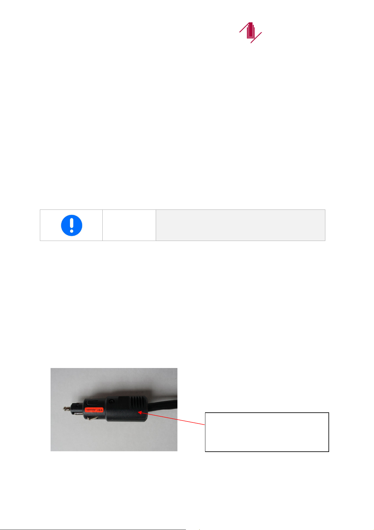
WICHTIG Tight fit of the connector and hydraulic hoses to
look out for
Plug – X01 Connection to the
on-board power
supply
Picture
1

- 7 -
MICHAELIS
masc hinenbau
6.2 Typ KM 20 TO / TSO (with top link the brush head tilt)
Using the integrated diverter valve can be either the brush driven or telescoped laterally.
To switch the functions "the brush operating" or "side adjustment" is a Mini control panel,
see Section 7.2
The control desk is equipped with 2 cable connection.
Plug –X01 is designated for the connection on the on-board power supply from carrier vehicle.
Plug –X02 is connected to the connection box to the equipment.
The telescoping of the main frame with the brush by means of hydraulic cylinders.
The oil flow is required at KM20TO mind.: 25-30 l/min. (OMS-125)
KM20TSO mind.: 35l/min. (OMS-200)
The brush head tilt is done by manual adjustment of the threaded top link
see page 9 - Picture 6
DANGER
Before starting work with the front-mounted
machine attention hast o be paid that no
persons are within the imminent work area.
IMPORTANT
The clearance of all moving parts hast o be
ensured
Connection box on the
unit for plug X02
Picture 2
Picture
3
Plug –X01 connection to 12V
power socket
- 8 -
MICHAELIS
masc hinenbau
7. Operation
During operation the machine has to be driven solely in floating position for better adaption to
ground unevenness and in order to avoid damage to the machine itself and to prevent high
brush wear. An additional contact pressure has to be absolutely avoided.
The depth wheel has to been adapted according to the brush position.
The adaption of the machine has to take place through the implement triangle or the three-
point hitch. The hydraulic hoses have to be firmly mounted. The clearance of all movable
parts has to be ensured.
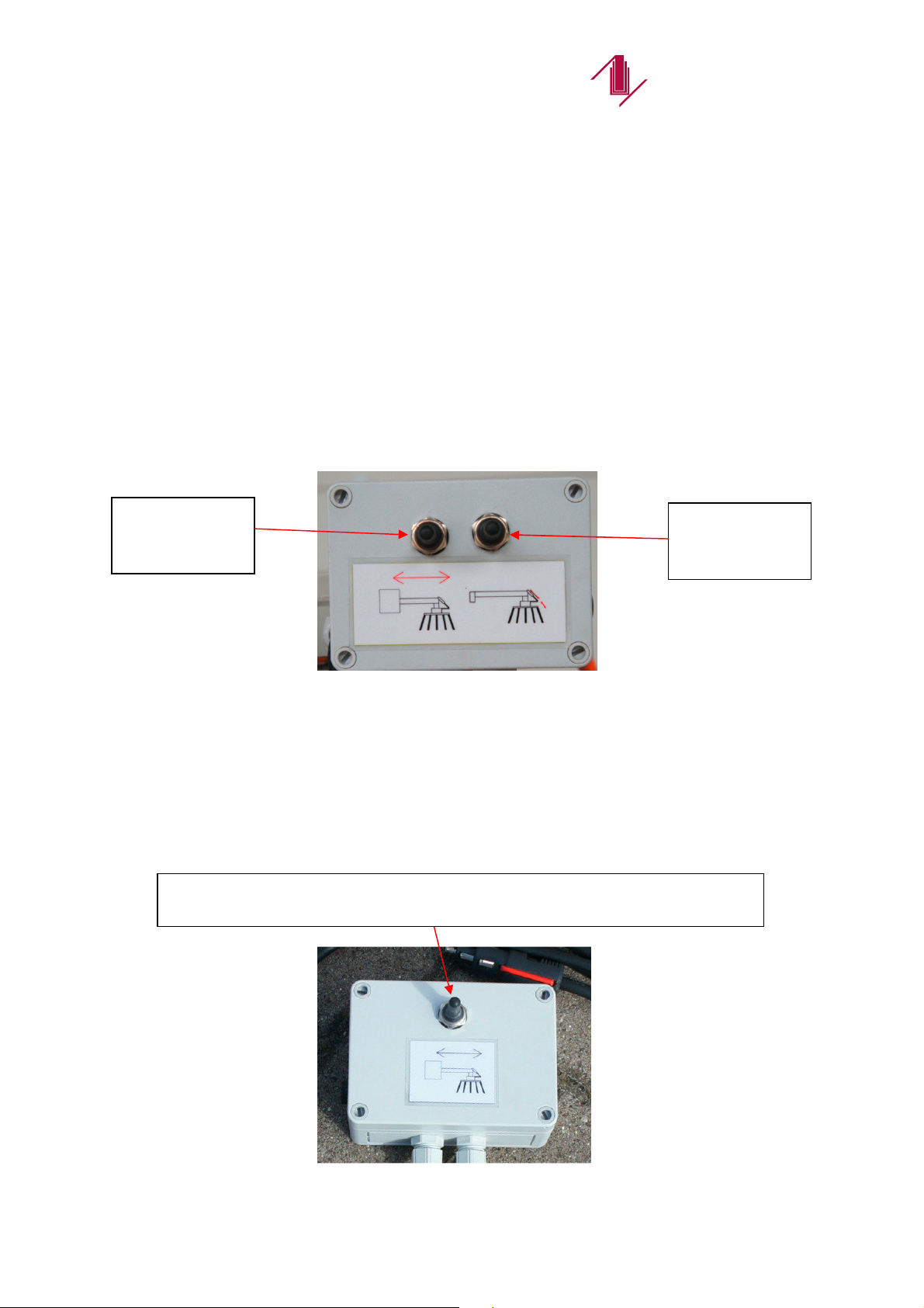
7.1 KM 20 T / TS - Function mini-control panel with hydraulic cylinder
The control desk has 2 functions. On the one hand the telescoping of the main frame
with brush (2S1, left-right) and the other hands tilting the brush head (2S2: up-down).
All functions are applicable during the brush is working.
7.2 KM 20 TO / TSO - Function mini-control panel with top link
With the control panel you have the option by tilting back of the toggle switch
the function of the brush to choose operating or side adjustment.
Both functions are activated with the control valve of the carrier vehicle.
.
-2S1:
telescoping
-2S2:
tilting the
Brush head
Picture 4
Mini control panel with hydraulic cylinder
toggle switch left setting: retract /
extend side adjustment
toggle switch setting right: Brush operation
Picture 5
Mini control panel with top link
- 9 -
MICHAELIS
masc hinenbau
8. Work deployment
Depending on the intensity of dirt on the surface to be cleaned and its material the
performance and the necessary approach differ very much and it can only be learnt by
practice and experience.
To get an optimal cleaning result while treating slick or smoothed surfaces or for removing
heavy earth and snow the brush disc should be inclined accordingly.
For weed cleaning an inclined position has always to be selected.
This is the only way for intensive cleaning.
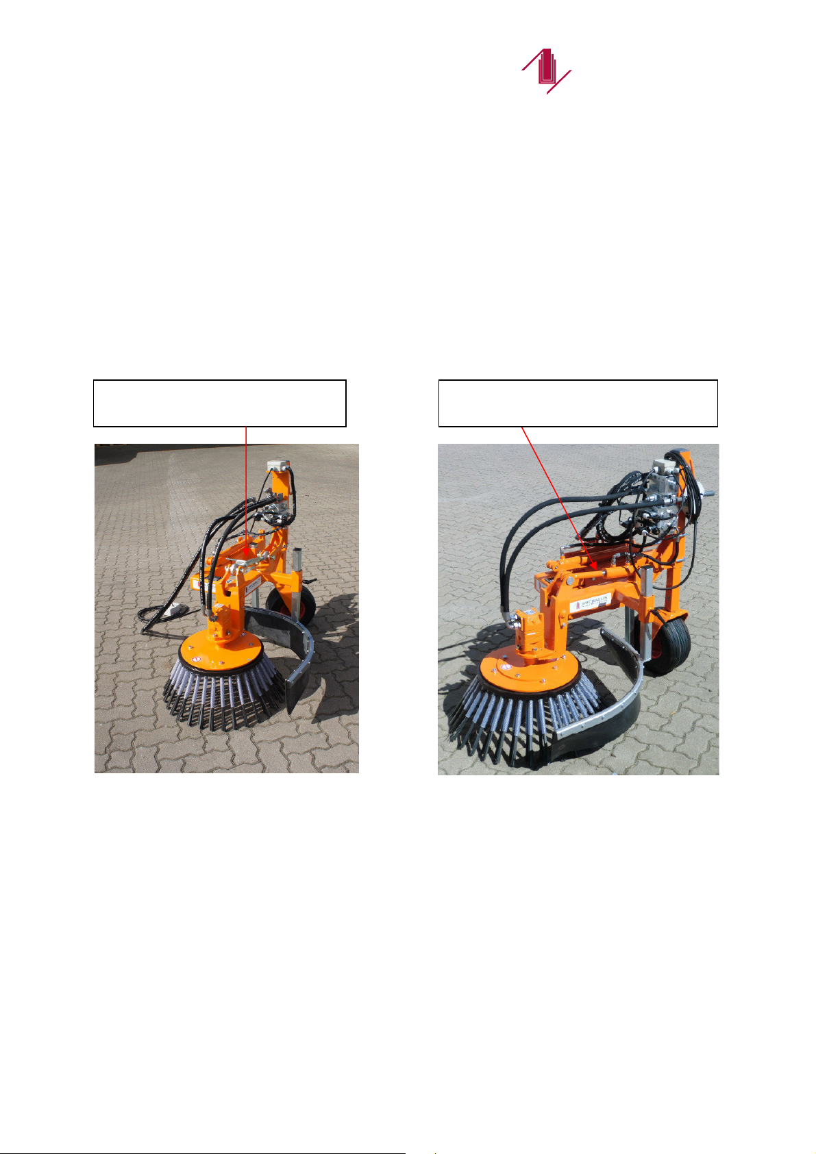
Setup: very steep - for cobblestone
Slightly flatter - rectangular or interlocking stone
Adjustment brush head tilt
mechanically
Picture 6
With top link
The tilt angle of the brush
is manually on preassembled
Top link set to.
Picture 7
with hydraulic cylinder
The tilt angle of the brush
is the hydraulic cylinder
set to.
Adjustment brush head tilt
hydraulic

- 10 -
MICHAELIS
masc hinenbau
8.1 Tip to the period of implementation
The mechanical weed removal should be executed primarily before a new growing season,
hence on frost-free grounds between October and March. Also wet ground conditions are
well suited for getting optimal work results. If using the machine in dry periods or on a
particular hot day the area should be watered.
9. Brush types
HINWEIS The manufacturer offers different types of
brushes.
The appliance is equipped with the universal flat steel brush KM20
NOTE Consider the weather conditions before starting
up see Section 8.1
Flat steel
brush KM 20
-
5:
For weed and moss
Especially intensive cleaning of joints
Only to be used on small tractors
SWS
-
Brush Quick
-
change system KM 20
-
8:
For surface cleaning with a high proportion of material
Not for cleaning joints
Picture
8
Pictu
re
9
- 11 -
MICHAELIS
masc hinenbau
10. Brush change
DANGER
Be sure to turn all aggregates before starting
work on the brush and solve power plug from
the unit.
After changing a brush for tight fit of the screws must be checked and these may need to be
tightened after one working hour.
IMPORTANT
Check all fittings and locks are secure.
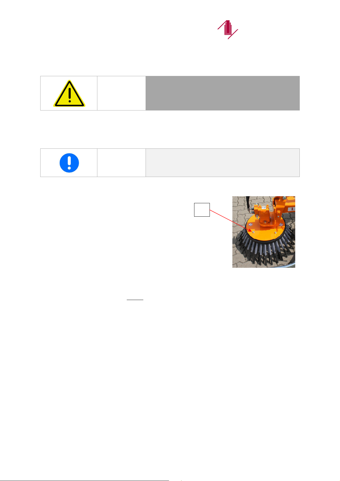
10.1 brush change – Flat steel brush
The different brushes at the brush plate
Attached and can be solved simply by
the 4 screws and remove the brush insert
changing.
In the flat steel brush (KM20-5) are for fixing rubber bushings
mounted at the top.
These need to be cut from the inside along at 3-5 cm after a brush wear of about 5 cm to the
worn area with a knife (ideally utility knife), so that they retain their elasticity.
4x
Picture 10

- 12 -
MICHAELIS
masc hinenbau
10.2 Brush change
Quick-change system – KM20-8 (available on request)
With the enclosed wrench it is easy to replace the single tufts of the twist knot brush KM20-8.
Put the wrench with the open-end under the sprung hexagon bolt (1) and lever towards the
middle of the brush. Thereby you loosen the locking and remove the tuft. Put the
replacement tuft in the square opening all the way to the stop and let the bolt lock in the
provided hole (2) by releasing the wrench.
Check the correct seat and fixture of the tufts after the replacement.
IMPORTANT
Make no joints cleaning with the Quick-change
system
Flatsteel brush only to be used on small tractors
1
2
Picture 11
Picture
13
Picture
12

- 13 -
MICHAELIS
masc hinenbau
11. Impact protection element
It has a lot of adjustment options and has to be set according to the different demands.
Depending on application possible additional protective measures have to be taken:
Barrier posts with plastic covering
Should be secured by covering it with a protection tube.
Base course
Should possibly be protected by putting a steel or wooden plate in front of it.
Traffic island
Should be additionally secured by a transportable large cover where necessary.
12. Maintenance
KM20T/TS und KM20TO/TSO
The 2 grease nipples on the wheel all
10 operating hours Lubricate.
Check bolts for tightness.
13. Support wheel
On different carrier vehicles the depth wheel has to be used in floating position as well in
order to ensure an exact guidance of the broom.
WARNING
When working with no or not properly adjusted
impact protection damage to property or
personal injury can arise!
CAUTION Mind a safety distance.
grease nipples
Picture
14

- 14 -
MICHAELIS
masc hinenbau
14. Safety notes
Before using the machine for the first time the operator has to make himself intensive familiar
with the machine and has to read the operation manual carefully.
The respective guidelines of the responsible employers’ liability insurance association have
to be observed.
The respective specifications for installation of the carrier vehicles such as payloads, number
of revolutions and clearance have to be strictly observed.
Also the attachment guidelines of the road traffic act for lateral protrusion and distance
steering wheel centre to front edge of the attachment have be strictly observed.
The machine may only be use for its intended purpose on open spaces without obstacles for
cleaning work, not in enclosed rooms, on steps and terraces or for other purposes.
The machine may only used with all protective equipment, whose functions and intactness
has to be continuously ensured, properly putted up.
The areas to be cleaned have to be relieved of foreign objects such as stones, because
these can be ejected, before starting work.
The operator is liable to third parties. Other persons have to be send out of the working area.
IMPORTANT
Every user must have undergone a detailed
instruction about operating the machine.

Edition 03/2016
Spare Part List
Michaelis
Weed Control Maschine
KM 20 T/TS – TO/TSO
Fabr.-Nr.: ……….-……….
MICHAELIS
masc hinenbau
Huxfelder Straße 8 Telefon (0049) 4208 8294-0
D-28879 Grasberg Telefax (0049) 4208 506
www.michaelis-maschinenbau.de info@michaelis-maschinenbau.de
KM 20 T / TS
with hydraulic cylinder
KM 20 TO / TSO
with top link
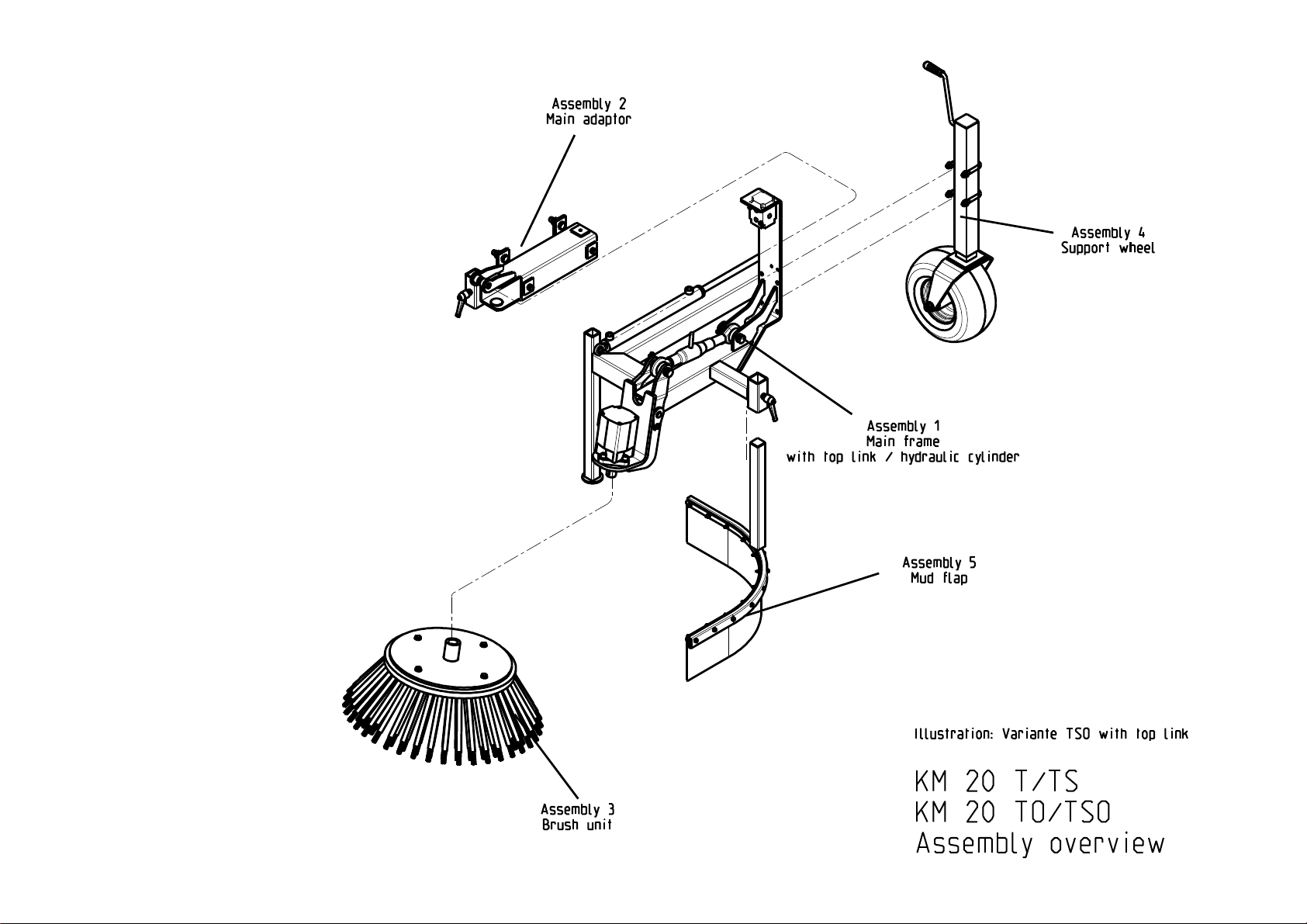

KM 20 T / TS
Assembly 1 Main frame with hydraulic cylinder
Pos.
St.
Description DIN
KM 20 T KM 20 TS
Order
-
Nr.
Order
-
Nr.
1 1 Extension cylinder 32x20x350 - SH-3220350 -
Extension cylinder 40x25x500 - SH-4025500
2 4 Socket head screw M10x20 DIN 912 S 006-067 S 006-067
3 1 Adaptor extension cylinder - 20T0500 -
- KM20TS_5_00
4 1 HPH Block 11106-MICH 010-00
11106-MICH 010-00 11106-MICH 010-00
5.1 2 Socket head screw M10x80 DIN 912 S 006-288 S 006-288
5.2 2 Schnorr Disc A10 DIN 6796 S 006-286 S 006-286
6.1 1 Hexagon bolt M8x140 DIN 931 00538140 00538140
6.2 1 Washer A8 DIN 125 S 006-106 S 006-106
7.1 2 Slotted straight pin 6x40 DIN 1481 S 006-456 S 006-456
7.2 2 Washer ø20 DIN 125 S 006-065 S 006-065
8.1 1 Step bolt short
KM20T_06_05_00 KM20T_06_05_00
8.2 1 Step bolt long
KM20T_06_03_00
KM20T_06_03_00
9 1 Hydraulic cylinder 35x25x50 STS4025500 STS4025500
10 1 Adjustable clamping lever - 40-5560 40-5560
11 1 Pin NL 120 ø25 - BOL_25123 -
Pin NL 143 ø25 -
BOLGEW_25143
12 1 Washer A8 DIN 125 S 006-106 S 006-106
13 1 Hexagon bolt M8x20 DIN 933 S 006-103 S 006-103
14 1 Motor bracket - 20T0301 -
- KM20TS_3_01
15 1 Washer A24 DIN 125 S 006-066 S 006-066
16 1 Castle nut M24 DIN 937 S 006-126 S 006-126
17 1 Slotted straight pin 5x36 DIN 1481 S 006-306 S 006-306
18 1 Hydraulicmotor
Sauer Danfoss OMS 125 *
- 151 F0 502 -
Hydraulicmotor
Sauer Danfoss OMS 200 *
- 151 F0 504
19 4 Schnorr Disc A12 DIN 6796 S 006-110 S 006-110
20 4 Socket head screw M12x35 DIN 912 S 006-053 S 006-053
21 1 Main frame - 20T0200 -
- KM20TS_2_01
22 2 Locking ring 15x1 DIN 471 A15 -
Locking ring 20x1 - S 006-845
23 1 Pin ø15x38 - 20T21100 -
Pin ø20x38 - 20T21101
24 2 Glycodur Collar bush 28x25x16,5 - 1170000 1170000
* please tell when ordering spare parts from the information
assisted by the motor nameplate
** Size possibly derogation
MICHAELIS
maschinenbau
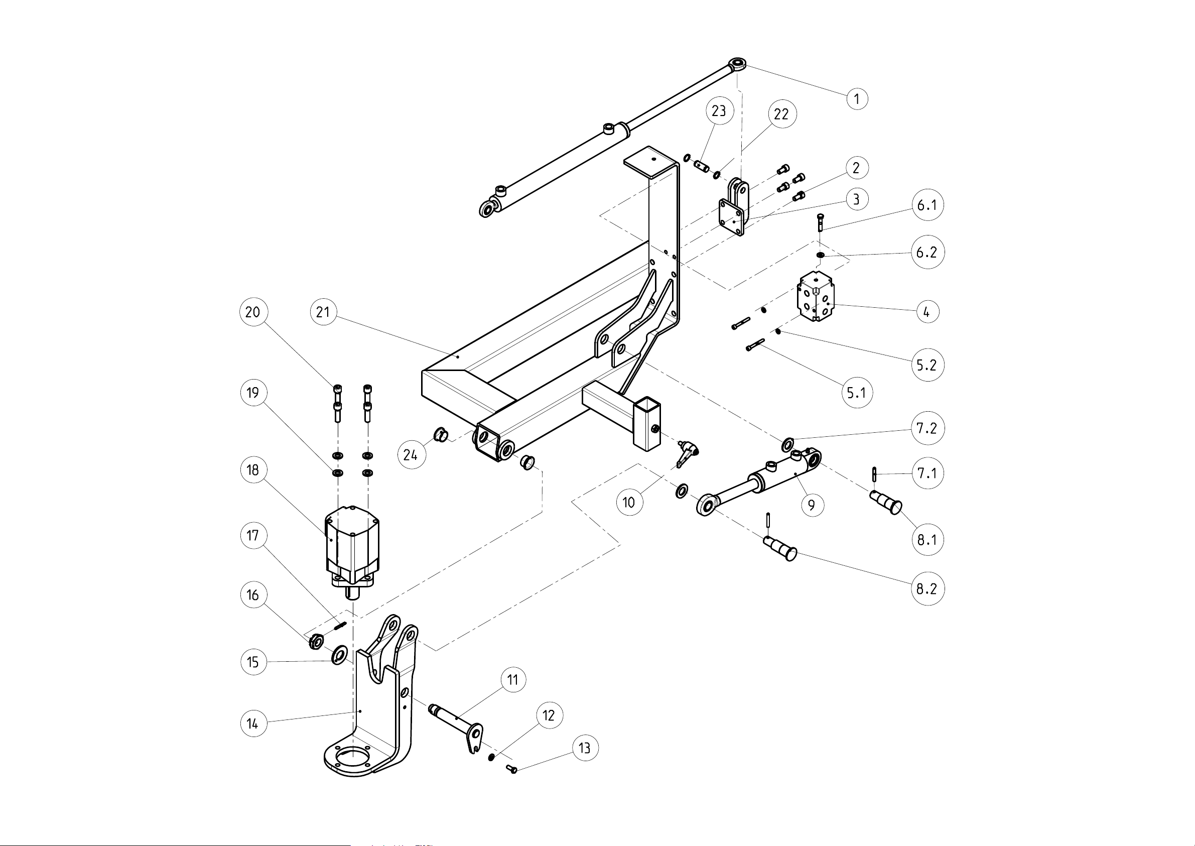
Assembly 1
Main frame
with Hydraulic cylinder

KM 20 TO / TSO
Assembly 1 Main frame with Top link
Pos.
St.
Description DIN
KM 20 TO
KM 20 TSO
Order
-
Nr.
Oder
-
Nr.
1 1 Extension cylinder 32x20x350 - SH-3220350 -
Extension cylinder 40x25x500 - SH-4025500
2 4 Socket head screw M10x20 DIN 912 S 006-067 S 006-067
3 1 Adaptor extension cylinder - 20T0500 -
- KM20TS_5_00
4 1 HPH Block 11106-MICH 011-00 -
11106-MICH 011-00 11106-MICH 011-00
5.1 2 Socket head screw M10x80 DIN 912 S 006-288 S 006-288
5.2 2 Schnorr Disc A10 DIN 6796
S 006-286 S 006-286
6.1 1 Hexagon bolt M8x140 DIN 931 00538140 00538140
6.2 1 Washer A8 DIN 125 S 006-106 S 006-106
7 2 Safety lynch pin 10,5 - 04729105 04729105
8 2 Top link pin cat.2 - OLEB2040 OLEB2040
9 1 Top link (manuell kippen) G-G01 G-G01
10 1 Adjustable clamping lever - 40-5560 40-5560
11 1 Pin NL 120 ø25 - BOL_25123 -
Pin NL 143 ø25 -
BOL
GEW
_25143
12 1 Washer A8 DIN 125 S 006-106 S 006-106
13 1 Hexagon bolt M8x20 DIN 933 S 006-103 S 006-103
14 1 Motor bracket - 20T0301 -
- KM20TS_3_01
15 1 Washer A24 DIN 125 S 006-066 S 006-066
16 1 Castle nut M24 DIN 937 S 006-126 S 006-126
17 1 Slotted straight pin 5x36 DIN 1481
S 006-306 S 006-306
18 1 Hydraulicmotor
Sauer Danfoss OMS 125 *
- 151 F0 502 -
Hydraulicmotor
Sauer Danfoss OMS 200 *
- 151 F0 504
19 4 Schnorr Disc A12 DIN 6796
S 006-110 S 006-110
20 4 Socket head screw M12x35 DIN 912 S 006-053 S 006-053
21 1 Main frame - 20T0200 -
- KM20TS_2_01
22 2 Locking ring 15x1 DIN 471 A15 -
Locking ring 20x1,2 - S 006-845
23 1 Pin ø15x38 - 20T21100 -
Pin ø20x38 - 20T21101
24 2 Glycodur Collar bush 28x25x16,5 - 1170000 1170000
* please tell when ordering spare parts from the information
assisted by the motor nameplate
** Size possibly derogation
MICHAELIS
maschinenbau
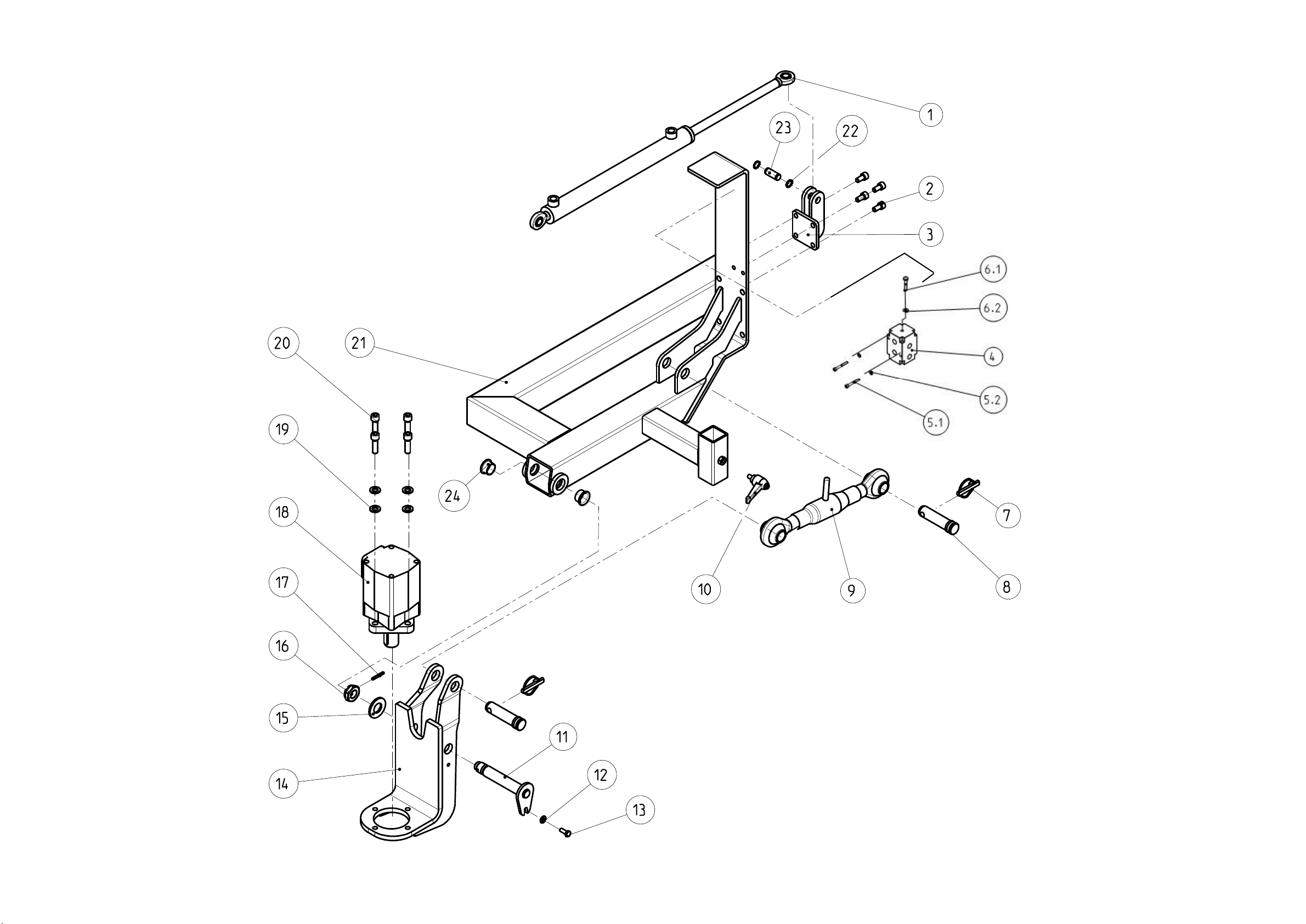
Assembly 1
Main frame
with Top link
This manual suits for next models
3
Table of contents
Other Michaelis Maschinenbau Lawn And Garden Equipment manuals

Popular Lawn And Garden Equipment manuals by other brands


Husqvarna
Husqvarna 42" Collection System Operator and parts manual

AL-KO
AL-KO K-390 manual

Hanover
Hanover HANSQGB-1GRY Instructions for assembly

Gutta
Gutta BS Plus 160 Assembly instructions

Land Pride
Land Pride Food Plot Seeder FPS Specifications

Pontec
Pontec PondoSolar Air 150 Plus operating instructions