Michel's Siderolling Tarp User manual

Siderolling Tarp
Systems Under 9’ 6” Wide
CRANK STYLE
INSTALLATION INSTRUCTIONS
MICHEL’S INDUSTRIES, LTD.
P.O. BOX 119
ST. GREGOR, SK. S0K 3X0
PH:306.366.2184 FX:306.366.2145
EM: sales@michels.ca WWW.michels.ca
Load Loc
Select
Maximizer
Grain Carts
Grain Bagger

Michel’s Industries, Ltd. Generic Siderolling Instructions
Rev: Feb 22/17
Michel’s Industries, Ltd., PH: 306.366.2184 1
This page intentionally left blank
Michel’s Industries, Ltd. Generic Siderolling Instructions
Rev: Feb 22/17
Michel’s Industries, Ltd., PH: 306.366.2184 2
PLEASE READ ENTIRE INSTRUCTIONS BEFORE BEGINNING
Note: THESE INSTRUCTIONS ARE FOR A STANDARD ROLLING TARP THAT LOCKS
CLOSED ON THE DRIVER'S SIDE.
IF ELECTRIC DRIVE, DO THE FOLLOWING FIRST AND THEN PROCEED TO THE ELECTRIC
INSTALLATION INTRUCTIONS
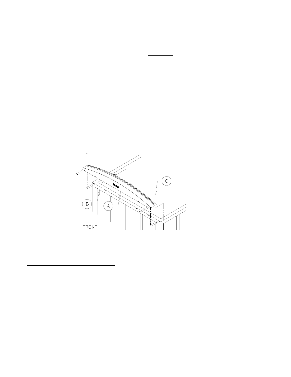
Step 1: Front Hood Installation
(See Figure 1)
Procedure: Center the front hood which has a wind deflector on the front wall of the trailer with the lower 1 inch flange
(A) positioned flush against the outside front edge of the trailer. If the hood is notched on the front corners then the hood
is to be positioned flush against the inside front edge of the trailer. Using a 3/16" drill bit, drill 14 holes through the 1inch
flange and into the box wall (B) placing 2 holes at approximately every 15 inches (see Figure 1). Secure the front hood to
the trailer using the 1/4"x1" lag screws (C) provided. Drill through the top portion on each side of the front hood and
secure using 1/4"x1" lag screws (C).
Step 2: Rear Hood Installation
Option 1 of 2: Semi Rear Hoods
(See Figure 1)
Procedure: Center the rear hood on the rear ledge of the trailer with the lower 1inch flange positioned flush against the
outside rear edge of the trailer. If the rear hood is notched on the corners then it is to be positioned against the inside rear
edge of the trailer.
Note: Continue from Step 1 to complete the rear hood installation.
Figure 1

Michel’s Industries, Ltd. Generic Siderolling Instructions
Rev: Feb 22/17
Michel’s Industries, Ltd., PH: 306.366.2184 3
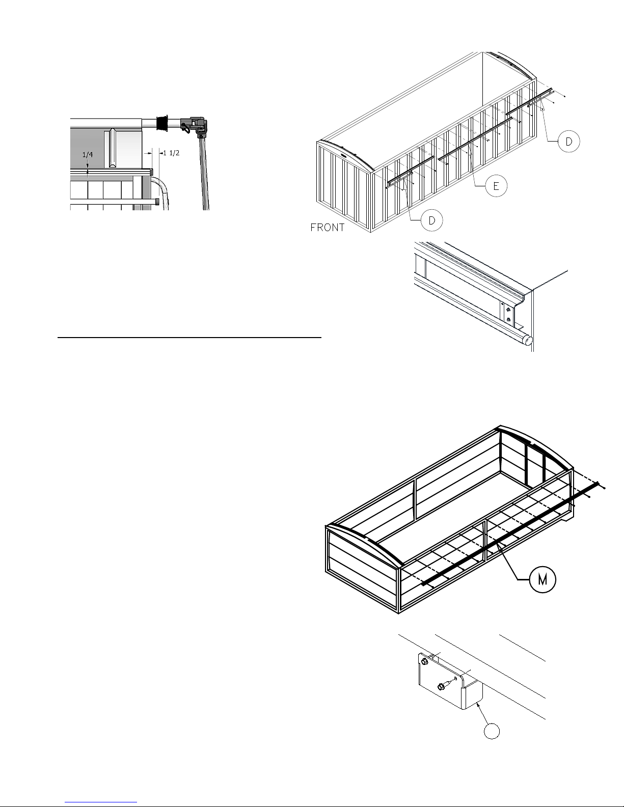
Option 2 of 2: Farm Rear Box Hoods
(See Figure
2)
Procedure: Temporarily place the rear hood on the rear ledge
of
the box with its flange (D) inside the box. Place two
bent
angles (E) into the tubular supports (F), which are welded to
the
underside of the rear hood. Slide the hoop
holder bracket (G)
v
e
r
ticall
y
until it is positioned just below the bend in the bent angle (E).
M
a
rk
hoop holder holes on
the inside box wall and secure the hoop
ho
lde
r
to the box wall using the 1/4"x1" lag screws provided. Apply
f
i
r
m
downward force on the ends of the rear hood and clamp the
hood
down on both sides. Drill a 1/4" hole through the
bo
tt
o
m
area of the bent angle (E). Be sure to drill the hole as close to
t
h
e
bottom of the hoop holder as possible to
prevent the rear hood
fro
m
moving. Insert the hitch pin (H). Weld the bent angle to the tube
(F)
on steel hoods
on
l
y.
For aluminum hoods d
rill a 1/4" hole through the tube
(F)
and the bent angle (E). Secure using the roll pin (I)
prov
ide
d.
Step 3: Optional Ratchet & Strap Installation
(See Figure 3)
Procedure: Insert the bar-hooks through the washer welded to the front (D) and rear (E) hoods. Slide the vinyl ratchet
covers onto the strap before hooking up the ratchet, the location of the ratchet (F) is not critical. Adjust the straps so they
are reasonably tight, once tight slide the ratchet covers over the ratchet assemblies. With ratchet brackets being optional,
they may have to be bolted in with 5/16 truss head bolts, to accommodate ratchet straps in standard hoods.
Note: Do not overtighten the straps or the front and rear hood will deform.
Figure 3
Figure 2

Michel’s Industries, Ltd. Generic Siderolling Instructions
Rev: Feb 22/17
Michel’s Industries, Ltd., PH: 306.366.2184 4
Step 4: Optional Hoop Installation
Please proceed to the Option which best suits your application. If order does not include hoops please proceed
to step 5.
Hoop Holder Spacer Installation
(See Figure 4)
Optional: Use the Hoop Holder Spacers if the top sill on the unit is less than 2 inches deep and does not have the adequate
room to mount the hoops properly, as described in the below steps. These are sent standard for grain carts, spreaders,
gravity wagons and grain baggers to be used on either hoops or tarp stops.
Procedure: Mount the hoop holder spacers (H) where the hoops are to be mounted, attach with two 1/4" x 1" self-
tapping lags. The remaining hoop holder spacers are to be centered according to the length of the unit, and the number of
hoops supplied.
Option 1 of 2: Steel Hoops (used on farm boxes and some semi-trailers)
(See Figure 5, 6)
Procedure: Hoops (J) are provided according to the length of the trailer. Equally space the hoop holders (G) along the
length of the trailer and locate the top edge of the hoop holder 1 inch down from the top edge of the inside trailer wall.
Once in place mark the position of the hoop holder and drill two 3/16" holes into the trailer wall. Secure the hoop holder
using the 1/4"x1" lag screws provided. Follow this procedure to the remaining hoop holders making sure that they are at
the same level, equally spaced, and directly across from each other. Insert bent angle (K) with one end fitted into the
hoop holder (G) and the other end in the hoop (J), then repeat for the opposite side of the trailer. Measure the vertical
distance from the inside of the trailer floor to the top center of the front or rear hood. Record the measured distance.
Center the hoop on the bent angles (K) and measure the vertical distance from the inside trailer floor to the top center of
the hoop. The measurement to the top of the hoop should be 3/4 inch greater than the distance from the trailer floor to
the top of either hood. If the distance is less than or greater than the required 3/4 inch, adjust the hoop and bent angles
accordingly. Weld the hoop to the bent angles making sure that the hoop is parallel with the bent angles (see Figure 5).
Figure 5
Figure 6
Figure 4
H

Michel’s Industries, Ltd. Generic Siderolling Instructions
Rev: Feb 22/17
Michel’s Industries, Ltd., PH: 306.366.2184 5
Option 2 of 2:Aluminum Hoops with Dimple (Typically used with fiberglass center rod in tarp)
(Figure 7, 8)
Procedure: Hoops (J) are provided according to the length of the trailer. Equally space the hoop holders (G) along the
length of the trailer and locate the top edge of the hoop holder 1inch down from the top edge of the inside trailer wall.
Once in place mark the position of the hoop holder and drill two 3/16" holes into the trailer wall. Secure the hoop holder
using the 1/4"x1" lag screws provided. Follow this procedure to the remaining hoop holders making sure that they are at
the same level, equally spaced, and directly across from each other. Insert bent angle (K) with one end fitted into the
hoop holder (G) and the other end in the hoop (J), then repeat for the opposite side of the trailer. Measure the vertical
distance from the inside of the trailer floor to the top center of the front or rear hood. Record the measured distance.
Center the hoop on the bent angles (K) and measure the vertical distance from the inside trailer floor to the top center of
the hoop. The measurement to the top of the hoop should be 3/4 inch greater than the distance from the trailer floor to
the top of either hood. If the distance is less than or greater than the required 3/4 inch, adjust the hoop and bent angles
accordingly. Drill and bolt the hoop to the bent angles using 1/4x1-3/4 inch bolts provided making sure that the hoop is
parallel with the bent angles (see Figure 8).
Step 5: Tension Control Unit & Filler Plate Installation
Please proceed to the Option which best suits your application.
Option 1 of 2: Select or Maximizer (Springs and Cables on front and back for tension)
(See Figure 9)
Note: Standard Rolling Tarps have the Holdback System mounted on the driver side. Reverse rolling tarps have the
Holdback System mounted on the passenger side.
Procedure: To mount the front and rear holdbacks (D), clamp the top flange 1/4 inch lower than the upper edge of the
trailer. Be sure that the 1-1/4 inch square tubing is facing down. Make sure that the PVC cable guide is approximately
1-1/2 inches ahead of the front/rear of the trailer. Predrill a 3/16" hole through the 1 inch flange and into the lip of the
trailer, 1/2” down from the top of the locking flange along the extruded line, spacing each hole at approximately every 15
inches. Secure the holdbacks to the box with the 1/4"x1" lag screws provided. After both holdbacks are secured mount the
filler plate (E).
DRILL & BOLT HERE
Figure 8
K
J
H
G
I
Figure 7
Michel’s Industries, Ltd. Generic Siderolling Instructions
Rev: Feb 22/17
Michel’s Industries, Ltd., PH: 306.366.2184 6
Note: In most cases the filler plate will have to be cut
shorter depending on the length of the trailer. Do not
leave a space between the holdbacks and the filler plate.
Note: When installing holdbacks on a unit with a side wall
as shown in Figure 9A mount a spacer behind the flat to prevent
the holdback from bending and deforming.
Option 2 of 2: Load-Loc (Rope on front for tension)
(See Figure 9B)
Note: Standard Rolling Tarps have the Latch Plate mounted on the driver side.
Reverse rolling tarps have the Latch Plate mounted on the passenger side.
Procedure: To mount the latch plate (M), clamp the top flange 1/4" lower than the upper edge of the box, making sure
that the latch plate is all the way to the front and parallel to the box lip. Predrill a 3/16" hole through the 1 inch flange and
into the lip of the box, spacing each hole at approximately
every 15 inches. Secure the latch plate to the box with the
1/4"x1" lag screws provided.
Note: In most cases the latch plate will have to be cut shorter
depending on the length of the box.
Step 6: Tarp Stop Spacer
Installation
(See Figure 10)
Optional: Use the Tarp Stop Spacers if the top sill on the unit is
less than 2 inches deep and does not have the adequate room to
mount the tarp stops properly, as described in the below steps. These are
sent standard for grain carts, spreaders, gravity wagons and grain baggers
to be used on either hoops or tarp stops.
Procedure: Mount the tarp stop spacers (H) where the tarp stops are
to be mounted, (See Step 7) attach with two 1/4" x 1" self-tapping lags.
The remaining tarp stop spacers are to be centered according to the
length of the unit, and the number of tarp stops supplied.
Figure 9
Figure 9B
Figure 10
H
Figure 9A
Michel’s Industries, Ltd. Generic Siderolling Instructions
Rev: Feb 22/17
Michel’s Industries, Ltd., PH: 306.366.2184 7
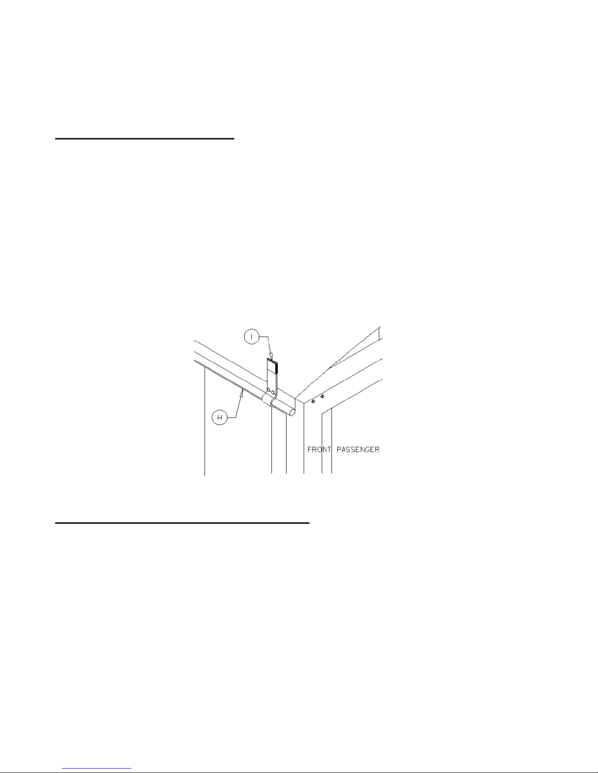
Step 7: Tarp Stop Installation
Please proceed to the Option which best suits your application.
Option 1 of 2: Round Tarp Stop
(See Figure 11)
Procedure: Raise the roll-tube and place it on the top passenger side of the bows and end caps making sure that the roll
tube spline is at the rear of the trailer. Reverse rolls would be placed on the driver side. Roll out the tarp to the driver side
(passenger side for reverse roll). Position the tarp so that the material sits 2 inches in from the face of the front end cap.
Smoothen the tarp out and apply as much tension to it as possible by pulling down on the loose end of the tarp. The
pocket holding the quick release pipe (H) should hang down the side of the trailer approximately 3-1/2 inches. The quick
release pipe (1-1/8” pipe in the tarps pocket) will be held against the side of the trailer by the round tarp stops (I) shown in
Figure 11. Make sure the tarp material is 2 inches in from the face of the front end cap. Mount the front round tarp stop 4
inches in from the front edge of the tarp material. Drill a 5/16" hole through the predrilled holes in the tarp stop and into
the trailer. Secure the stops using the 3/8"x1-1/4" self-threading bolts provided. Next mount the rear tarp stop 4 inches in
from the rear edge of the tarp material, ensure the tarp material is pulled tight from end to end. The remaining round tarp
stops are to be centered according to the length of the trailer. Make sure that the quick release pipe (H) is positioned
parallel with the trailer lip.
Option 2 of 2: Round Flip-Release Tarp Stop
(See Figure 12-14)
Procedure: Locate the front round bracket (J) 4 inches in from the face of the front end cap and 3/4" lower than the top
edge of the trailer. Using a 5/16" drill bit, drill two holes through the predrilled holes in the bracket and into the trailer.
Secure the bracket to the trailer using two 3/8"x1-1/4" self-threading bolts (K) provided. Remove the 1/4"x3" hex bolt (L)
from the flip-release tarp stop (M). Insert the bolt through the bracket (J) and through the tarp stop (M). Secure using the
1/4" lock nut. Torque the bolt appropriately so the flip-release tarp stop will remain in the unlocked position (see Figure
14). Remove the quick pin from the bottom hole of the flip-release tarp stop and adjust the tarp stop so it is in the
unlocked position (see Figure 14). Install the rear bracket 4 inches in from the face of the rear end cap and 3/4" lower than
the top edge of the trailer. Evenly space the remaining flip-release tarp stops along the same side of the trailer making
sure to mount the brackets 3/4" lower than the top edge of the trailer. Position the quick release pipe (N) in the round
brackets (J) (see Figure 12-13). Adjust the tarp so that it sits two inches in from wind deflector on the front end cap. Once
the tarp is in position engage the stops into the locked position (see Figure 14). Reinsert the quick pins through the
bottom holes in the round flip-release stops. (See next page for diagrams)
Figure 11

Michel’s Industries, Ltd. Generic Siderolling Instructions
Rev: Feb 22/17
Michel’s Industries, Ltd., PH: 306.366.2184 8
Step 8: Spring Lock Bracket Installation
(See Figure 15)
NOTE:If it’s a silage end gate the spring lock brackets get mounted on the
s
ide
of the box to allow the end gate to open
and
cl
os
e
.
If ordered as an electric without backup crank skip to step 10.
Drill a 5/16" hole through the predrilled holes in the spring lock bracket
a
nd
into the box. Secure the bracket with the
3/8"x1-1/4" self-threading
bo
lt
s
provided. Lock the tarp in the closed position, engaging the spring lock
(
E
).
Adjust the
angle of the spring lock so that the crank handles
s
eat
s
properly in the spring lock. Make sure that the spring lock
bracket does
no
t
interfere with the
taill
ig
h
ts.
Figure 12 Optional
Figure 13 Optional
Figure 14 Optional
Figure 15
OPTIONAL
SILAGE GATE INSTALLATION

Michel’s Industries, Ltd. Generic Siderolling Instructions
Rev: Feb 22/17
Michel’s Industries, Ltd., PH: 306.366.2184 9
Optional: Universal Crank Lock Bracket
Procedure: (See Figure 16-17)
Assemble the spring lock bracket shown below. Bolt the vertical supports (A) to the middle supports (B), (If Crank Style)
Bolt steel retainers (C) and plastic spring retainers (D) with a 3/8"x1-1/2" hex bolts, flat washer and nylon nut. Bolt the
horizontal supports (E) to the mounting brackets (F) and the middle supports (B) with 3/8" bolts and nylon lock nuts. Do
not tighten bolts until it’s fully installed on the cart. Depending on your cart the mounting bracket will lag into the grain
tank wall or into support tubing’s. If it is mounting into support tubing’s determine the width and bolt together the middle
supports to achieve your desired width. If it is mounting into the wall then set it so it’s about 24" between the vertical
supports. Center the bracket on the back of the cart and mark your holes. Drill 5/16" holes at your marks and secure the
bracket to the cart with 3/8"x1-1/4" self-tapping bolts. With vertical supports secured rotate the horizontal supports up
and lag the mounting brackets to the cart with 3/8"x1-1/4" self-tapping bolts. You may need to shorten the horizontal
supports. Tighten all the bolts on the bracket with steel retainers on an angle shown here (If Crank Style).
On Electric Units the Pivot Arm will attach to this bracket as per instruction manual.
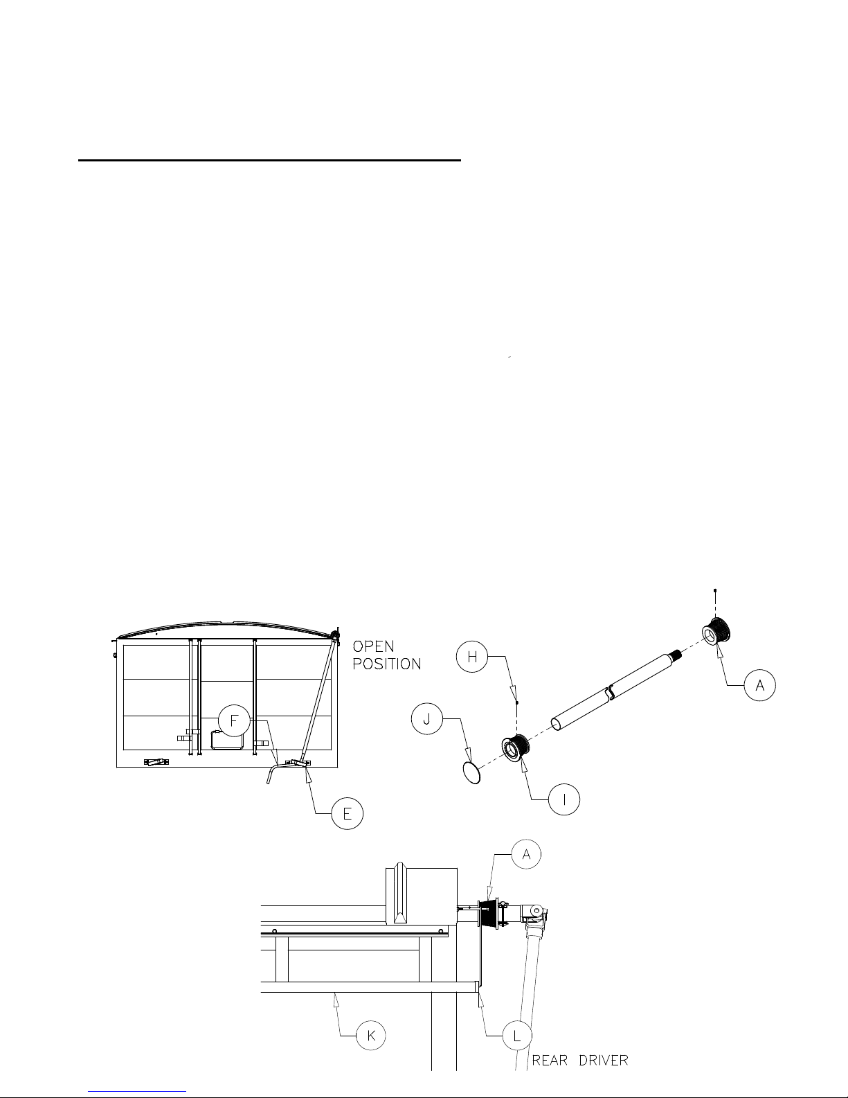
Step 9: Crank & Crank Lock
Installation
(See Figure
18)
Procedure: With the tarp roll hanging under the locking flange,
s
lide
the rear beveled pulley stamped FRONT REVERSE
(A) onto
the
roll-tube with the small flange sliding on first. Slide the
un
i
v
e
rs
al
joint (B) and shaft onto the spline (C) so
that the end of the
c
r
a
nk
is on the outside of the box by approximately 1ft (see Figure
15).
Insert quick pin (D) through
the universal joint. Pull the crank
t
ow
a
rds
the box where the spring lock bracket
(
E
)
is
m
oun
te
d.
Note: The crank handle
should have approximately 30 lbs. of
for
ce
applied to
it
.
If there is not enough force applied to the crank handle then
the
position of the universal joint must be altered.
Adjust the length of the crank handle
(F)
and drill a 1/4" hole through the crank shaft and handle.
F
a
s
te
n
the crank
handle to the shaft with the 1/4"x1-3/4" hex bolt and
1/
4"
nylon lock nut
prov
ide
d.
Figure 18
CLOSED
POSITION
A
F
D
C
EB
Figure 16
Figure 17
Michel’s Industries, Ltd. Generic Siderolling Instructions
Rev: Feb 22/17
Michel’s Industries, Ltd., PH: 306.366.2184 10
Step 10:
Tension
Control
Adjustment
Option 1 of 2: Beveled Cable Pulley Installation
(See Figures
19-21)
Note: When rolling the tarp to the open position, tension must
be
kept on the opposite end of the crank to keep the
tarp rolling
e
v
enl
y.
Procedure: Roll the tarp to the open position. Adjust the angle of the spring lock to properly seat
the
crank
handle
.
Installing cable onto rear beveled pulley:Slide the correct beveled pulley onto the roll tube if not done already from
crank installation, pull the cable from the
r
ea
r
holdback system (K) (see Figure 21) towards the rear beveled
pulle
y
stamped FRONT REVERSE on a standard roll locking closed on the driver’s side (A). Insert cable end into pulley slot
a
nd
rotate beveled pulley 1-3/4 turns for an 8-1/2ft box or 2-1/4 turns
for
an 8ft box. Rotate the pulley from the underside
of it on the large
diamete
r.
Properly position the beveled pulley on the roll-tube so that the
ny
l
on
cable guide (L) on the
holdback lines up with the small diameter
on
the
pulley (see Figure 21). Tighten the 1/4" set screws (H) to hold
the
pulley in
place
.
Installing cable onto front beveled pulley:Pull the cable from
t
h
e
front holdback system towards the front beveled
pulley
s
tampe
d
FRONT STANDARD (I). Repeat the rear beveled pulley
pro
ced
ur
e.
Roll the tarp open and closed several
times checking each time
t
o
make sure that the cable follows in the pulley grooves and the
ta
rp
rolls evenly. If the
cable does not follow in the grooves, move
t
h
e
beveled pulley in or out until the correct position is achieved.
If
the tarp
does not roll evenly, roll the tarp to the open position;
l
oos
e
n
the 1/4" set screws in the front and rear pulleys and
increase the
cable
wrap. This will increase the tension. Do not allow the pulley to
ha
v
e
less than one complete wrap of
cable when the tarp is in the
o
pe
n pos
iti
on.
When finished secure the front beveled pulley cap (J) to the open
e
nd
of
the front beveled pulley
(I). If you are installing an
electric system do not cut
the front of the roll tube, as it will be
needed to drive the tarp.
Note: The front beveled pulley (I) must never ride on the front hood (see Figure 20).
.
Figure 19
Figure 20
Figure 21
Michel’s Industries, Ltd. Generic Siderolling Instructions
Rev: Feb 22/17
Michel’s Industries, Ltd., PH: 306.366.2184 11
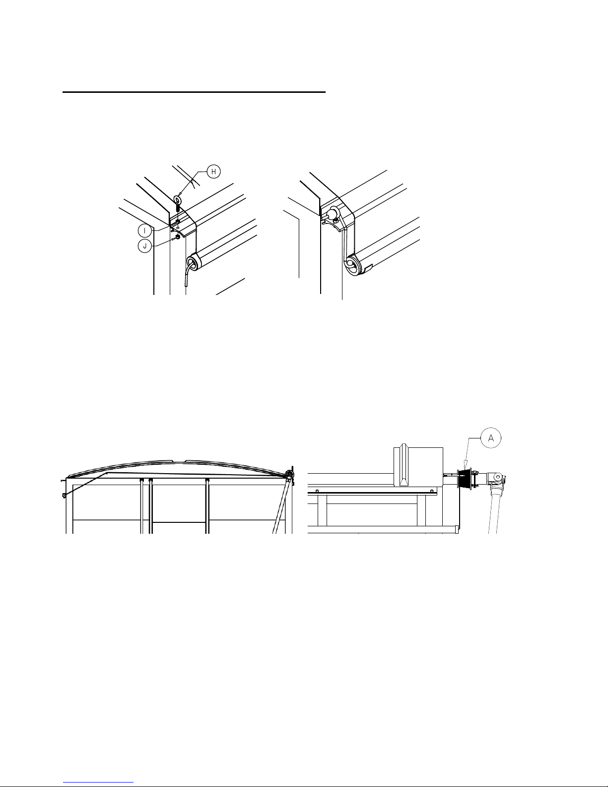
Option 2 of 2: Load-Loc Return Installation
(See Figure
22-23)
Procedure: First drill an 11/32" hole into the front of latch plate 1 1/2" from the edge of the tarp. Fasten the eyebolt (H) to
the latch plate with the 5/16" nut (I) and nylock nut (J). Thread the rope through the eyebolt shown in figure 23 and knot
the end of the rope to prevent it from going through the eyebolt. Cut any extra material off and melt the end to prevent it
from fraying.
Step 11: Rear Hood Bolt
Installation
(See Figure 24 & 25
)
Note: The rear hood bolt (G) prevents the cable from coming
int
o
contact with any obstructions when the tarp
is
o
pe
n.
Procedure: Drill a 1/4" hole through the rear hood at
a
ppro
ximatel
y
18" from the edge of the rear hood and
centered according to
the
height of the hood (see Figure 24). Fasten the 1/4"x4" hex bolt to
the
rear hood; making
sure that the bolt protrudes out far enough for
the
cable to rest on it properly when the tarp is in the open
pos
iti
on.
If Electric see additional instructions included in your kit.
WARNING:
Crank must be locked for transport in either the fully open or fully closed position. Traveling with the tarp in the open
position with the tarp sitting on the hoops will cause premature wear on the tarp material.
WARRANTY:
Michel's Industries warrants their products for a period of one year from date of purchase. Any parts returned to Michel's
Industries LTD. will be shipped prepaid and will be returned F.O.B. St. Gregor, Sk. Canada. We will not assume
responsibility
for shipping, labor or travel expenses. Please Note: We reserve the right to make improvements; therefore specifications
are subject to change without notice.
FOR
INSTALLATION ASSISTANCE
PLEASE CALL MICHEL’S INDUSTRIES, LTD. COLLECT AT (306) 366-2184
Figure 22
Figure 23
Figure 24
Figure 25
Table of contents
Other Michel's Automobile Accessories manuals


