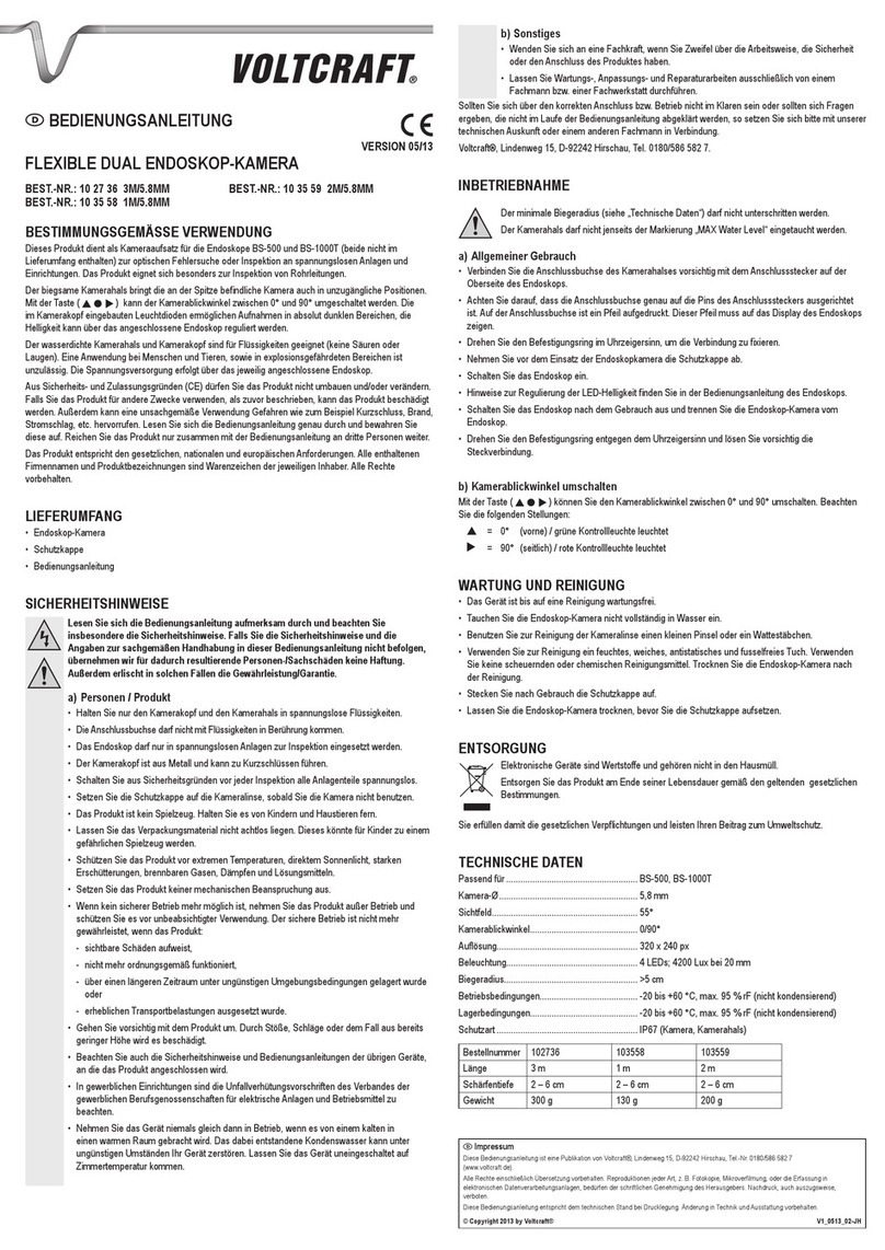
Michell Instruments Condumax II User manual

Condumax II
Hydrocarbon & Water Dew-Point Analyzer
Transportable Sampling System
User’s Manual
97438 Issue 1.3
March 2016

Please fill out the form(s) below for each instrument that has been purchased.
Use this information when contacting Michell Instruments for service purposes.
Instrument
Code
Serial Number
Invoice Date
Location of Instrument
Tag No
Instrument
Code
Serial Number
Invoice Date
Location of Instrument
Tag No
Instrument
Code
Serial Number
Invoice Date
Location of Instrument
Tag No

© 2016 Michell Instruments
This document is the property of Michell Instruments Ltd. and may not be copied or
otherwise reproduced, communicated in any way to third parties, nor stored in any Data
Processing System without the express written authorization of Michell Instruments Ltd.
For Michell Instruments' contact information please go to
www.michell.com
Condumax II Transportable Hydrocarbon
& Water Dew-Point Analyzer Sampling System

Condumax II Transportable
Sampling System User’s Manual
iv 97438 Issue 1.3, March 2016
1 INTRODUCTION .......................................................................................................... 1
2 INSTALLATION............................................................................................................. 4
2.1 Orientation for Transportation/Storage and Operation ........................................... 5
3 OPERATION................................................................................................................. 6
3.1 Sample Flow Start Up Procedure.......................................................................... 7
3.2 Sample Flow Shut Down Procedure...................................................................... 9
3.3 Pressure Regulator Temperature Control ............................................................ 10
4 MAINTENANCE .......................................................................................................... 11
4.1 Filter Element Replacement............................................................................... 11
Contents
Safety ................................................................................................................................ v
Electrical Safety ........................................................................................................... v
Pressure Safety............................................................................................................ v
Toxic Materials ............................................................................................................. v
Repair and Maintenance ............................................................................................... v
Calibration................................................................................................................... v
Safety Conformity ........................................................................................................ v
Abbreviations......................................................................................................................vi
Warnings ............................................................................................................................vi
Appendices
Appendix A Technical Specifications.............................................................................. 13
Appendix B Hazardous Area Certification ...................................................................... 15
B.1 Product Standards ....................................................................... 15
B.2 Product Certification .................................................................... 15
B.3 Global Certificates/Approvals ........................................................ 15
Appendix C Pressure Equipment Directive Compliance Statement ................................... 17
Appendix D EU Declaration of Conformity...................................................................... 19
Appendix E Quality, Recycling & Warranty Information................................................... 21
E.1 Pressure Equipment Directive (PED) 97/23/EC ............................... 21
E.2 Recycling Policy .......................................................................... 21
E.3 WEEE Compliance........................................................................ 21
E.4 RoHS2 Compliance ...................................................................... 22
E.5 Warranty..................................................................................... 22
E.6 REACH Compliance ...................................................................... 23
E.7 Calibration Facilities ..................................................................... 23
E.8 Return Policy ............................................................................... 24
E.9 Manufacturing Quality .................................................................. 24
Appendix F Analyzer Return Document & Decontamination Declaration .......................... 26
Figures
Figure 1 Flow Schematic ..........................................................................................2
Figure 2 Components...............................................................................................3
Figure 3 Hose Connection ........................................................................................4
Figure 4 Horizontal Orientation for Transportation/Storage .........................................5
Figure 5 Vertical Orientation for Operation.................................................................5
Figure 6 Removal of Interface/Display.......................................................................7
Figure 7 Solenoid Valve Location ..............................................................................7
Figure 8 PR1 Adjustment Point .................................................................................8

Condumax II Transportable
Sampling System User’s Manual
Michell Instruments v
Safety
The manufacturer has designed this equipment to be safe when operated using the procedures
detailed in this manual. The user must not use this equipment for any other purpose than that
stated. Do not apply values greater than the maximum value stated.
This manual contains operating and safety instructions, which must be followed to ensure the safe
operation and to maintain the equipment in a safe condition. The safety instructions are either
warnings or cautions issued to protect the user and the equipment from injury or damage. Use
qualified personnel and good engineering practice for all procedures in this manual.
Electrical Safety
The instrument is designed to be completely safe when used with options and accessories supplied
by the manufacturer for use with the instrument.
Pressure Safety
DO NOT permit pressures greater than the safe working pressure to be applied to the instrument.
Refer to Appendix A, Technical Specifications, for pressure information.
Toxic Materials
The use of hazardous materials in the construction of this instrument has been minimized. During
normal operation it is not possible for the user to come into contact with any hazardous substance
which might be employed in the construction of the instrument. Care should, however, be exercised
during maintenance and the disposal of certain parts.
Repair and Maintenance
The instrument must be maintained either by the manufacturer or an accredited service agent. Refer
to www.michell.com for details of Michell Instruments’ worldwide offices contact information.
Calibration
The recommended calibration interval for the Condumax II Transportable is one year, unless it is
to be used in a mission-critical application or in a dirty or contaminated environment in which case
the calibration interval should be reduced accordingly. The instrument should be returned to the
manufacturer, Michell Instruments, or one of their accredited service agents for re-calibration (go to
www.michell.com for contact information).
Safety Conformity
This product meets the essential protection requirements of the relevant EU directives.

Condumax II Transportable
Sampling System User’s Manual
vi 97438 Issue 1.3, March 2016
Abbreviations
The following abbreviations are used in this manual:
AC alternating current
atm pressure unit (atmosphere)
barg pressure unit (=100 kP or 0.987 atm) (gauge)
°C degrees Celsius
°F degrees Fahrenheit
EU European Union
HCdp hydrocarbon dew point
Hz Hertz
lbs pounds
kg kilograms
mm millimeter
Nm3/h normal cubic meters per hour
psig pound(s) per square inch (gauge)
scfh standard cubic feet per hour
V Volts
" inches
% percentage
Warnings
The following general warnings listed below are applicable to this instrument. They are
repeated in the text in the appropriate locations.
!
Where this hazard warning symbol appears in the following
sections, it is used to indicate areas where potentially hazardous
operations need to be carried out.
DANGER
Electric
Shock Risk
Where this symbol appears in the following sections it is used to
indicate areas of potential risk of electric shock.

Condumax II Transportable
Sampling System User’s Manual
Michell Instruments 1
INTRODUCTION
1 INTRODUCTION
The Condumax II Transportable Hydrocarbon Dew-Point Analyzer Sampling System
should be used in conjunction with the Condumax II Hydrocarbon Dew-Point Analyzer
User’s Manual.
The sampling system is in a custom designed, heavy duty, 316 stainless steel carry
case. The case is fitted with six feet on the base (for transportation), and on the base
edge (for upright analyzer system operation). It has six folding carry handles for ease
of mobility by two persons and can be transported between sites using a vehicle.
It features a Condumax II hydrocarbon dew-point analyzer, installed into the sampling
system for automatic measurements that can be taken under supervision by an operator.
The analyzer should not be left alone for extended periods unattended. It is designed
for operator monitored use only.
!
Warning!
This instrument can weigh up to 60kg (132lbs).
Manual lifting and handling should be done by two people
observing appropriate precautions.
NOTE: During transportation, and when not in actual operation, the unit must
be stored on its back (the six main feet opposite the lid face) and with the lid
in place to prevent damage and contamination.
NOTE: When not in use, the sample hoses should be disconnected from their
connections, and the dust protection caps should be replaced.
To assure correct measurement performance of this system in outdoor field use, the
ambient air temperature must be at least 5°C above both the hydrocarbon dew-point
temperature of the process gas sample at the cricondentherm condition, typically 27
barg (392 psig), and water dew point at full process line pressure.
The Condumax II Transportable Hydrocarbon Dew-Point Analyzer Sampling System is
specifically designed for the measurement of hydrocarbon & water dew points in natural
gas. It is a rudimentary sampling system suitable for spot check measurements under
the supervision of an operator. The system is configured with the necessary pressure
let-down and flow control required for measurement at pressure before finally venting
to an atmospheric or a low pressure flare vent line system.
A fast loop bypass flow arrangement is included to reduce sample flow response / time
lag and to enable the filter to be drained automatically of any potential hydrocarbon
liquids and hydrates that may be formed.
The system is configured for connection directly to transmission pipeline natural gas
at, typically, 70 barg (1015 psig) pressure (100 barg/ 1450 psig maximum). Sample
gas pressure reduction is incorporated via an electrically heated regulator for analysis
at intermediate pressure. It has an adjustment range up to 35 barg (500 psig) fitted
with line pressure gauge, 100 barg/ 1450 psig scale (analysis pressure indicated by the
Condumax II Main Unit).

Condumax II Transportable
Sampling System User’s Manual
297438 Issue 1.3, March 2016
INTRODUCTION
Hydrocarbon dew-point analysis pressure is adjusted by a heated pressure regulator in
the range up to 35 barg (500 psig), but it is typical for measurements to be made at
the cricondentherm condition of 27 barg (400 psig), where the highest HC dew-point
temperature will be detected on the retrograde phase envelope.
The water dew point is measured at full pipeline pressure, to determine the highest
water dew point for the gas sample being analyzed.
The complete Condumax II Hydrocarbon Dew-Point Analyzer Sampling System can be
located close to the gas sample take-off point in a potentially explosive environment -
suitable for IEC Zone 1 or 2 hazardous area, NEC Class 1, Division 1, Groups B, C, D.
A set of 3 (2m each) hoses is provided to allow connection to the sample, exhaust and
filter drain/bypass, via a ¼” NPT(M) fitting. Standard fitting assembly practices should
be used. NOTE: Sealing tape must be used to seal fitting to the sample tapping
point. The use of thread sealants is NOT recommended when making measurements
with this type of dew-point analyzer, as contamination of the measurement instruments
is likely to occur from sealant ingestion into the sampling system.
!
The sampling system is designed for temporary installation and
should not be left unattended.
Operator attendance is required at all times. Prolonged periods
of operator absence are not advised.
!
During operation the sampling system must be located in an
environment with a temperature of at least +10ºC (+18°F)
above the highest envisaged dew-point temperature, both
hydrocarbon at cricondentherm and water at line pressure.
It is not advised to operate the analyzer in excessive wind, rain
and snow.
All sample gas wetted metallic parts are constructed from AISI 316L stainless steel with
Viton soft parts that comply with the NACE standard ANSI/NACE-MR0175/ISO-15156
(latest edition). Tube fittings are twin ferrule compression type.
i
h
i
i
i
i
i
Hydrocarbon dew point - measured at cricondentherm condition
Water dew point - measured at line pressure
PG1
PR1
F1
SAMPLE GAS INLET
(100 BARG MAX) NRV1 MV1
NV1
FM1 SAMPLE GAS
OUTLET
BYPASS GAS
OUTLET
HC DEW POINT
WATER DEW POINT
CONDUMAX II
ANALYZER
Figure 1
Flow Schematic

Condumax II Transportable
Sampling System User’s Manual
Michell Instruments 3
INTRODUCTION
The gas handling components are as follows:
Coalescing Filter (F1) Provides protection of the moisture sensor within the
Condumax II instrument.
Pressure Gauge (PG1) Provides indication of sample gas inlet pressure.
Pressure Regulator (PR1) Allows the user to manually set the sample gas analysis
pressure for hydrocarbon dew-point measurement.
Non-return valve (NRV1) Provides system protection from back pressure of vent
gas when sample gas is not flowing.
Metering Valve (MV1) Allows the user to manually set the sample gas flow rate
across the dew-point sensors.
Flowmeter (FM1) Provides indication of the sample gas flow rate across
the dew-point sensors.
Needle Valve (NV1) Allows the user to manually control the bypass flow rate
across the coalescing filter.
Sample inlet
Sample outlet
FM1
MV1
NRV1
Filter Bypass/
Drain outlet
PR1
PG1
F1
NV1
h
h
h
h
h
g
g
g
g
g
g
g
AC Power
gland entry
PR1 Adjustment -
Remove cap. Adjust with 4mm
hex key.
Figure 2
Components

Condumax II Transportable
Sampling System User’s Manual
497438 Issue 1.3, March 2016
INSTALLATION
2 INSTALLATION
The Sampling System should be transported in the horizontal position.
Before operation follow the procedure below:
1. Remove the lid of the case by undoing the 4 latch clips.
2. Bring the sampling system into the vertical position, as indicated on the
label on the side of the case.
3. Make sample gas inlet, outlet and bypass connections using hoses
provided (Minimess 1620 self sealing fittings with ¼” NPT connections).
Maximum inlet pressure 100 barg (1450 psig).
Figure 3
Hose Connection
4. A single phase 240 or 110 V AC (check label on the POWER CIRCUITS
junction box) mains power supply is required to operate the sampling
system and analyzer. Make electrical connections to the POWER CIRCUITS
junction box using suitable M20 cable glands.
Terminals are marked:
L- live, N - neutral, - earth. Minimum cable requirements 3c x 0.75mm2.
NOTE: The user cannot change the specified power supply voltage.

Condumax II Transportable
Sampling System User’s Manual
Michell Instruments 5
INSTALLATION
2.1 Orientation for Transportation/Storage and Operation
!
The Condumax II Transportable must NOT be transported in the
upright/vertical orientation as the shock absorbent design is
only effective in the horizontal position.
Figure 4
Horizontal Orientation for Transportation/Storage
NOTE: Lid must be in place and clasps tightly shut
Figure 5
Vertical Orientation for Operation

Condumax II Transportable
Sampling System User’s Manual
697438 Issue 1.3, March 2016
OPERATION
3 OPERATION
Operation of the Sampling System should be carried out in conjunction with, and
referring to, the Condumax II Dew-Point Hygrometer User's Manual.
Before commencing the start-up procedure ensure that the installation conforms to the
correct hazardous area and local plant standards.
Before any gas pressure is applied, check that all valves and regulators are in the fully
closed position.
!
WARNING
A mandatory purge procedure is stipulated as part of the
certification of the Condumax II product.
This procedure must be completed before any power or signal
connections are made to the Condumax II.
This procedure must also be carried out at any time following
service or maintenance periods that cause any of the Condumax
II or associated gas handling equipment sample lines to be
disconnected.
It is not necessary to carry out this procedure if, during a shut
down period, the sample lines have not been disconnected or if
the power (electrical) connections only have been disconnected.
Before commencement of the start-up procedure ensure that
the power connections to the Condumax II are fully isolated
and, if necessary, observe the stipulated de-energization
period of 45 minutes.

Condumax II Transportable
Sampling System User’s Manual
Michell Instruments 7
OPERATION
3.1 Sample Flow Start Up Procedure
1. Unscrew and remove the Condumax II flameproof enclosure cover after
first loosening the hex grub screw.
2. The user interface/display assembly uses two ¼-turn bayonet style
fasteners, (finger operated), to secure it - turn clockwise to lock, counter-
clockwise to release. The display must be supported once it is removed
from the fasteners. The right hand fastener can be positioned to the left
hand mount, as shown below.
Figure 6
Removal of Interface/Display
3. Locate the solenoid valve and the manual override operating adjuster
(brass screw handle) mounted on the base of the solenoid valve body.
Figure 7
Solenoid Valve Location

Condumax II Transportable
Sampling System User’s Manual
897438 Issue 1.3, March 2016
OPERATION
4. Adjust the solenoid valve to the PURGE POSITION (fully screwed in
clockwise) as shown on the label attached to the solenoid valve.
5. Allow the sample gas to enter the system.
6. Open the Bypass Needle Valve (NV1) one full turn.
7. Adjust the HCdp Flow Metering Valve (MV1) to indicate a sample gas
flow rate of approximately 0.12m³/h (full-scale) on the HCdp Flowmeter
(FM1).
8. Allow the sample gas to purge the system for a minimum of 3 minutes.
9. Re-adjust the solenoid valve to the NORMAL OPERATING POSITION (fully
unscrewed counter-clockwise) as shown on the label attached to the
solenoid valve.
10. Re-fit the Condumax II user interface/display assembly and flameproof
enclosure cover. NOTE: Make sure the hex grub screw is tightened
to prevent inadvertent removal.
11. After the flameproof enclosure cover has been refitted, the Condumax II
is ready for power up. Apply the power supply to the system.
12. The HCdp Pressure Regulator (PR1) is used to set the HCdp gas analysis
pressure. Pressure is indicated on the main display of the Condumax II. It
is normal practice for an analysis pressure of 27 barg (391 psig) to be set for
hydrocarbon dew point, as it is the recognized cricondentherm condition
(pressure at which the highest hydrocarbon dew-point temperature will
exist). To adjust the PR1 - remove the cap to uncover the adjustment
screw. Make the adjustment with a 4mm hex key.
Adjustment
Figure 8
PR1 Adjustment Point

Condumax II Transportable
Sampling System User’s Manual
Michell Instruments 9
OPERATION
Water dew point is measured at the prevailing full line pressure, the condition
at which the highest water dew point will exist.
80
70
60
50
40
30
20
10
0
Pressure, Bara
-40 -30 -20 -10 0 +10
Temperature, ºC
Water and HC
liquids
present in
gas
HC liquids
present in
gas
Wholly gaseous
HC Dew Point
Water Dew Point
Cricondentherm
13. Re-adjust the hydrocarbon & water dew-point sample gas flow rate to
approximately 0.06Nm³/h (2.1scfh) using the Sample Flow Metering Valve
(MV1) and allow the readings to stabilize - the readings from the first 2
or 3 HC dew-point measurement cycles should be disregarded.
3.2 Sample Flow Shut Down Procedure
!
WARNING
If accessing inside the Condumax II Exd housing for
maintenance, a mandatory waiting period is stipulated as part of
the certification of the Condumax II product.
After power down, a minimum period of 45 minutes must be
observed before removing the cover of the Condumax II Exd
housing.
1. Isolate the Sampling System from the sample gas supply line.
2. Allow a short time for the Sampling System to vent/depressurize before
attempting to carry out any work on the system.
3. Isolate the Sampling System from the power supply.
4. If moving, transporting or storing the Condumax II, remove the sample
hoses and refit the caps to the quick connect couplings. Note the
orientation requirements in Section 2.1.

Condumax II Transportable
Sampling System User’s Manual
10 97438 Issue 1.3, March 2016
OPERATION
3.3 Pressure Regulator Temperature Control
DANGER
Electric
Shock Risk
This operation will expose electrical parts operating at high
voltage. Therefore, power must be isolated from the supply for
the Sampling System before making adjustments.
The heated pressure regulator contains an adjustment for the temperature control
set-point (factory-set to approximately +24ºC (+75°F)). It may need adjustment to
increase/decrease the heat requirements to the regulator dependent on the high/low
inlet gas pressure.
To make an adjustment proceed as follows:
1. Unscrew and remove the cover of the junction box after first loosening
the hex grub screw.
2. Adjust the heater output by turning the potentiometer - clockwise to
increase and anti-clockwise to decrease.
3. The seven markings around the potentiometer equate to an approximate
temperature value for the heater of:
1 = +24ºC (+75°F) Recommended setting
2 = +27ºC (+80°F) May be advised by Michell dependent upon application
3 = +29ºC (+85°F) May be advised by Michell dependent upon application
4 = +35ºC (+95°F) May be advised by Michell dependent upon application
5 = +43ºC (+110°F) May be advised by Michell dependent upon application
6 = +54ºC (+130°F) Should not be set
7 = +79ºC (+175°F) Should not be set
4. Replace the junction box cover and tighten the hex grub screw.

Condumax II Transportable
Sampling System User’s Manual
Michell Instruments 11
MAINTENANCE
4 MAINTENANCE
!
WARNING
This system operates under high pressure. Isolate power and
sample gas and depressurize the Sampling System before
attempting any maintenance or servicing.
Maintenance of the Condumax II Transportable Hydrocarbon Dew-Point Analyzer
Sampling System should be carried out with reference to the Condumax II Hydrocarbon
Dew-point Analyzer User’s Manual.
Routine maintenance of the system is confined to filter element replacements.
Calibration requirements and methods of implementation are described in the
Condumax II Hydrocarbon Dew-Point Analyzer User's Manual.
4.1 Filter Element Replacement
Life expectancy of the filter element is dependent upon operating conditions in each
specific application. As a minimum, it is recommended that the filter element be cleaned
or changed every 12 months. If inspection of the removed element shows that it is
in good/poor condition after 12 months operation then the period between cleaning/
replacement may be reduced/increased accordingly.
To replace the filter element, proceed as follows:
1. Isolate the sampling system from sample gas supply.
2. Allow a short time for the Sampling System to vent/depressurize before
attempting to carry out any work on the system.
3. Disconnect the tube from the drain port of the filter bowl by releasing the
tube fitting nut. DO NOT undo/loosen the tube fitting body, i.e. threaded
joint!
4. Unscrew and remove the filter bowl and then the filter element. NOTE:
the filter bowl is sealed with a Viton O-ring.
5. Discard the old used filter element and replace with a new filter element
(Michell item no. SSF-CF-LON-10PK).
6. Replace the filter bowl, ensuring the O-ring is correctly seated and
reconnect the tube to the drain port. Tighten securely.
7. Resume operation in accordance with the Start-Up Procedure (Section
2.2).

Condumax II Transportable
Sampling System User’s Manual
12 97438 Issue 1.3, March 2016
APPENDIX A
Appendix A
Technical Specifications

Condumax II Transportable
Sampling System User’s Manual
Michell Instruments 13
APPENDIX A
Appendix A Technical Specifications
General Specifications
Case 316 stainless steel
Case Dimensions 640 x 490 x 330mm (25 x 19.3 x 13")
Gas Connections Minimess quick connect, 316 stainless steel braided
Length - 3m each hose
Gas Flow Rate 0.06Nm³/h (2.1scfh)
Gas Pressure 100 barg (1450 psig) max
Filter
Coalescing, Borosilicate, glass-bonded micro-fibers bonded with
Kynar fluorocarbon (PVDF) resin
(99.5% removal of 0.1 micron particles and aerosols (BS4400)
Power Supply 110 V AC, 60Hz (CSA) OR 240 V AC, 50Hz (ATEX)
Gas Wetted Bore PTFE, 2mm internal diameter
Process Connection 316 stainless steel, 1/4 NPT male
Power Consumption < 300 W
Weight 60kg (132lbs) max

Condumax II Transportable
Sampling System User’s Manual
14 97438 Issue 1.3, March 2016
APPENDIX B
Appendix B
Hazardous Area Certification
Other manuals for Condumax II
3
Table of contents
Other Michell Instruments Analytical Instrument manuals
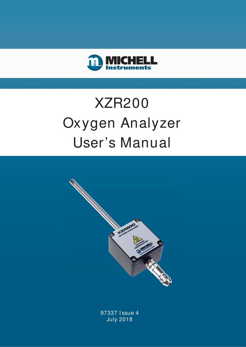
Michell Instruments
Michell Instruments XZR200 User manual
Michell Instruments
Michell Instruments XTP601 User manual
Michell Instruments
Michell Instruments Liquidew I.S. User manual
Michell Instruments
Michell Instruments XTP601 User manual
Michell Instruments
Michell Instruments XTC601 User manual
Michell Instruments
Michell Instruments XZR500ST User manual


