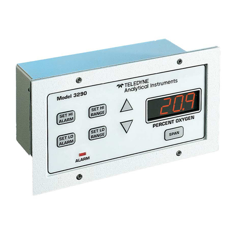
Michell Instruments XZR200 User manual

XZR200
Oxygen Analyzer
User’s Manual
97337 Issue 4
July 2018

Please fill out the form(s) below for each instrument that has been purchased.
Use this information when contacting Michell Instruments for service purposes.
Instrument
Code
Serial Number
Invoice Date
Location of Instrument
Tag No
Instrument
Code
Serial Number
Invoice Date
Location of Instrument
Tag No
Instrument
Code
Serial Number
Invoice Date
Location of Instrument
Tag No

© 2018 Michell Instruments
This document is the property of Michell Instruments Ltd. and may not be copied or
otherwise reproduced, communicated in any way to third parties, nor stored in any Data
Processing System without the express written authorization of Michell Instruments Ltd.
XZR200
For Michell Instruments' contact information please go to
www.michell.com

XZR200 User’s Manual
iv 97337 Issue 4, July 2018
Contents
Safety ................................................................................................................................vi
Electrical Safety ...........................................................................................................vi
Pressure Safety............................................................................................................vi
Toxic Materials .............................................................................................................vi
Repair and Maintenance ...............................................................................................vi
Calibration...................................................................................................................vi
Safety Conformity ........................................................................................................vi
Abbreviations.....................................................................................................................vii
Warnings ...........................................................................................................................vii
1 INTRODUCTION ................................................................................................1
1.1 Features ............................................................................................................ 1
1.2 Description ....................................................................................................... 2
2 OPERATION ......................................................................................................3
2.1 Configuration .................................................................................................... 3
2.2 Initial Sensor Drift and Active Burn-In ................................................................. 4
2.3 XZR200 Variations .............................................................................................. 5
2.4 Life Span of the Analyzer .................................................................................... 5
3 INSTALLATION ..................................................................................................6
3.1 Mounting and Orientation.................................................................................... 6
3.1.1 Ambient Monitoring ...................................................................................... 7
3.2 Electrical Connections ......................................................................................... 7
3.3 System Block Diagram ....................................................................................... 8
3.4 RS232 Communication Settings .......................................................................... 8
3.5 RS232 Operation ............................................................................................... 9
3.6 RS232 User-Configurable Options ....................................................................... 9
3.6.1 Menu Screens .............................................................................................. 9
3.6.2 Changing the Menu Access Password ............................................................ 9
3.6.3 Variable Output Filtering (Td Averaging) ...................................................... 10
3.6.4 Changing the Automatic Calibration Value .................................................... 10
3.6.5 Adjusting the Minimum and Maximum Ranges of the Analog Outputs ............ 11
3.7 Continuous Data Streaming .............................................................................. 12
4 CALIBRATION..................................................................................................13
4.1 Automatic Calibration ....................................................................................... 13
4.2 Manual Calibration ........................................................................................... 13
5 GOOD MEASUREMENT PRACTICE .....................................................................14
5.1 Error Conditions .............................................................................................. 14
5.2 Sensor Operating Tips ..................................................................................... 14
5.2.1 Operating the Sensor in Aggressive Humid Environments .............................. 14
5.2.2 Protecting from Water Droplets ................................................................... 15
5.2.3 Cross Sensitivity With Other Gases .............................................................. 15
5.2.4 Using the Sensor with Silicones ................................................................... 16

XZR200 User’s Manual
Michell Instruments v
Figures
Figure 1 Jumper Configuration for Output Selection ...................................................3
Figure 2 Jumper Configuration for Calibration Type & Range Selection.........................4
Figure 3 Mounting and Orientation ...........................................................................6
Figure 4 Electrical Connections .................................................................................7
Figure 5 System Block Diagram ................................................................................8
Figure 6 COM Port Settings ......................................................................................8
Figure 7 Sensor Damage........................................................................................14
Appendices
Appendix A Technical Specifications.............................................................................. 18
Appendix B Theory of Operation ..................................................................................21
Appendix C Quality, Recycling & Warranty Information................................................... 25
Appendix D Analyzer Return Document & Decontamination Declaration .......................... 27

XZR200 User’s Manual
vi 97337 Issue 4, July 2018
Safety
The manufacturer has designed this equipment to be safe when operated using the procedures
detailed in this manual. The user must not use this equipment for any other purpose than that
stated. Do not apply values greater than the maximum value stated.
This manual contains operating and safety instructions, which must be followed to ensure the safe
operation and to maintain the equipment in a safe condition. The safety instructions are either
warnings or cautions issued to protect the user and the equipment from injury or damage. Use
qualified personnel and good engineering practice for all procedures in this manual.
Electrical Safety
The instrument is designed to be completely safe when used with options and accessories supplied
by the manufacturer for use with the instrument. The input power supply voltage limit is 24 V ±10%.
Pressure Safety
The XZR200 is designed to be operated at atmospheric pressures. However, it is possible to measure
in the range 0 to 25% O2at pressures up to 5 barg (72.5 psig) without damage to the unit. The unit
will require calibration at the operating pressure and a separate pressure transducer feeding into
your control system may also be required.
Toxic Materials
The use of hazardous materials in the construction of this instrument has been minimized. During
normal operation it is not possible for the user to come into contact with any hazardous substance
which might be employed in the construction of the instrument. Care should, however, be exercised
during maintenance and the disposal of certain parts.
Repair and Maintenance
The instrument must be maintained either by the manufacturer or an accredited service agent. Refer
to www.michell.com for details of Michell Instruments’ worldwide offices contact information.
Calibration
The recommended calibration interval for the XZR200 is between one and three months. This
duration may be shorter or longer dependent on installation, application and customer preferences.
Safety Conformity
This product meets the essential protection requirements of the relevant EU directives.

XZR200 User’s Manual
Michell Instruments vii
Abbreviations
The following abbreviations are used in this manual:
°C degrees Celsius
°F degrees Fahrenheit
DC direct current
EU European Union
kg kilogram(s)
l/min liters per minute
lb pound
mA milliampere
max maximum
min minute(s)
scfh standard cubic feet per hour
Td cycle time to evacuate and re-pressurize the sealed cell
Td averaging counting x number of cycles and averaging the result
V Volts
% percentage
" inches
Warnings
The following general warning listed below is applicable to this instrument. It is repeated
in the text in the appropriate locations.
!
Where this hazard warning symbol appears in the following
sections, it is used to indicate areas where potentially hazardous
operations need to be carried out.

XZR200 User’s Manual
Michell Instruments 1
INTRODUCTION
1 INTRODUCTION
The XZR200 measures the partial pressure of O2utilizing a Zirconium Dioxide (ZrO2)
sensor cell in Safe Area (general purpose) applications.
This user manual will show you how to measure oxygen using the XZR200 oxygen
analyzer.
In the following sections you will learn about:
• Zirconium Dioxide technology
• Analyzer components
• Installation
• Operation
• Calibration
Please read the manual carefully and pay particular attention to any safety warnings
and notifications.
Note: Warnings and items of importance will be marked with bold text.
1.1 Features
• Accurate linear configurable outputs: 4-20mA & 0-10 V DC or RS232
• Selectable output measurement ranges: Standard ranges of 0 to 25% O2
and 0 to 100% O2or fully adjustable via RS232 when configured in 0 to
100% O2mode
• Externally triggered automatic or manual calibration
• Calibrated in ambient air (20.7% O2) or in any other known O2concentration
• Cycling 3.3 V DC logic output allows direct monitoring of the O2sensor
pump cycle for diagnostic purposes
• Selectable output filtering allows adaptive, fast and dynamic, or slow and
stable output
• IP65 die-cast aluminum case with stainless steel probe 210mm (8.27") or
400mm (15.75")

XZR200 User’s Manual
297337 Issue 4, July 2018
INTRODUCTION
1.2 Description
The XZR200 is designed to determine the oxygen concentration in air or inert gas
mixtures within a temperature range of -100 to +250°C (-148 to +482°F). The high
temperature option increases the maximum allowable sample temperature to +400°C
(+752°F). The XZR200 is particularly suitable for measuring oxygen in areas that are not
easily accessible, or in closed systems such as ventilation pipes, flues and containers.
The XZR200 can be user-configured to output measuring ranges of 0 to 25% O2or
0-100% O2. The entire measurement range is linear in both cases. Factory default is
0 to 25% O2. When configured for 0 to 100% O2the user can also modify the analog
output ranges to suit their application. The oxygen concentrations are simultaneously
output via 2 output channels (4-20mA and 0 to 10 V DC or RS232 Rx and Tx) - both
channels are referenced to the system ground (GND).
The outputs can be configured to either 4-20mA and 0 to 10 V DC or RS232 interface.
Prior to shipping, all XZR200's are preconfigured with a measuring range of 0.1% to
25% volume O2with linear 4-20mA and 0 to 10 V DC outputs. All settings can be
changed by the customer, should the measurement or interface requirements change,
by simply altering the position of jumper links on the PCB. The electronics are housed
in an IP65 die-cast aluminum housing.
The oxygen sensor is mounted in the tip of the stainless steel probe and is protected
by a stainless-steel sintered cap which acts as both a large particulate filter and also as
a flame trap.
A digital 3.3 V DC logic output cycles at the same frequency as the electrochemical
pumping action of the oxygen sensor during normal operation. This provides a real time
sensor health check; if the output ceases to cycle the sensor has entered a start-up or
fault state. The digital output is also used during the calibration process to indicate the
interface status.
A green on-board LED mirrors the CYCLE output and can be used to visually determine
the sensor status or during the calibration process. The red LED indicates the unit has
power applied.
The sensor measures the partial pressure of oxygen within the measurement gas and not
the oxygen concentration. In order to output an oxygen concentration (%) the XZR200
must be calibrated (more specifically re-referenced) in a known gas concentration,
typically normal air. Calibration data is stored on power loss.
The automatic or manual calibration function is user-configurable. Regular calibration
removes the effects of application and atmospheric pressure changes and also eliminates
any sensor drift that may occur during the first few hundred hours of operation.

XZR200 User’s Manual
Michell Instruments 3
INSTALLATION
2 OPERATION
The XZR200 is designed as a fit and forget device. Once configured, installed and all
electrical connections made, there are no further operating instructions required. Only
routine inspection and calibration of the unit is required. The inspection is more a
preventative measure to ensure the surrounding environment or any other factor is not
damaging or interfering with the performance of the analyzer.
2.1 Configuration
The XZR200 may be reconfigured at any time by adjusting the position of the header
pin jumper links on the interface PCB.
!
Prior to re-configuration the unit MUST be powered down. The
jumper links MUST also be re-positioned correctly and in the
correct orientation.
Failure to adhere to the above could result in product damage.
Products damaged due to incorrect configurations will not be
covered under warranty.
1. Power down the analyzer
2. Remove the lid using a Phillips (cross head) screwdriver.
3. Adjust the position of the jumper links to the desired configuration.
Thin-nosed pliers should be used to remove and replace the jumper links. Ensure the
jumper links are correctly seated before reapplying the power.
JUMPER LINKS
RS232 Rx
0 to 10 VDC OUTPUT
RS232 Tx
4-20mA OUTPUT
Figure 1
Jumper Configuration for Output Selection
When selecting the output, you must choose either 4-20mA and 0 to 10 V DC or RS232
Tx and Rx. Ensure the jumper links are always inserted horizontally between 2 adjacent
pins. Place the jumper link(s) into the relevant position(s). Two jumper links are required
for RS232 (positions 1 & 3) and only one jumper link is required for either 0-10 VDC
(position 2) or 4-20 (position 4). NOTE: If only using one jumper link make sure
the other jumper link is stored safely for future use.

XZR200 User’s Manual
497337 Issue 4, July 2018
INSTALLATION
Using the jumper settings shown below, both the measurement range and the calibration
option can be set. The following options are available:
Measuring range: 0-25% or 0-100%
Calibration: Auto cal or manual calibration
JUMPER LINKS
25% O2RANGE
100% O2RANGE
MANUAL CAL
AUTO CAL
Sensor LED
Figure 2
Jumper Configuration for Calibration Type & Range Selection
2.2 Initial Sensor Drift and Active Burn-In
NOTE: In the first 200 hours the sensor output can drift by up to ±3%.
This is due to a number of factors including:
• impurities in the Zirconium Dioxide migrating to the surface of the platinum
electrode bond which alters the catalytic properties.
• heater coil ageing.
• the internal stainless steel surface of the cap becoming less reflective due
to thermal oxidation.
Regular calibration removes the effect of initial sensor drift as the sensor output is
constantly re-referenced against the known calibration gas. However, if regular
calibration is not possible and the output is required to have stabilized prior to use in
the application then it may be necessary to actively burn-in the sensor.
Active burn-in involves operating the sensor normally in a controlled atmosphere where
the exact PPO2is known. If this is normal air then all weather data must be recorded
and the PPO2calculated.
The level of stability required will be dependent on the application specifications.
However, in general the output can be considered stable when the value has varied by
less than ±0.2% of reading in the previous 48 hours.
When performing an active burn-in, measurements should be taken at regular intervals
and the environmental temperature should also be kept constant to negate any
temperature dependence the sensor output may exhibit.

XZR200 User’s Manual
Michell Instruments 5
INSTALLATION
2.3 XZR200 Variations
The XZR200 will be set-up as one of the following variations (as per customer order):
XZR200-B1-C1 XZR200, standard temperature up to +250ºC (+482ºF)
210mm (8.27") probe
XZR200-B1-C2 XZR200, standard temperature up to +250ºC (+482ºF)
400mm (15.74") probe
XZR200-B2-C1 XZR200, high temperature up to +400ºC (+752ºF)
210mm (8.27") probe
XZR200-B2-C2 XZR200, high temperature up to +400ºC (+752ºF)
400mm (15.74") probe
2.4 Life Span of the Analyzer
Dependent on the application, the XZR200 sensor will have a variable lifespan. In
ambient temperatures with inert gases, the sensor should last approximately 7 years.
For combustion processes the following guide should be used:
Natural gas Approximately 5 to 7 years
Biogas Approximately 3 to 4 years
Biomass Approximately 2 years
Coal and Oil Approximately 1 to 2 years
!
If there is zero oxygen in the sample, the sensor will still try to
pump O2within the ZrO2and this will, in time, damage the ZrO2
and degrade its performance. It is, therefore, imperative that
the sensor is not used for prolonged periods in very low oxygen
environments (0.1% O2), especially in reducing atmospheres (an
atmosphere in which there is little free oxygen and oxygen is
consumed).

XZR200 User’s Manual
697337 Issue 4, July 2018
INSTALLATION
3 INSTALLATION
!
When installing the sensor do not use any lubricants or grease
which may contain silicone.
!
The sensor is located in the tip of the probe and is heated to
700°C (1292°F).
Do NOT touch the probe tip with bare hands as this will cause
damage to skin.
3.1 Mounting and Orientation
!
The XZR200 should be grounded (earthed) via the probe as well
as through the cable.
When using the XZR200 in a combustion process the diagram below shows the correct
mounting and orientation. The downward angle of the probe tip will protect the sensor
from dust settling or moisture sitting in the tip and damaging the sensor.
A 12mm fitting with a retaining nut that can be welded to the process and fix the probe
in position. A suitable O-ring should be used to ensure a good seal.
Housing
15°
Partition
Bar Probe
O-Ring Nut
Weld Socket
Partition
Atmospheric Air
+60°C Max Gas Mixture
+250°C Max
+400°C Max
Figure 3
Mounting and Orientation

XZR200 User’s Manual
Michell Instruments 7
INSTALLATION
3.1.1 Ambient Monitoring
When used for ambient monitoring or confined spaces, there are two holes on the rear
of the electronics case that can be utilized for mounting (see Dimensions in Appendix
A). If placed tight against a wall or surface, a heat shield may be required to protect the
surface from being damaged.
3.2 Electrical Connections
g
h
45°
1
23
4
5
6
78
Pin Number Description
1 24 V DC ± 10%
2 NC
3 0 to 10 V DC / RS232 Rx
4 4-20mA / RS232 Tx
5 Cycle
6 Calibrate
7 GND (0 V DC)
8NC
Connector Body Housing/Probe Earth
1
2
6
5
4
3
7
8
NOTE: The above view of the electrical
connections is shown from the mating side.
Here are the connections as viewed
from the back of the connector and this
should be used for wiring purposes.
Figure 4
Electrical Connections
Housing connector: 99 3481 578 08
Mating connector: 713 99 1486 812 08
(mating connector supplied loose with each product)
Output pins 3 and 4 are both referenced to the supply GND (pin 7). Due to high
current flow in the supply GND - when monitoring the 0 to 10 V DC output (pin 3) it
is recommended that a separate GND wire for the measurement system is taken from
pin 7. This removes errors due to voltage drops in the power supply connections.

XZR200 User’s Manual
897337 Issue 4, July 2018
INSTALLATION
3.3 System Block Diagram
V V RS232 Rx RS232 Tx
PC or RS232
SERIAL DEVICE
RS232 GND
CYCLE
MONITOR
GND
External Calibration
Switch
4-20mA
(Pin 4)
0 - 10 V DC
(Pin 3)
OR
RS232 Tx
(Pin 4)
RS232 Rx
(Pin 3)
XZR200
OXYGEN ANALYZER
CYCLE
(Pin 5)
CALIBRATE
(Pin 6)
+24 V DC
(Pin 1)
100 to
600Ω
GND
(Pin 7)
+
-
+24 V DC
POWER
SUPPLY
Figure 5
System Block Diagram
3.4 RS232 Communication Settings
When connecting the XZR200 via the RS232 connections, ensure Tx goes to Rx of the
PC and Rx goes to Tx of the PC.
The XZR200 communicates via standard COM port settings that are default on most
PC's and many other RS232 compatible devices. If, however, communication problems
are occurring, the settings below can be used to configure the PC or device COM Port.
Figure 6
COM Port Settings

XZR200 User’s Manual
Michell Instruments 9
INSTALLATION
3.5 RS232 Operation
With the RS232 outputs connected to a PC or any other RS232 compatible device the
user has the ability to access two modes of operation, continuous data streaming and
the menu screens.
Programs for communicating via PC serial RS232 are readily available.
3.6 RS232 User-Configurable Options
3.6.1 Menu Screens
If the XZR200 receives an ENTER command from the connected PC or device, it
automatically enters the password screen and stops outputting O2% and Td values.
After the correct password is input followed by the ENTER key, the menu screens are
accessed. The menu screens are primarily for diagnostics and information, although
there are user-configurable options that may be changed. These are: the amount of
output filtering (averaging), the automatic O2calibration %, and the analog output
ranges. All three processes are further described below. The menu access password
may also be changed by the user, as shown below.
3.6.2 Changing the Menu Access Password
The password is factory set to ‘default’. However this may be changed to a user specific
password.
1. Connect the XZR200 via the RS232 interface to the PC.
2. Press
ENTER then enter your current security password.
3. Press
ENTER to access the menu screen.
4. In the Configuration Menu (menu 2) enter ‘3’ to access the password
menu screen.
5. Enter the new password then press ENTER to save.
The new password is now stored in memory and is retained on power loss.
Pressing ESC returns the screen to the previous menu.

XZR200 User’s Manual
10 97337 Issue 4, July 2018
INSTALLATION
3.6.3 Variable Output Filtering (Td Averaging)
The XZR200 is factory set to use adaptive output filtering to give an optimum balance
between output stability and response to oxygen changes. However, this balance may
be altered by the customer to suit the needs of the application.
1. Connect the analyzer via the RS232 interface to the PC. See Section 2.1
on Configuration.
2. Press
ENTER then enter your security password. Press ENTER to access
the menu screen.
3. In the Configuration Menu (menu 2) enter the Td average screen (Option
2 - Enter Td Averaging).
4. The number entered should be between 0 and 200. 0 for adaptive
filtering (recommended), 1 for very fast and dynamic output response
but relatively unstable, to 200 for an extremely stable output but very
slow response to oxygen changes.
5. Press
ENTER to save.
The new averaging value is now stored in memory. This value is retained on power loss.
Td output by the XZR200 is proportional to the partial pressure of oxygen (PPO2) and
the typical value of Td per mbar of PPO2 is 1.05ms ±15%.
For example if we have 20.7% oxygen in 1000mbar barometric pressure the PPO2 value
would be 207mbar. This equates to a typical Td of 207*1.05=217.5ms.
To convert the XZR200 Td output back to ms the number must be multiplied by 0.000048
which is the clock period of the microprocessor in seconds.
So for the example above a Td value of 217.5ms would be output from the XZR200 as,
0.2175/0.000048 = 4531.
3.6.4 Changing the Automatic Calibration Value
The system is factory set to automatically calibrate to 20.7% O2to allow simple
calibration in normal air. The auto calibration value is factory set to 20.7% to take into
account average humidity in the atmosphere. If a calibration with a gas of a different
known oxygen concentration is required, then the factory set value may be changed via
the RS232 interface.
1. Connect the XZR200 via the RS232 interface to the PC. See Section 2.1
on Configuration.
2. Press
ENTER then enter your security password. Press ENTER to access
the menu screen.
3. In the Configuration Menu (menu 2) enter the auto calibration value
screen (Option 1 - Enter Auto Calib).
4. The number entered should be the oxygen concentration (%) of the
calibration gas to 2 decimal places. Press ENTER to save.

XZR200 User’s Manual
Michell Instruments 11
INSTALLATION
The new Automatic Calibration value is now stored in memory. This value is retained on
power loss.
If calibration is required with a different gas of known O2concentration, and access to
the RS232 menus with a PC is not available in order to change the calibration percentage,
a manual calibration must be performed.
3.6.5 Adjusting the Minimum and Maximum Ranges of the Analog Outputs
(4-20mA and 0 to 10 V DC)
The XZR200 is factory default to output a range of 0-25% O2via its two analog outputs.
This range can be expanded to 0 to 100% O2as described in Section 2.1. When the unit
is reconfigured to output 0 to 100% O2the user also has the option to fully customize
the output ranges via RS232. This is extremely useful in applications where the O2
variation is within a narrow band as it allows the analog outputs to be tailored to this
limited range.
1. Ensure the XZR200 is configured for 0 to 100% and RS232 operation. See
Section 2.1 on Configuration.
2. Connect the XZR200 via the RS232 interface to the PC.
3. Press
ENTER then enter your security password. Press ENTER to access
the menu screen.
4. In the Configuration Menu (menu 2) enter the maximum range screen
(Option 3 - Enter O2Max Range).
5. The number entered should be between 1.00 and 100.00 to represent the
maximum output range. The number must also be greater than the saved
minimum range.
6. Press
ENTER to save and ESC to return to the Configuration Menu.
7. Enter the minimum range screen (Option 4 - Enter O2Min Range).
8. The number entered should be between 0.00 and 99.00 to represent the
minimum output range. The number must also be less than the saved
maximum range.
9. Press
ENTER to save.
The new ranges are now stored in memory and are retained on power loss.
An example of changing the min and max output ranges would be in a normal air
atmosphere where the O2range is between 20 to 21%. The user could set the minimum
output range to 19% and the maximum output range to 22% and the outputs would
vary linearly in between. The min and max ranges lock out the outputs at the set limits
- so 19% O2or lower would set the analog outputs to 0 V DC / 4mA and 22% O2or
higher would set the analog outputs to 10 V DC / 20mA.
NOTE: The min and max range adjustment does not apply to the RS232 output
and is overruled if the unit is reconfigured for 0 to 25% operation.

XZR200 User’s Manual
12 97337 Issue 4, July 2018
OPERATION
3.7 Continuous Data Streaming
On power up, after the initial 60 seconds warm up period, the XZR200 will automatically
begin to output the measured O2concentration and sensor Td as both an averaged and
raw value. The sensor Td value is the measure of the partial pressure of oxygen in
the measurement gas. The O2concentration (%) is the Td value scaled by the stored
calibration value.
The averaged values give a stable (smooth) output while the raw un-averaged values
allow the user to detect sudden oxygen changes. The averaged value is the measurement
output on both the 4-20mA and 0 to 10 V DC outputs. The user can alter the averaging
setting to suit the application requirements.
NOTE: To stop or restart the data streaming - the command ‘s’ (lower or
upper case) should be sent to the unit. Data streaming automatically ceases
during calibration.

XZR200 User’s Manual
Michell Instruments 13
CALIBRATION
4 CALIBRATION
The XZR200 will require routine calibration determined by the application, installation
and user preferences. The analyzer can be configured for manual or automatic
calibration by changing the jumper on the board. Calibration is achieved by connecting
the calibration input to GND and monitoring the status of the digital cycle output or by
visually monitoring the on-board green LED. During the calibration process the output
will either automatically calibrate to a fixed reference or can be manually calibrated to
any output by way of a PCB mounted potentiometer.
The fixed reference is factory set to 20.7% O2for calibration in normal air though this
value may be altered via the RS232 interface for calibration with a reference gas of any
known oxygen concentration.
4.1 Automatic Calibration
Ensure the XZR200 is configured for automatic calibration. See Section 2.1 on
Configuration.
1. Place the sensor probe in the calibration gas, typically normal air.
2. Allow the output to stabilize for at least 5 minutes. Allow 10 minutes if
powering from cold.
3. Apply GND to the CALIBRATE input (PIN 6) for a minimum of 12 seconds.
During the 12 seconds, the CYCLE output (PIN 7) and the green LED will
go high/on, blink rapidly, go high/on, go low/off then return to cycling
normally to indicate normal operation has resumed. At this point remove
GND from PIN 6.
4. The output will now track to the correct value for the calibration gas.
Calibration is complete. Calibration values are retained on power loss.
4.2 Manual Calibration
Ensure the XZR200 is configured for manual calibration. See Section 2.1 on Configuration.
1. Place the sensor probe in the calibration gas, typically normal air.
2. Allow the output to stabilize for at least 5 minutes. Allow 10 minutes if
powering from cold.
3. Apply GND to the CALIBRATE input (PIN 6) for a minimum of 5 seconds
or until the CYCLE output and green LED blink at a steady 1Hz. Remove
GND from PIN 6. Manual calibration is now initialized.
4. Adjust the MANUAL CAL POT until the output equals the correct value of
the calibration gas concentration.
5. Re-apply GND to PIN 6 for a minimum of 5 seconds. During the 5 seconds
the CYCLE output/LED will blink rapidly, go high/on, go low/off then
return to cycling normally to indicate normal operation has resumed. At
this point remove GND from PIN 6.
6. The output will now track to the correct value for the calibration gas.
Calibration is complete. Calibration values are retained on power loss.
Table of contents
Other Michell Instruments Analytical Instrument manuals
Michell Instruments
Michell Instruments Condumax II User manual
Michell Instruments
Michell Instruments Liquidew I.S. User manual
Michell Instruments
Michell Instruments XTP601 User manual

Michell Instruments
Michell Instruments XZR500ST User manual
Michell Instruments
Michell Instruments XTC601 User manual
Michell Instruments
Michell Instruments XTP601 User manual
Popular Analytical Instrument manuals by other brands

Besantek
Besantek BST-LDM10 instruction manual
Vividia
Vividia W2240 user manual
LeiShen Intelligent System
LeiShen Intelligent System C16 Series operation instruction
Spectrasensors
Spectrasensors OXY5500 Operator's manual
Hanna Instruments
Hanna Instruments Nuovo-33 manual
Trotec
Trotec BD26 operating manual
