Michigan Instruments HLR User manual

Chapter
6A
The
Michigan
Instruments
Heart-Lung
Resuscitator
(HLR)
Heart-Lung
Resuscitators
(cardiopulmonary
resuscitators)
provide
for
both
artificial
ventilation
via
a
mechanical
respirator,
and
sternal
compression
via
a
pneumatically
powered piston.
Four
models are currently
in
use by Alcor: the Brunswick
HLR
50-90, and
the three variants
of
the Michigan Instruments
Mli-HLR.
This Chapter will cover operating
instructions in detail for the Michigan Instruments High Impulse CPR and the Simultaneous
Compression-Ventilation CPR units.
Heart-lung
resuscitators
are
utilized
in
the
transport
of
cryon1c
suspensiOn
patients
because manual cardiac compression and bag-valve ventilation lead to rapid exhaustion
of
personnel.
The
effectiveness
of
manual
CPR,
which
is
unsatisfactory
to
begin
with,
rapidly
deteriorates
as
operator
fatigue
sets
in.
The
very
long
periods
(4
to
8
hrs.;
perhaps less than 4 hrs.
if
the Patient Ice Bath (PIB) is used)
of
HLR
support
necessary
to reduce patient core temperature
to
a safe level (lO"C) mandates the use
of
a mechanical
device.
.. .
.·
.•
,__
.
....
·-
'::::::-..
Figure
6A-l:
The
Mil
Heart-Lung Resuscitator.
6A-l
' .
..
.
..
As soon as
legal
death
is
pronounced,
start
manual
cardiopu
lmonar
y
resuscitation,
using the bag-valve device to ventilate the patient.
If
the Portable Ice Bath (PIB)
is
not available, start manual
CPR
using
the
Thumper Board
or
just
the
Base
Plate
of
the MII-
HLR unit. As quickly
as
possible, insert the
EGT
A--or
endotracheal--tube.
Once a stable,
patent airway has been secured, initiate mechanical CPR with
the
HLR. Once the
HLR
has
been
installed
and
is
administering
chest
compressions,
connect
the
mask,
endotracheal
tube,
or
esophageal
airway
mask
to
the
ventilator
on
the
HLR
and
discontinue
valve
ventilation.
If
the PIB is available and
at
the bedside, set
up
the
HLR
on it,
but
don't
initiate
mechanical
CPR
until
t
he
patient
is
transferred
into
the
PIB,
so
that
no
delays
in
beginning external cooling occur. (Manual CPR must be carried
out
until mechanical CPR
can begin.)
It
is important to understand that manual CPR is very inefficient compared to machine
CPR
as
delivered by the
MII-HLRs
cu
rrently
in
use by Alcor. Therefore, every
effort
shou
ld
be
made
to
begin
mechanical
CP
R
and
external
cooling
as
rapidly
as
possible
.
Manual
CPR
should be used only
as
the
briefest possible bridge,
just
long enough
to
get
the airway secured
and
to organize
the
transfer
of
the
patient to
the
HLR
and
the PIB.
The
Michiean
Instr
uments HLRs
The
MII-HLRs
are
portable,
non-electrical
,
oxyge
n
-powered
resuscitators.
Using
pneumatic
and
me
chanica
l
means,
they
deliver
compression and artificial ventilation in a coordinated and synchronized manner.
cardiopulmonary
external
cardiac
Three kinds
of
MII-HLR
units
are
in use by Alcor
at
this time: high impulse
CPR
(HI-
CPR), simultaneous compression-ventilation CPR (SCV-CPR), and an older machine from which
these
are
derived. The new machines
are
both very similar
in
appearance, operation, and
application
to
the
patient.
However,
the
prin
ciples
upon
which
they
operate
differ
radically.
I .
::
•A
• I' 1:1'
~
~
~:
!'
"
..
··r
I" I
..
.::.
.
lj
I
I
~
!i
I" .
t
~
.
;L
'I
'
"'I~
:~
1
-::
.'t'
·'
·-~
~
i'f
c·'
:,
.
~
:
(
-~
~
~
~~,-1'
1-
,-
~~
~
~
~
~~~
;
~
~
12f,
;!l ' I"
;•
1- I
•
:
'!"'
j.;;.
i
!-' •
~·I
f.~
. '
"•
1
.'·
1/ . .
A
:~
''
·-
I
··,
·._
,
:;
...
f-i"
;
,
,.
' r< ·.• · •
~~
,··' 1
¥"
I
~
.
~
-~
~
~
I··
. •
,.i. .
Of
[
.~
!,
:::;
1
·•
rt :
-"
~-
r
·
'
:·~:
l
li]!
N:i
;.l
3i
~
lt j
:·,
-::
·.'
' . .,
~
-.n
il
·
1
•:'
--
~
:
N
. , I
:;
i
,i:
•:
15
:;;-
;1
'::
. ' '
.'"
.
.
!:
j•
i!W
I
''
j1 . · . · . H'; .:
:mll[
0:
1 ..HI\':
1:
<•'
I
''!
' , . · , . . I
'·
' ' . I. .
...
i '
-
..
.
..
•• •• • • -
;lit>
....
;
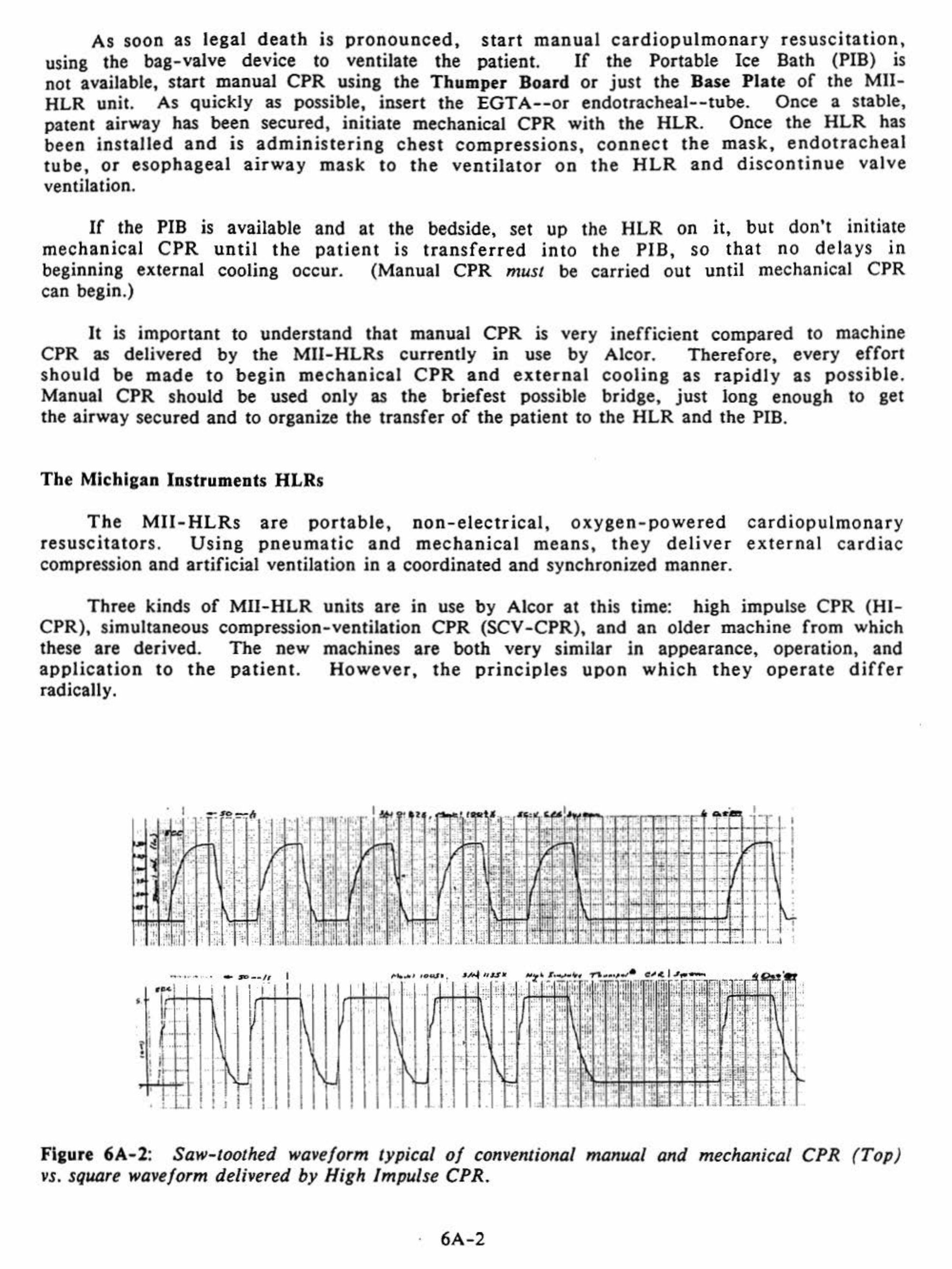
Fi&ure 6A-2: Saw-toothed waveform typical
of
conventional manual
and
mechanical
CPR
(Top
)
vs. square waveform delivered
by
H
igh
Impul
se
CPR.
·
6A-2

HI-CPR
-
The
HI-CPR
unit
(Mll
"Thumper" Cardiopulmonary Resuscitator, Model 1005X)
is
designed to shape the wave
form
of
the impulse delivered to
the
patient's
chest during
cardiac compression.
The
normal
wave delivered
by
manual
or
mechanical
CPR
is
saw-
toothed, and results
in
prolonged high
intrathoracic
pressures.
The
HI-CPR
unit
delivers
a square wave with resulting very high acceleration
of
the chest wall.
The
heart
is thus
"selectively compressed"
by
the shock wave.
HI-CPR
has resulted in cardiac
output
two to
three times greater
than
that
achievable
with
conventional closed chest
CPR
and
without
the prolonged high intrathoracic pressure associated with conventional
CPR.
SCV-CPR
-
The
SCV-CPR
unit
(Mil
"Life Aid" Resuscitator, Model 1004X) works
on
a
completely
different
principle
than
HI-CPR.
SCV
-CPR
uses the
entire
chest
and
the
blood
vessels within
it
as a "thoracic pump".
This
is
achieved by raising the pressure inside
the chest to
very
high levels
during
cardiac compression
by
simultaneously compressing the
chest
and
ventilating the
patient
at very high airway pressures (55 to 95
mm
H20
rather
than the
normal
25 to 30 mm H20 used in ventilation).
The
unit
thus
delivers 80 strokes/respirations
per
minute
and
interposes a pause in
ventilation
for
exhalation
after
each
5th compression.
CAUTION:
SCV-CPR
is
contraindicated
in pulmonary disease where
high
airway
pressures
could
result
in
tension
pneumothorax
(such
as
emphysema,
adult
respiratory
distress
syndrome (ARDS),
patients
with
pre-existing
pneumothorax
from
lung-related
causes,
and
patients
with
long
histories
of
tobacco
abuse
in whom
lung
friability
is suspected).
Primary
or
secondary
carcinoma
of
the
lung
is
a
relative
contraindication:
the
patient's
condition
must
be evaluated by ASC
staff
before proceeding to use
SCV-CPR.
The
MII-HLR
HLRs
operate
on
compressed oxygen. In
other
words,
they
derive the
energy
required
to compress the chest
and
ventilate the lungs
from
a high pressure oxygen
supply. While these systems
free
the
operator
from
dependence
on
electric power,
they
have the
drawback
of
requiring large quantities
of
oxygen.
The
two
standard
"E"
cylinders
(20
cubic
feet,
or
570 liters
each
of
02) which come with the
HLR
in the
Alcor
rescue
kit
will provide approximately
20-30
minutes
of
operation
under
normal
circumstances
(no
more
than
20 minutes when using the SCV
-CPR
machine).
For
this reason,
the
£-cylinders
should
be used only where
other
sources
of
compressed oxygen
are
not
available
for
transport
of
the
patient.
It
is
preferable
to
use
a
hospital-provided
oxygen
supply,
either
in
the
form
of
an
H-cylinder
(220 cubic feet,
or
7100 liters)
or
the wall oxygen
outlet,
and
arrangements should be made
in
advance, wherever possible.
Switchover
from
E-cylinders
to
an
H-cylinder
or
hospital wall oxygen
supply
may be
done without
interruption
of
CPR,
since the
MII-HLRs
have a
buffer
tank
and
a special
Oxygen
Input
Hose which holds a
supply
of
oxygen
sufficient
for
4-7
cycles
of
the
HLR.
This
allows
the
device
to
continue
to
operate
during
the
brief
interval
required
for
switchover.
The
Oxygen
Input
Hose
is
equipped
with a
combination
check
valve/quick
disconnect
on
the
end
to be connected to the oxygen supply.
This
valve
prevents
S0-90 psi
gas
from
escaping
from
the Oxygen
Input
Hose
and
buffer
tank
when
the Oxygen
Input
Hose is
disconnected
from
one source
of
oxygen and
switched
over
to
another.
Regardless
of
whether
hospital
wall
oxygen
or
an
H-cylinder
is
to
be
used,
the
6A-3

Respiratory Therapy Department
of
the hospital must be contacted. Arrangements with them
must be made for
the
presence
of
an
H-cylinder
or
the availability
of
an adapter
or
coupler which will allow the
HLR
to tap into the wall oxygen outlet. In the event a wall
outlet
is
used,
a
regulator
will
be
unnecessary,
since
standard
hospital
delivery
pressure
for medical devices is 50
to
90 psi, the operating pressure required
by
the
HLR.
Wall
adapters
are
manufactured
in
a
variety
of
styles,
using
a
wide
range
of
operating principles. It will be necessary to obtain an adapter for
the
system which is
in use in the particular hospital the patient is in, and to make certain that the adapter
does not have any flow restrictions
or
other
devices attached
to
it
(such
as
an oxygen
flowmeter).
CAUTION:
It
is very important
that
the
check
valve/quick disconnect not be removed
from
the
Oxygen
Input
Hose when connecting
the
MII-HLR
to
wall
or
other
oxygen
sources. Removal
of
the
quick disconnect from
the
hose will allow compressed
gas
to
escape from
the
line and
buffer
tank,
resulting in
an
interruption
of
CPR during
switchover.
Circumstances
Of
Use
Of
The
MII-HLR
There may be some situations where the Pffi is not available
or
cannot be used.
Examples
of
such situations are:
a)
sudden emergency in which the Transport Technician
must travel by air with
the
rescue
kit
and the PIB (which,
due
to size, must
be
sent via
airfreight rather than taken as luggage) does not arrive before the emergency begins;
b)
situations
in
which
the
Coordinator
or
Transport
Technician
is
responding
alone
,
or
is
otherwise
unable
to
physically
transport
the
PIB
to
the
patient
(as
in
cases
of
sudden
local emergencies); c) situations
in
which
the
hospital will not allow
it
to be used,
or
where manpower sufficient
to
allow its use is not available.
In such situations,
it
will be necessary
to
apply the
Mll-HLR
to
the
patient and
to
use ice bags for external cooling. Protocols for use
of
the
MII-HLR
both with the PIB and
without
it
are
presented below:
Application
Of
The
HLR
Without
The
PIB
Where possible,
the
HLR
should be applied to the patient with only two interruptions
in manual resuscitation
of
not more than five seconds each. This requires the presence
of
three people on the rescue team,
or
the availability
of
bystanders (hospital personnel) to
provide some help.
After
the
unit
is
in
operation, only one person is required
to
monitor
its performance and insure an adequate airway.
The
HLR
should never be allowed to operate
without the patient being carefully monitored
and
a/tended
by
at least one knowledgeable
individual.
NOTE: Numbers in parentheses
(#}
refer to numbers which appear on the controls
of
the
MII-HLR.
(They
are the same for both models.) Names
of
HLR
controls in bold face
refer to the diagrams
of
the
Mli-HLR
unit, which appear at the beginnings
of
the
sections
on
the individual units.
6A-4
•
~
•
•
"•
Figure
6A-3
.....
• r I
' c ;
@]
I
1•
0
n·~·••:_c•
~g.6.
!,'
1'
~
CHIIT
R-,
.....
CAIIOIAC
CO.PIItlltO•
WAl'll
-·
..
!
..
..-
¥111TILATO•
WAL¥1!
1}"'-
-
--in
- - -
ItT
OU.ITOLIC
PIRIOD
1 , • -
II!T
Yl:tfTtLATIO•
TWI
-IDIAITOI.IC
,.--,
D
-;.
1.
-'
,n·
CO
..
ftOL
.
I
I I .\
'
I
•
"'
.,
'••...__
Nllii-UIIt
RIL.F
WAL¥1.
\
'\_
YIMTUtlll
~-
'
RIIAD
YI.TK.ATto"
NIIIURI
~
'I
I
L .,.,,.,.,,,
co•THL
w.t.LYE
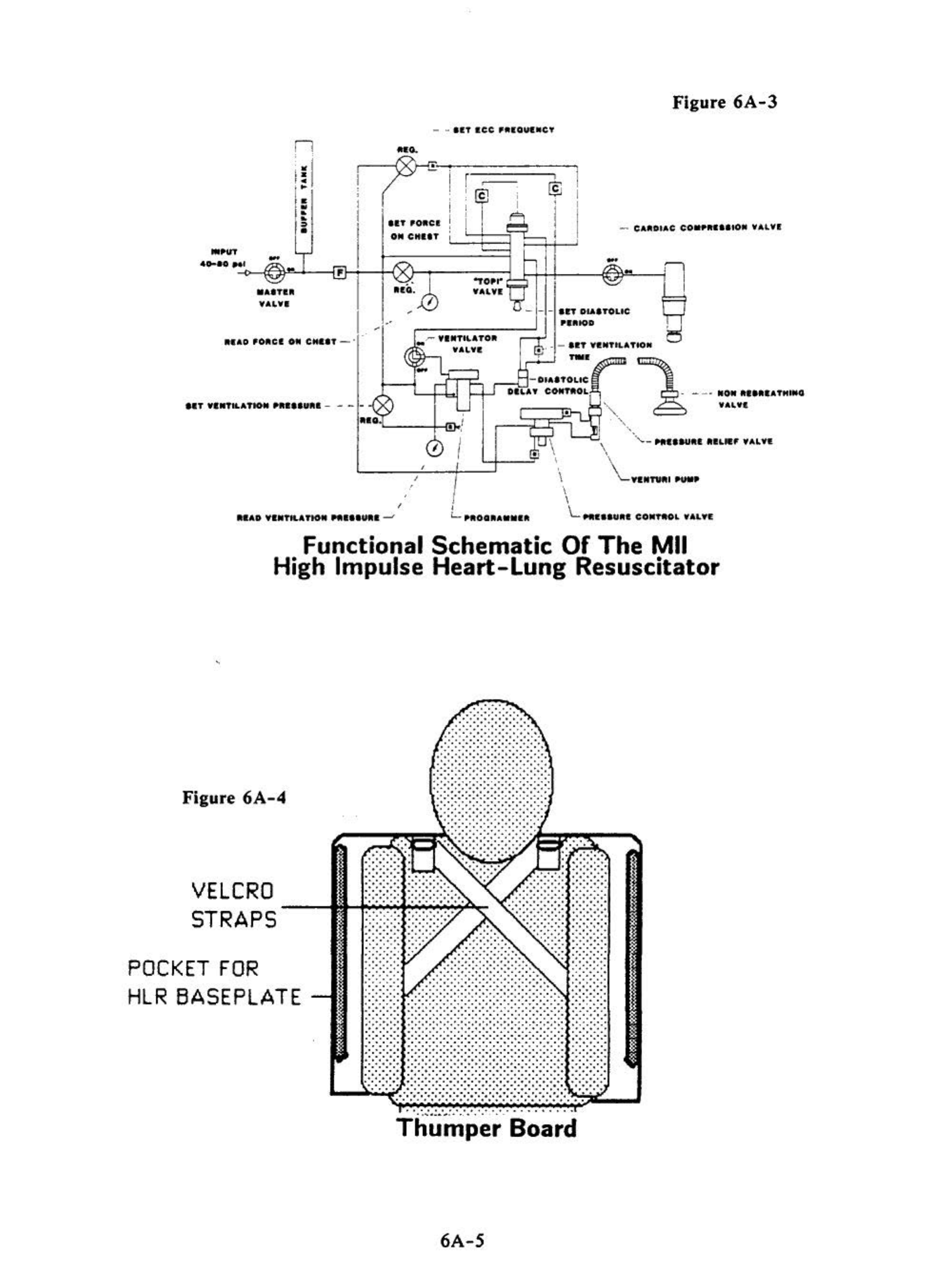
Functional
Schematic
Of
The
Mil
High Impulse
Heart-Lung
Resuscitator
Figure
6A-4
VELCRO
STRAPS
POCKET
FOR
HLR
BASEPLATE
.. .. .
..... .
...
...
......
..
·
...
.
.. .. .
.....
.. .. .
.... .. ....
...
.
......
..
...
..
.
........ .
... .. .. ...
... ..... . .
. ... ......
. . . ... . ..
.. ... ..'
. . . .. ..
....... ..
.... ....
........
.. .... .. .
.........
.........
........
........
.......
.... . . . . .....
.. ....
.....
.... . '
.....
....
..
..............
.......
.....
.....
.....
..
....
·
..
Thumper
Board
6A-5

COLUMN
ARM
ASSEMBL
V
COLUMN
LABEL
(L__-\-_L__J
~
t---
ARM
-------+-~
-
DOME
WITH
LOCKING
KNOB
L,......_:J-----1
MARKING
RINGS
-
--
--
-
PRESSURE
__
___;;;;;=--{
·.
RELIEF
VALVE -
-
-
L..--
MASSAGER PAD
-
-
-
-
-
BREATHING --
-
-
~-
BASE
PLATE
HOSE--_;.-:::
--
=-=GJl---
NON
REBREATHING VALVE
Mil High Impulse
Heart-Lung Resuscitator
Figure 6A-S Side View
MAXIMUM
VENTILATION
PRESSURE
LIMIT
GAUGE
MAXIMUM
VENTILATION
PRESSURE
LIMIT
KNOB
(•5)-
OXYGEN
INLET
MASSAGER
VENTILATION
SWITCH
(•4)
MASTER
PAD
VENTILATOR
OUTLET
CARDIAC
COMPRESSION
VALVE
(•2)-------..,._
--t--t=--1
COLUMN
LABEL
CARRYING
-----l
HANDLE
COLUMN
LATCH _
_..~
VALVE
('1)
ARM
BASE
PLATE
Figure
6A-6
....__
__
ARM
LOCKING
KNOB
Mil High Impulse
Heart-Lung Resuscitator
Top
View
6A-6

TO
HLR
BASEPLAT
E
Fia:ure
6A-7
PRESSURE
RELIEF
VALVE
CONDUCTIVE
HOSE
Mil
Breathing
Hose
Assembly
High
Impulse CPR
Unit
(Mil
"Thumper" Cardiopulmonary Resuscitator)
.....
-
TO
MASK
OR
-+
ENDOTRACHEAL
TUBE
NON
REBREATHING
VALVE
I )
During
an
interruption
in
CPR
of
no
longer
than
five
seco
nd
s,
elevate
the
patient's
head
and
shoulders
(or
roll
the
patient
onto
his
side)
and
slip
the
Thumper
Board
of
the
'device
under
the
patient
with
the
patient's head
extending
over
the
hump
at
the top
of
the
Thumper
Board
(if
the
Thumper
Board has not already been positioned
under
the
patient
prior
to
the
start
of
manual
CPR).
This
extends
the
head
and
facilitates
opening
of
the airway
and
positioning
of
the pat
ient
for
intubat
ion,
if
it
has not been
carried
out
already. Manual cardiac compression
and
ventilation are then resumed.
If
the
Thumper
Board
is
not
available, place
the
base plate
of
the machine
under
the patient
at
the
start
of
manual CPR.
2) Insert the
MII-HLR
Base
Plate
into the
Thumper
Board.
To
accomplish this,
insert the
tip
of
the Base
Plate
into
the flared opening between the two plastic sheets
and push
it
into place until a positive stop is felt
(the
patient
need not be moved
or
lifted to accomplish this). (Figure
6A-8.)
Figure
6A-8
Figure
6A-9
6A-7

3)
Remove the Arm/Column Assembly
from
th
e storage case.
Holding
th
e column as
shown in Figure
6A-9
(with the
Cardiac
Compression Valve
(#2)
toward
the rescuer), loosen
the Arm
Lockln~
Knob and
sw
ing t
he
ar
m 90°
on
the
column
towards
the
patient's
feet
, then
tighten
th
e Arm
Lockin~
Knob slightly.
..,
•
-
, .
'i
•
Figure
6A-10
Figure
6A-11
4)
Atta
ch the Arm
/C
olumn Assembly to
the
base plate
of
the
HLR,
as shown
in
Figure
6A
-10. A
ccomp
lish this
by
tipping
the
column
slightly
forward,
slipping the "toe"
of
the
column base
in
to
its slot,
then
pulling the
column
back
sharply
until
it
is latched.
5)
Co
nn
ec
t
the
Pressure
Relief
Valve
(l
arge
green
fitting)
on
the
end
of
the
Breathin&
Hose
to the
Ventilator
Outlet
per
Figure
6A-l
1.
Be sure
that
the
end-tidal
C0
2
detector
has
been
installed
on
the
patient
end
of
the
breathing
hose
if
it
ha
s
not
been
previously
installed
between
the
EGT
A
(or
endotracheal
tube)
and
the
bag
-valve
resuscitator.
•
Fieure
6A-12
Figure
6A-13
6A-8
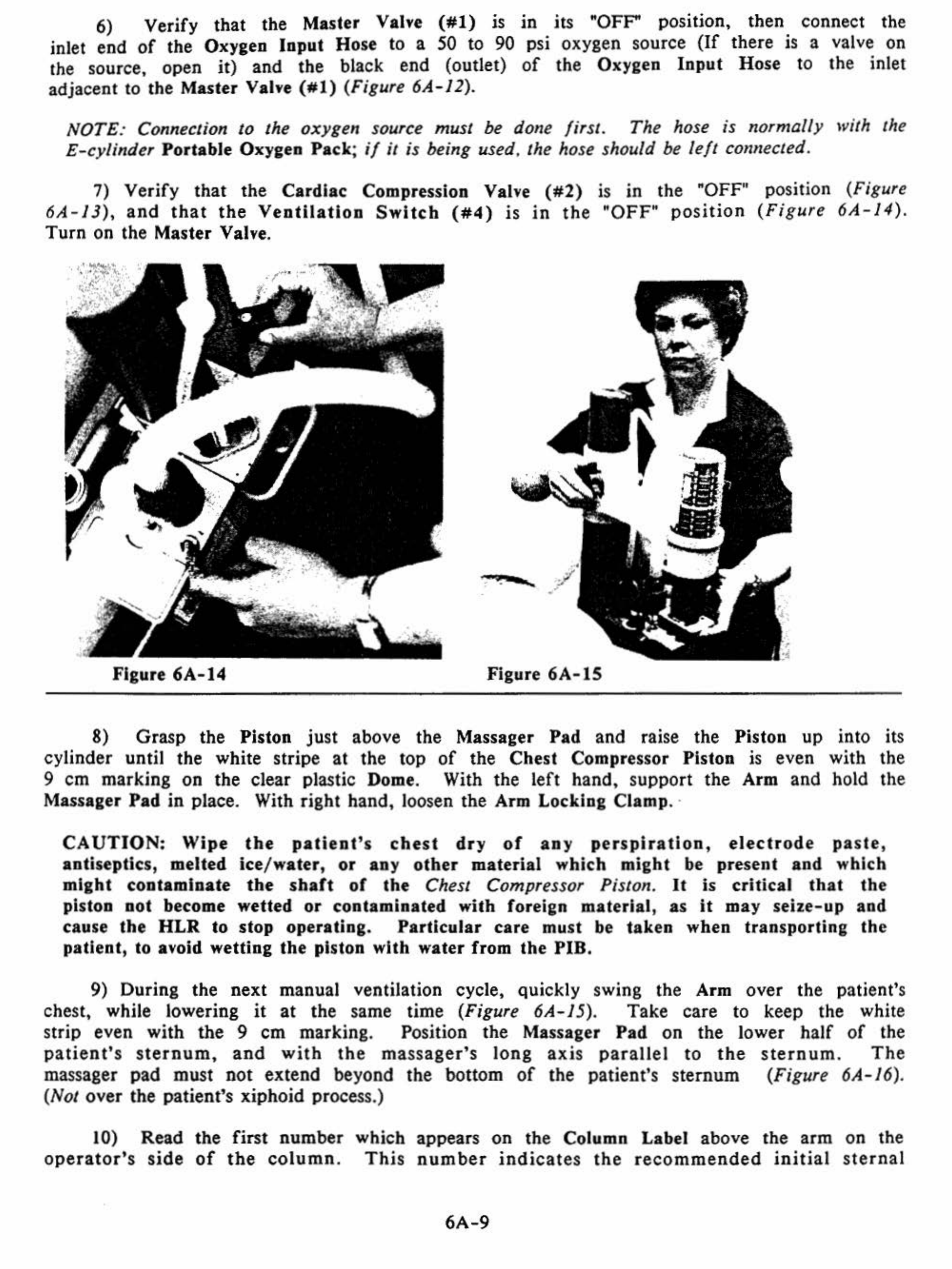
6) Verify that the Mas
ter
Valve
(#1)
is
in
it
s
"OFF'
position, then connect the
inlet end of the Oxygen
Input
Hose to a 50 to 90 psi oxygen source (
If
there is a valve on
the source, open it) and
the
black end (outlet)
of
th
e Oxygen
Input
Hose to the inlet
adjacent to the Master Valve
(#1)
(Figure
6A-J
2).
NOTE: Connection to the oxygen source must be done first. The hose is normally with the
£-cylinder Portable Oxygen
Pack
; if
it
is being used, the hose should be
left
connected.
7) Ve
rify
that
the
Cardiac Compression Valve
(#2)
is in the "OFF" position (Figure
6A-13),
and
that
the
Ventilation
Switch
(#4)
is
in
the "OFF"
position
(Fig
ure
6A-14).
Turn on the Master Valve.
' Q ;
' .
Figure 6A-14 Figure
6A-15
8) Grasp the Piston
ju
st above the Massager Pad and raise the Piston up into
it
s
cylinder until the white stripe
at
the top of
the
Chest Compressor Piston
is
even with the
9
em
marking on
the
clear pl
as
tic Dome. With
th
e
left
hand, suppo
rt
the Arm and hold the
Massager
Pad
in
place. With rig
ht
hand, loosen
the
Arm Locking Clamp. ·
CAUTION:
Wipe
the
patient's
chest
dry
of
any
perspiration,
electrode
pa
s
te
,
antiseptic
s,
melted ice/water,
or
any
other
material which might be present
and
which
might contaminate
the
shaft
of
the
Chest Compressor Piston.
It
is critical
that
the
piston not become wetted
or
contaminated with foreian material,
as
it
may seize-up and
cause
the
HLR
to stop operating.
Particular
care must
be
taken when transporting
the
patient, to avoid wetting
the
piston with water from
the
PIB.
9) During the next manual ventilation cycle, qui
ck
ly swing the Arm
over
the
patient's
chest, while lowering
it
at
th
e same time (Figure 6A- 15). Take care to keep the white
str
ip
even with
the
9
em
mark
ing. Position the Massager
Pad
on the lower half
of
the
pat
ient'
s s
ternum
,
and
with
the
ma
ssage
r's
long
axis
parall
el
to
the
s
tern
um.
Th
e
massager pad must n
ot
extend beyond
the
bottom
of
the patient's sternum (Figure 6A-16).
(Not over
th
e patient's xiphoid process.)
10) Read the first number
operator's
side
of
the
column
. which
Thi
s appears on the Column Label above
th
e arm on the
number
indi
c
at
es
the
recommended
initial
ste
r
nal
6A-9

Figure
6A-16
Figure
6A-17
deflection
setting
,
and
corresponds
to
20%
of
the
patient's
anterior-posterior
(AP)
diameter.
Caution!
The
top is
numbered
from
6
on
top to 3 on the bottom.
The
line below 5 JS
4
1/2,
not
5
1/2.
II)
Raise the Arm back
up
the column until the white stripe at the top
of
the
Chest
Compressor Piston is
at
the
numbered
marking corresponding
with
the
number
read from the
Column Label in Step
10.
(If
the
arm
is between two numbers,
adjust
the Compressor Piston
accordingly.) Lock the Arm into place.
12)
Turn
on
the
Cardiac
Compression Valve. This will initiate chest compressions.
Steps 8 through
12
should be repeatedly practiced so
that
the time required to set
chest
compressor
deflection
does
not
result
in
more
than
a
five
second
interruption
in
CPR.
13)
At
the same time as steps
9-12,
the
Technician
in charge
of
respirations should
attach the
End-
Tidal
C0
2 Detector above
the
endotracheal
tube
or
EGT
A.
14) Verify
that
the maximum ventilation setting is
at
the
normal
pre-setting
of
25-
30
em
of
H2
0.
This maximum pressure limit setting is read continuously·
on
the Maximum
Ventilation Pressure
Limit
Gauge once the
Master
Valve is
turned
on.
If
incorrect,
it
can
be
adjusted
by
rotating
the
Maximum
Ventilation
Pressure
Limit
Control
Knob
(#S)
(clockwise
to
increase,
counterclockwise
to
reduce).
When
the
ventilator
pressure
has
been so set, attach the
end
of
the
Breathing
Hose to the
End-Tidal
C0
2 Detector,
and
turn
the Ventilation
Switch
(#4)
to the
"ON"
position
(Figure
6A-18)
.
15)
The
carotid
arterial
pulse should
be
evaluated
and
verified
as present with each
chest
compression.
A
chest
rise
of
0.6
to
1.9
em,
dependent
upon
patient
size
and
measured
by
piston motion within the Dome, should be visible with
each
ventilation cycle.
End
tidal
C0
2 concentration should be
no
less
than
3%.
(If
it
is below 3%. something is
seriously
wrong.
See
Chapter
5,
Cardiopumonary
Support:
Evaluation
And
Intervention,
especially page
5-5,
for
possible corrective actions.)
6A-10

16)
The
Transport Technician should continue to monitor the unit
for
pr
oper equipment
function and
proper
settings,
and
mon
itor
the patie
nt
for palpable pulse, adequate chest
rise
during
v
entilation
, a
nd
adequate
end-tid
al
CO~.
If
th
e
pul
se is
weak
or
undetectable, ste
rn
al defl
ect
ion can be
in
creased
by
lowenng
the
co
lumn h
eight
.
If
chest
ri
se
is inadequate,
the
maximum ventilation pressure limit should
be
incr
eased
by
tur
ning
the Maximum Ventilation
Pressur
e Limit
Control
Knob
(#5)
clockwise to increase
th
e lim
it
pressure.
r.vl':,•r
.:
0
·78
p111
HJ.$1£P
VA
l.\'
£
SCT
roi!Ct
ON
CH£ST-
-
_J
ON
-
~·
Vt
.
'V1'
lL.A
TOFi
~
'
A
!.\
'
!'·-'·
·
OH
Fieure
6A-18
r·C
A
ROI
AC
/ COI<PR£SS
lON
·' V,tiLVC
r----
-11
r St:'T
DI
A
STOLIC
P£11100
V St:'T Vt:II
TIU.T
!O
N
/
_.,-
-Tli<E
DIASTOLI
C'
l
~=f~ctS
otu.r
C'ONTROL
PRESSVRt:
CONTROL
VALVl'.
.• /
.'G'
L-
__.
·
-~f----
'--
PRESSVI!t:
VA
LV
F.
·VC.
\'
TURI
PU
HP
I!CAD
C::::l-
• ·
NON
R£8/IEATH
INC
\.'
AZ,.V!,'
-
..11£/J'T
li..ATlON
PR£SSURC
L--
$!
'1
VCN':I
UTIO:~
PRt:SSUR£
Functional
Schematic
Of
The
Mil
Simultaneous
Compression
-Ventilation
Heart
-
lung
Resu
sci
tator
Figure
6A-19
6A-11
NOTE:
If
the
patient
is
intubated,
increased
ai
rway
resis
t
ance
imposed
by
the
endotracheal tube
may
require a higher
maximum
airway
pressure
in
order to achieve
adequate
chest
rise
.
With
the
proper
installation
of
a
cuffed
endotracheal
tube,
limiting ventilation pressure
may
be
increased as needed, up to 60
em
of
H2o.
NOTE
:
After
an
hour
of
CPR,
it
is
likely
that
the
patient's
chest
will
become
flattened
from
the
sternal
compressions.
In
order
to
maintain
adequate
compression
depth,
it
will
be
necessary to lower the plunger
fu
rther,
by
remeasuring with steps
8-
12 above.
CAUTION:
At
least
one
operator
must
continue
to
monitor
the
operation
of
the
HLR
and
the
responses
of
the
patient
at
all
times while
the
unit is in use.
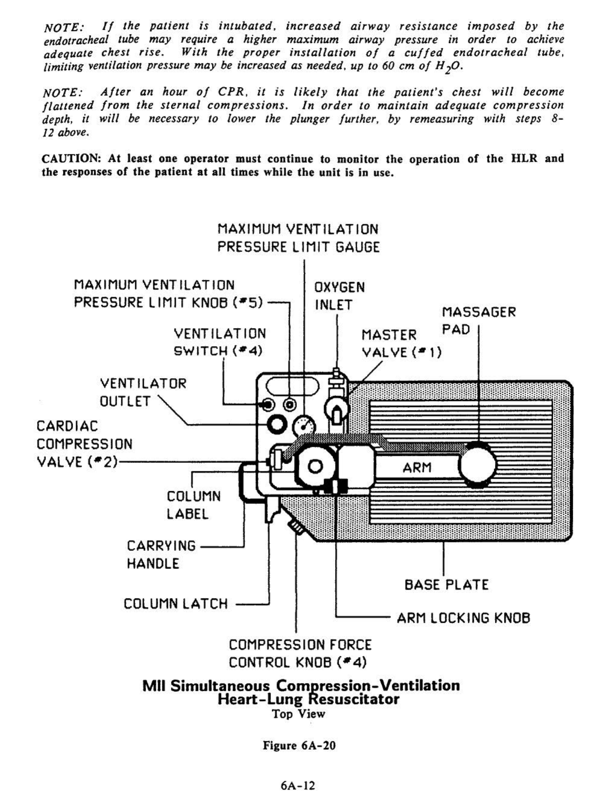
MAXIMUM
VENTILATION
PRESSURE
LIMIT
GAUGE
MAXIMUM
VENTILATION
PRESSURE
LIMIT KN06
(•5)----.
VENTILATION
SWITCH
(•4)
VENTILATOR
OUTLET
CARDIAC
COMPRESSION
VALVE (•
2)------;:=~f:l:~
=--11
COLUMN
LA6EL
CARRVING
----J
HANDLE
OXVGEN
INLET
MASTER
VALVE
(•t)
ARM
MASSAGER
PAD
6ASE PLATE
COLUMN
LATCH
....___
__
ARM
LOCKING
KNOB
COMPRESSION
FORCE
CONTROL
KNOB
(•4)
Mil
Simultaneous Compression-Ventilation
Heart-lung
Resuscitator
Top View
'
Figure
6A-20
6A-12
COLUMN
ARM
ASSEMBLV
COLUMN
L
ABE
L·
irt---\.---L--4-
ARM
LOCKING
-----4----'•
KNOB
_
l.-~--~
~--CHEST
COMPRESSOR
PISTON
WITH MARKING RINGS
--
-
-
-
PRESSURE
--__,;:;;--f:
-
-
RELIEFVALVE =
L..--
MASSAGER PAD
-
-
-
-
-
-
--BASE
PLATE
BREATHING
HOSE------
-=-==~~NON
REBREATHING VALVE
Figure
6A-21
Mil
Simultaneous Com_pression-Ventilation
Heart-Lung Resuscitator
Side View
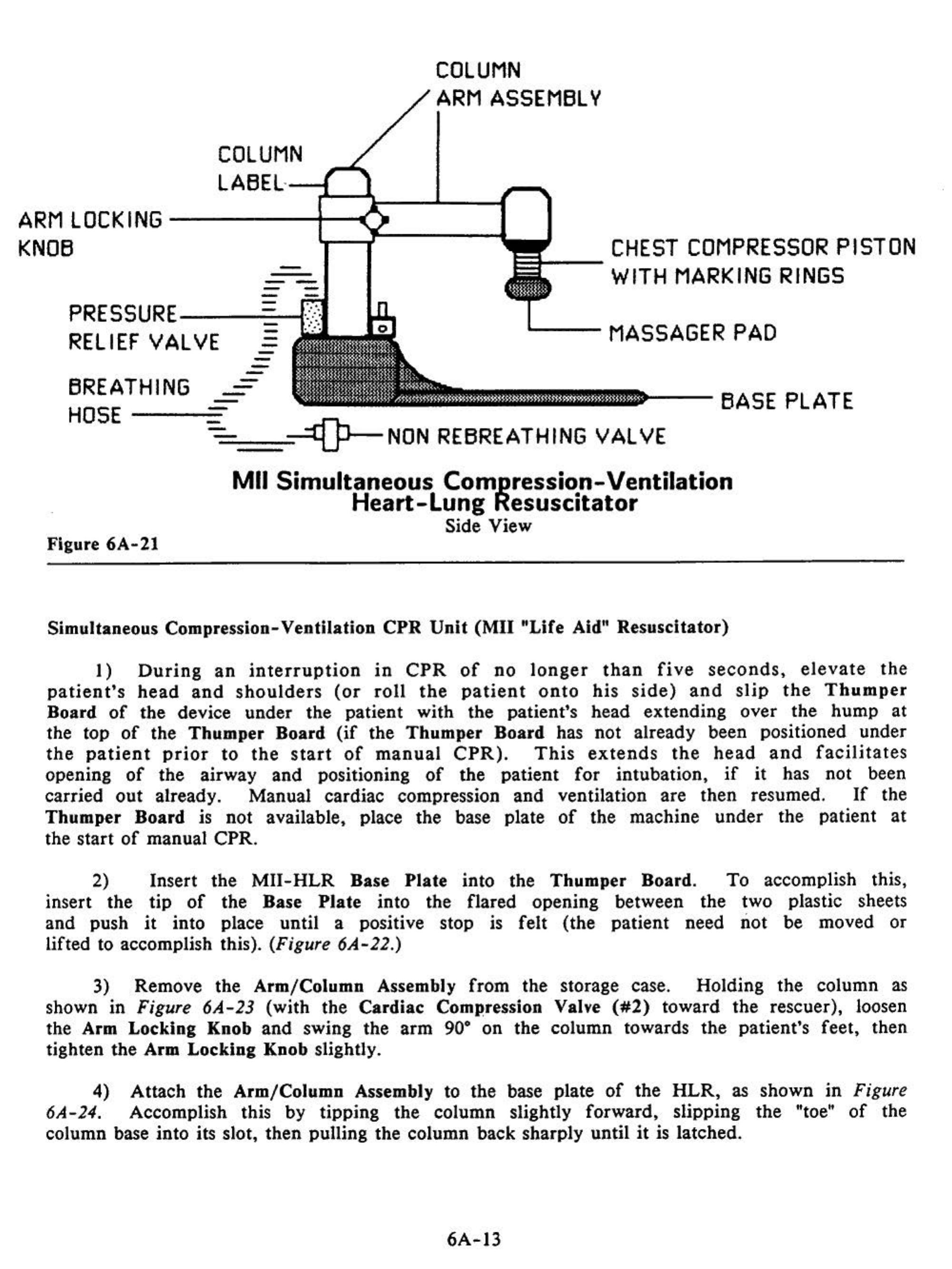
Simultaneous Compression-
Ventilation
CPR
Unit
(Mil
"Life
Aid"
Resuscitator)
I)
During
an
interruption
in
CPR
of
no
longer
than
five
seconds,
elevate
the
patient's
head
and
shoulders
(or
roll
the
patient
onto
his
side)
and
slip
the
Thumper
Board
of
the
device
under
the
patient
with
the
patient's
head
extending
over
the
hump
at
the
top
of
the
Thumper
Board
(if
the
Thumper
Board
has
not
already
been
positioned
under
the
patient
prior
to
the
start
of
manual
CPR).
This
extends
the
head
and
facilitates
opening
of
the
airway
and
positioning
of
the
patient
for
intubation,
if
it
has
not
been
carried
out
already. Manual
cardiac
compression
and
ventilation
are
then
resumed.
If
the
Thumper
Board
is
not
available, place
the
base plate
of
the
machine
under
the
patient
at
the
start
of
manual
CPR
.
2) Insert
the
MII-HLR
Base
Plate
into
the
Thumper
Board.
To
accomplish this,
insert
the
tip
of
the
Base
Plate
into
the
flared
opening
between
the
two plastic sheets
and
push
it
into place
until
a positive stop
is
felt (the
patient
need
not
be moved
or
lifted to accomplish this).
(Figure
6A-22.)
3)
Remove
the
Arm/Column
Assembly
from
the
storage case.
Holding
the
column
as
shown
in
Figure
6A-23
(with
the
Cardiac
Compression Valve
(#2)
toward
the
rescuer), loosen
the Arm
Locking
Knob
and
swing
the
arm
90"
on
the
column
towards
the
patient's
feet,
then
tighten
the
Arm
Locking
Knob slightly.
4)
Attach
the
Arm/Column
Assembly to
the
base plate
of
the
HLR,
as
shown
in
Figure
6A-24. Accomplish this by
tipping
the
column
slightly
forward,
slipping
the
"toe"
of
the
column
base
into
its slot,
then
pulling
the
column
back
sharply
until
it
is latched.
6A-13

Figure
6A-22
,
\j
·
Figure
6A-24
---
•
Figure
6A-23
Figure
6A-25
••
"'
5)
Connect
the
Pressure
Relief
Valve
(
larg
e
green
fitting)
on
the
end
of
the
Br
eat
hing Hose to the
Ventilator
Outlet
per
Figure 6A-25.
6)
Verify
that
the Master Valve
(#I)
is
in
its "OFF" position,
that
the Cardiac
Compression Valve
(#2)
is "OFF",
that
the Ventilation
Switch
(#4)
is
"OFF',
and
that
the
Compression Force Control Knob
(#3)
is
off
(fully counterclockwise).
Then
connect the
inlet
end
of
the Oxygen
Input
Hose to a 50 to 90 psi oxygen source (If the source has a
valve,
turn
it
on)
and
the
black
end
(o
utlet)
of
the
Oxygen
Input
Hose
to
the
inlet
adjacent
to the Master Valve
(#I)
(Figure 6A-26).
6A-14

Figure
6A-26
Figure
6A-27
NOTE: Connection to the oxygen source must
be
done first. The hose is normally with
the
E-cylinder
Portable
Oxygen
Pack;
if
it
is
being
used
,
the
hose
should
be
left
connected.
7)
Grasp
the
Piston
just
above the Massager
Pad
cylinder until the bottom marking ring
in
the piston is
cylinder. With the
left
hand,
support
the Arm
and
hold
right hand, loosen the Arm Locking Clamp.
and
raise
the
Piston
up
into
its
just
about
to
disappear
into the
the Massager
Pad
in
place. With
CAUTION:
Wipe
the
patient's
chest
dry
of
any
perspiration,
electrode
paste,
antiseptics,
melted
ice/water,
or
any
other
material
present which
might
contaminate
the
shaft
of
the
Chest Compressor Piston.
It
is
critical
that
the
piston
not
become
wetted
or
contaminated
with foreign
material,
as
it
may
seize-up
and
cause
the
HLR
to
stop operating.
Particular
care
must be
taken
when
transporting
the
patient
to
avoid
wettlng
the
piston with
water
from
the
PIB
.
I
'
.•..
:.
. .
.··.
Figure
6A-28
/
~
··
~~
·
r\
•
6A-15
·.
•
< ..
--
··
-~
·
·- .
~
.
_,f
, . .
'<
·.:·
.
·:
c;·
.
•
Ci
• • • .
"'<
~.
~.,
....
·-
..
. .

8) During the next manual ventilation cycle, quickly swing the Arm over
the
patient's
chest, while lowering
it
at
the same time (Figure
6A-27).
Take care to keep the bottom
marking ring just visible. Position
the
Massager Pad on the lower
half
of
the
patient's
sternum, and with the massager's long axis parallel to the sternum.
The
massager pad must
not extend beyond the bottom
of
the patient's sternum
(Figure
6A-
28). (Not over the
patient's xiphoid process.) Lock arm
in
place.
Figure
6A-29
Figure
6A-30
6A-16
9)
Turn
the Master Valve
(#l)
"ON",
and
confirm
that the force
on
the Compres.sor
Force Gauge
is
zero; then
turn
the
Cardiac
Compression Valve
(#2)
to "ON" (Figure 6A-31).
The
ventilator will begin to cycle with each compression once
the
Master Valve is
turned on.
10) Adult Setting: Gradually
turn
the Compression Force
Control
Knob
(#3)
(Figure 6A-
30) clockwise until the piston depresses the
sternum
20-25%
of
the chest
A-P
diameter.
With
full-grown
adults, displacement should be approximately
It"
to
2".
In
general,
this will
occur
when the Compressor Force
Gauge
("Force
On
Chest")
indicates 60 to 80
pounds
of
force.
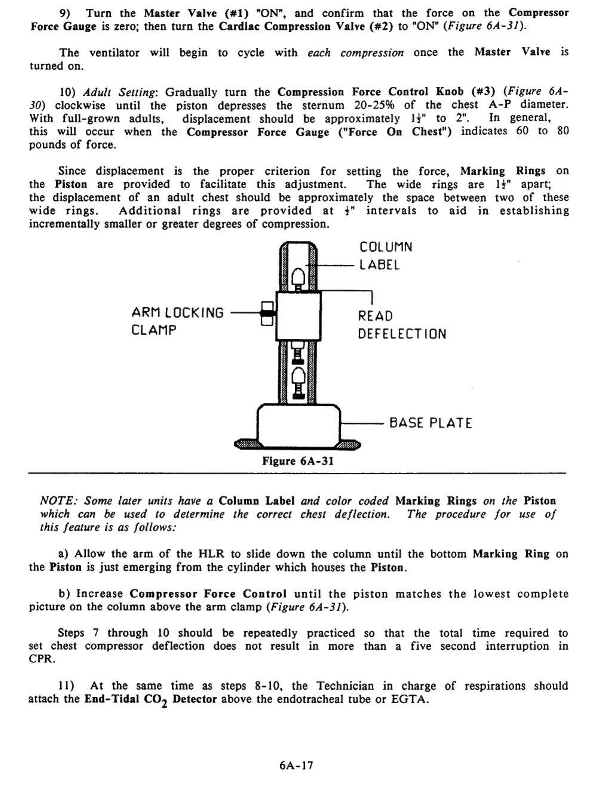
Since displacement is
the
proper
criterion
for
setting the force, Marking Rings
on
the Piston are provided to facilitate this adjustment.
The
wide rings are
It"
apart;
the displacement
of
an
adult
chest should be approximately
the
space between two
of
these
wide
rings.
Additional
rings
are
provided
at
t"
intervals
to
aid
in
establishing
incrementally smaller
or
greater degrees
of
compression.
ARM LOCKING
CLAMP
COLUMN
--LABEL
READ
DEFELECT
ION
t---
BASE PLATE
Figure
6A-31
NOTE: Some later units have a Column Label and color coded Marking Rings on the Piston
which can
be
used
to
determine the correct chest deflection. The procedure for use
of
this feature is as follows:
a) Allow the
arm
of
the
HLR
to slide down the column until
the
bottom Marking Ring on
the Piston is
just
emerging
from
the cylinder which houses the Piston.
b)
Increase
Compressor
Force
Control
until
the
piston
matches
the
lowest
complete
picture on the column above the
arm
clamp (Figure 6A-31).
Steps 7 through 10 should be repeatedly
set chest compressor deflection does not result
CPR.
practiced
.
m more so
that
the
than
a five total time required to
second interruption in
II)
At
the same time as steps
8-10,
the Technician
in
charge
of
respirations should
attach the
End-Tidal
C0
2 Detector above the endotracheal tube
or
EGTA.
6A-17

..
,
'
.
.·
Figure
6A-32
12)
Verify
that
the
maximum ventilation se
tting
is
at
the
normal
pre-set
ting
of
60
em
of
H2
0.
This
maximum
pressure
limit
setting is
read
continuously on
the
Ventilation
Pressure Gauge
once
the
Master Valve is
turned
on.
If
incorrect,
it
can
be
adjusted
by
rotating
the
Ventilation
Pressure
Control
Knob
(
#5)
(clockwise
to
increase
,
counterclockwise to reduce). When
the
ventilator pressure has
been
so set,
attach
the
end
of
the
breathing
hose
to
the
endotracheal
tube
or
EGTA
and
turn
the
Ventilation
Switch
(#4)
to
the
"ON" position (Figure
6A-32)
.
13) Carotid
arterial
pulse should be evaluated
and
be
determined
to
be
present
with
each
chest
compression.
End
tidal co2
concentration
should
be
no
less
than
3%.
(If
it
is
below
3%,
something
is
seriously
wrong.
·
See
Chapter
5,
Cardiopulmonary
Support:
Evaluation And
Intervention,
especially
page
5-5,
for
possible corrective actions.)
14)
The
Transport
Technician
should
continue
to
monitor
the
unit
for
proper
equipment
function
and
proper
settings, and monitor
the
patient
for
palpable pulse,
adequate
chest
rise
during
ventilation,
and
adequate
end-tidal
C0
2.
If
the
pulse
is
weak
or
undetectable,
sternal
deflection
can
be
increased
by
lowering
the
column
height.
If
cardiac
output
is still
deemed
to be
inadequate
,
the
maximum
ventilation pressure limit
should be increased
by
turning
the
Ventilation
Pressure
Control
Knob
(#5)
clockwise to
increase
the
limit
pressure to
95
em
H20 (the
unmarked
upper
limit
of
the
red zone on the
gauge).
NOTE
:
After
an
hour
of
CPR,
it
is
likely
that
the
patient
's
chest
will
be
c
ome
flattened
from
the
sternal
compressions.
In
order
to
maintain
adequate
compression
depth,
it
will
be necessary to lower the plunger further,
by
remeasuring with steps
7-
10
above.
CAUTION: At
least
one
operator
must
continue
to
monitor
the
operation
of
the
HLR
and
the
responses
of
the
patient
at
all
times while
the
unit
is
in
use.
6A-18

Application
Of
The
MII-HLRs
With
the
PIB
The
procedure
for
application
of
the
MII-HLRs
using
the
PIB
differs
from
the
preceding protocols in the following ways (this presumes the PIB is
already
assembled):
1. Have
the
Backboard
in place
before
the
pat
i
ent
is
put
into the PIB.
2)
Slide the
Base
Plate
into the
cutout
provided in
the
side
of
the
Portable
Ice
Bath
(also
before
the
patient
is
put
into
the
bath,
if
possibl
e.)
3)
Attach the Column Arm to the Base
Plate
of
the
MII-HLR
per the preceding
instructions.
4)
Loosen the Arm Locking
Clamp
and
swing the Arm 90" away
from
the baseplate.
5)
Position the
MII-HLR
in
the PIB
frame
underneath
the
tank
so
that
the Piston will
not
be
too
far
up
on
the
patient's
chest
when
he is placed in the PIB.
.
6)
Connect the
Breathing
Hose
and
the Oxygen Supply Hose
per
instructions
above
.
7)
Interrupt
manual
CPR
and
lift/lower
the patient into the PIB.
The
patient will
probably have to be positioned as close to the Head
of
the PIB as possible.
8)
Grasp
the Piston
just
above the Massager
Pad
and
raise
it
up
into
its cylinder.
Holding
it
there,
loosen
the
Arm Locking Clamp
and
swing the
arm
over
towards the
patient's chest, while lowering it
at
the same time.
CVLINDER
PRESSURE
GAUGE
CARRVING
HANDLE
------CVLINDER
VALVE
~t-
--"T"-HANDLE
REGULATOR
-t---
TWO
WAV
SHUT-OFF--+--
t---
E
CVL
INDER
CONNECTOR
OXVGEN
INPUT~
LINE
---t--CARRVING
HANDLE
---SUPPORTS
Portable
Oxygen
Pack
Figure
6A-33
6A-19
Follow the rest
of
the
appropriate protocol (above) to install the
MII-HLR
and begin
mechanical CPR.
9)
If
possible, start external cooling
of
the patient by packing him
in
crushed ice
at
the
same time that application
of
the
HLR
is
being undertaken.
Be
sure not to place
any ice in
the
PIB be/ore placing the patient in it,
as
this will make proper application
of
the
HLR
impossible.
10) Stow the Portable Oxygen
Pack
on the PIB
and
transfer any IV bottles
to
the PIB ·
IV
pole.
The
patient
can
now be transported from the home, hospital,
or
nursing home.
Input Oxygen Pressure
When
used
with
the
portable
Oxygen
Pack
containing
two
£-cylinders,
the
oxygen
pressure
delivered
to
the
unit
is
preset
at
90
psi.
When
using
an
alternate
oxygen
source, such as hospital wall oxygen
or
a larger oxygen cylinder
and
regulator, the
input
pressure must be
in
the 50 to 90 psi range. This pressure assures delivery
of
up to
95
em
H20 pressure during ventilation
and
at least
125
pounds
of
compressor thrust.
If
the
pressure in
the
tanks falls below 40 psi,
the
maximum compressor thrust may decrease to
below
100
pounds
per
compression and may result
in
inadequate sternal excursion in larger
individuals.
If
the pressure drops further, the compression rate will decrease and the
unit will eventually fail to cycle. Thus,
it
is
imperative that a minimum input pressure
of
at
least
40
psi
be
maintained
at
the
oxygen
source
for
effective,
uninterrupted
resuscitation.
NOTE: The High Impulse
HLR
is very sensltlve to the
oxygen
input pressure. A higher
"specific impulse"
and
thus more
efficient
CPR can be achieved
by
operating the unit
at the high
end
of
the
50-90
psi range (i.e., at 90 psi).
CAUTION: Do
not
connect
the
HLR
to
any
oxygen source with a pressure
greater
than
110
psi,
or
the
unit
may be seriously damaged
and
promptly rendered inoperative.
Portable Oxygen Pack
The Portable Oxygen
Pack
is designed to hold two "E" sized oxygen cylinders, each
of
which
contains
approximately
570
liters
of
oxygen
(at
I
atm.,
70.F)
.
In
typical
adult
use, this will power
the
HLR
for
about 30 minutes (perhaps
as
much
as
10
MINUTES
LESS
for
the SCV
-CPR
unit).
The
Portable Oxygen
Pack
features a
pre-set
and locked regulator which
reduces
the
E-cylinder
pressure from 2300 psi and delivers
it
to
the
Oxygen
Input
Line at
90
psi,
±5%.
A check valve is included in each cylinder circuit, making
it
possible
to
remove and replace an
empty
cylinder while using oxygen from another cylinder.
Quick "in-and-out" cylinder exchange can be carried
out
with the Portable Oxygen
Pack
in either the horizontal
or
vertical position.
Additional cylinder sealing washers are stored in the middle orange
drawer
of
the
Emergency Medications Kit (Gray Box).
CAUTION: While oxygen
Is
Itself a non-flammable gas, It
can
greatly accelerate
the
rate
of
combustion
or
the
likelihood
of
ignition
of
other
materials.
Dramatically
increased rates
of
burning and burning
of
materials not normally
thought
of
as
being
6A-20
Table of contents
Other Michigan Instruments Medical Equipment manuals


