MICRO-AIR OM600 User manual

This manual contains specific cautionary statements relative to worker safety. Read this manual thoroughly and follow
as directed. It is impossible to list all of the hazards of dust control equipment. It is important that use of the equipment be
discussed with a Micro-Air Representative. Persons involved with the equipment or systems should be instructed how to
operate in a safe manner.
OM600
Installation and Operation Manual
MICRO AIR
www.microaironline.com

2
OM600 MICRO AIR
WARNINGS:
CAUTION: Installation can cause exposure to live components. Disconnect electrical power
before proceeding with installation. Proper Lock Out / Tag Out procedures should be used.
All electrical work must be done by a qualified electrician according to local, state and
national codes.
Improper installation or operation of this equipment can cause damage to equipment and / or
injury to personnel. The installation / operation manual must be read and followed in its
entirety.
OM600 SPECIFICATIONS:
Motor: 3/4 HP, 3450 RPM, 1 Phase, TEFC
3/4 HP, 3450 RPM, 3 Phase, TEFC
Input Voltage: 1 Phase - 115/208-230V, 60 Hz
3 Phase - 208-230/460V, 60 Hz
Max Current: 1 Phase - 10.0/5.2-5.0 Amps
3 Phase - 2.5-2.4/1.2 Amps
Blower: Direct Drive
Air Flow: 600 CFM
Dimensions: 40” H x 24” W x 18” D w/ standard legs & standard exhaust
58” H x 24” W x 18” D w/ long legs & HEPA exhaust
Noise Level: 72 dB at 5’ away from unit
Shipping Weight: 180 lbs.
Actual Weight: 120 lbs.
PRE-OPERATING INSTRUCTIONS:
1. Inspect the unit for any visible damage that may have occurred during shipment. Report any
damage to the delivery carrier.
2. Remove the shipping crate, shipping straps and plastic wrap from unit.
3. Remove the unit from the shipping skid and set on a level surface. Note that the legs are not
installed from the factory.
4. Determine the location where the unit is to be installed. Be sure to allow sufficient access to the
unit for servicing and maintenance on all sides.
NOTE: The following instructions will vary depending on options ordered.
EQUIPMENT / TOOLS REQUIRED:
Forklift or Hoist
Lifting straps or chains
Socket wrenches
Wire nuts
Pipe wrench

3
OM600 MICRO AIR
INSTALLATION INSTRUCTIONS:
MACHINE MOUNT / FLOOR MOUNT:
1. Locate an installation site that will provide the following:
a. A solid structure capable of supporting the weight of the unit.
b. 3 ft of unobstructed exhaust space from the outlet of the unit.
c. Easy access to service panels and unit inlet.
d. A close location to the source of the oil mist unit to be captured.
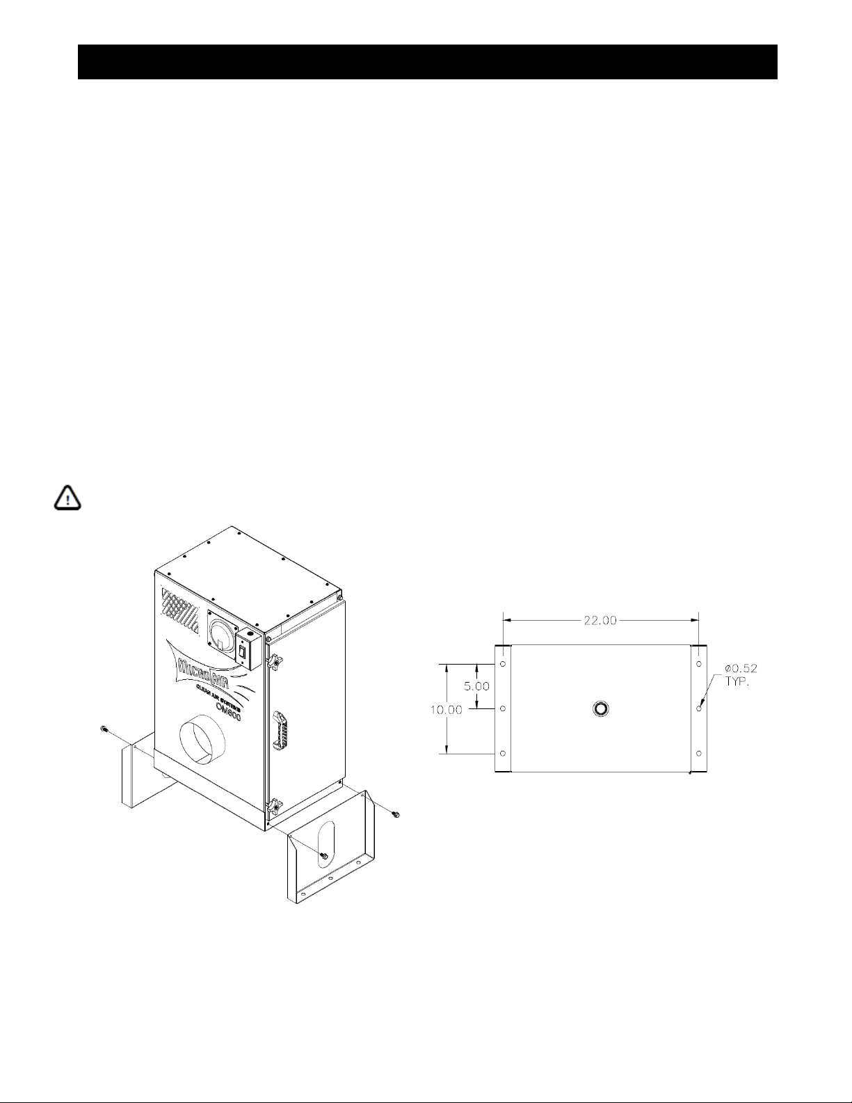
2. Remove the two 5/16-18 bolts from each side of the cabinet on the bottom side of the unit to
secure legs in place. Mount legs to cabinet using removed bolts (FIG. 1).
3. Mark location of the mounting holes on the surface where the OM600 is to be mounted. Note
hole pattern on bottom of cabinet (FIG. 2). Drill holes for a minimum of 3/8” mounting hardware.
4. Secure cabinet to machine using bolts, nuts and lock washers. If machine is mounted on the
floor, use concrete anchors. NOTE: Mounting hardware is not supplied by Micro Air.
5. Connect unit to oil mist source using 6” diameter duct. The duct may be flexible hose or formed
sheet metal. Maximum flow will be achieved with minimum bends in ductwork. The duct must be
sealed to contain oil that will get captured inside it. Use hose clamps or sheet metal screws to
attach duct to unit.
NOTE: There are 2 different set of legs, standard height, 10” tall, or long leg, 16” tall.
CAUTION: The size and weight of the OM600 unit requires two people or mechanical means
to lift and hold in place during mounting.
FIG. 1 FIG. 2

4
OM600 MICRO AIR
CEILING MOUNT:
1. Locate an installation site that will provide the following:
a. A solid structure capable of supporting the weight of the unit.
b. 3 ft of unobstructed exhaust space from the outlet of the unit.
c. Easy access to service panels and unit inlet.
d. A close location to the source of the oil mist unit to be captured.
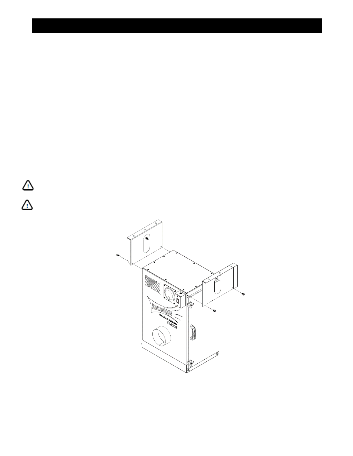
2. Remove the two 5/16-18 bolts from each side of the cabinet on the top side of the unit to secure
legs in place. Mount legs to cabinet using removed bolts (FIG. 3).
3. Firmly secure unit to 4 piece. Note hole pattern on bottom of legs (FIG. 2). Make sure unit is level
NOTE: Mounting hardware is not supplied by Micro Air.
4. Connect unit to oil mist source using 6” diameter duct. The duct may be flexible hose or formed
sheet metal. Maximum flow will be achieved with minimum bends in ductwork. The duct must be
sealed to contain oil that will get captured inside it. Use hose clamps or sheet metal screws to
attach duct to unit.
NOTE: There are 2 different set of legs, standard height, 10” tall, or long leg, 16” tall. Use
extended legs with HEPA after-filter when mounting from ceiling.
CAUTION: The size and weight of the OM600 unit requires two people or mechanical means
to lift and hold in place during mounting.
CAUTION: Use strong braided wire, threaded rod, or chain to support the cabinet. Hang from
ceiling / roof structural supports.
FIG. 3

5
OM600 MICRO AIR
OIL DRAINAGE:
If captured oil is to be discarded, make sure to follow local, state and national codes.
CAUTION: Always make sure that the unit is turned off before installing drain trap or
servicing the unit.
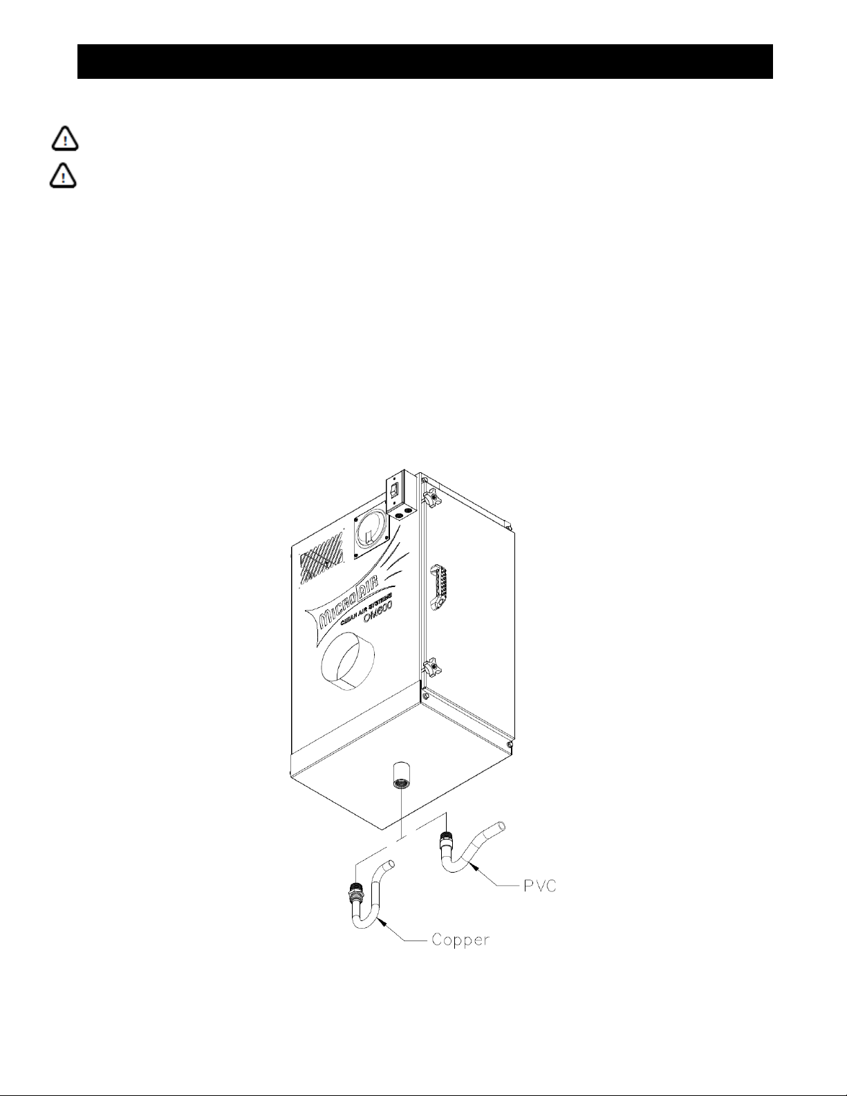
Provision for draining oil from unit is provided by a 1” NPT pipe coupling on the bottom of the unit.
Drainage should be piped to a central collection system. A shut-off valve or drain trap is required to
prevent air bypass through the drain opening. The cabinet may be equipped with either a copper
drain trap or a PVC drain trap (FIG. 4). The drain trap can also be retrofitted.
NOTE: If a shut-off valve is installed in the drain system, the unit must be emptied regularly to
prevent oil from overflowing into the intake duct.
1. For a Copper Trap:
a. The trap must be inserted into the adapter to a depth of 1-1/8”.
b. Use Teflon tape on adapter before installing on cabinet.
2. For a PVC Trap:
a. Use PVC primer and cement to install trap into adapter
b. Use Teflon tape on adapter before installing on cabinet.
FIG. 4

6
OM600 MICRO AIR
PRESSURE GAUGE:
The unit may be equipped with an optional differential pressure gauge, either a Minihelic or a
Magnehelic gauge. The gauge is used to indicate when the filters need to be replaced. Initially, the
gauge will register a small pressure drop across the filters. Record pressure reading. NOTE: The
pressure drop varies with filter combination used. After continued operation, airflow will be reduced
and the gauge will measure increased pressure. Whichever gauge option is selected, it will be
installed from the factory when ordered with the unit. The pressure gauge can also be retrofitted.
CAUTION: Always make sure that the unit is turned off before installing a pressure gauge or
servicing the unit. NEVER run the unit with the access door open or panels removed.
3. Remove parts from package and inspect for any possible damage incurred during shipping.
4. Remove front plate from gauge opening. The top cover may be removed as it will allow for easier
access to plumb gauge, but it is not required.
5. Remove the two 4-Arm knobs from door. Open door to access motor/blower area (FIG. 5).
6. Install gauge onto mounting plate. Note the “HIGH”and “LOW”pressure ports on gauge.
7. Install gauge onto cabinet. NOTE: For units with no gauge, remove the plugs from the pressure
ports in the cabinet.
a. For Magnehelic gauge:
i. Install grommets on pressure port holes inside the cabinet.
ii. Install the (2) male barb fittings on the pressure ports located on the side of the gauge.
Plug the two ports located on the back of the gauge. Fittings come included with the
gauge. NOTE: It is best to install fittings on gauge before mounting.
iii. Plumb the gauge. Run the 1/8” air hose and connect the “LOW” pressure port on the
gauge to the DIRTY air plenum port and “HIGH” pressure port to the CLEAN air plenum
port. Run the air hose through grommets (FIG. 6).
b. For Minihelic gauge:
i. Install grommets on pressure port holes inside the cabinet.
ii. Plumb the gauge. Run the 1/8” air hose and connect the “LOW” pressure port on the
gauge to the DIRTY air plenum port and “HIGH” pressure port to the CLEAN air plenum
port. Run the air hose through grommets (FIG. 6).
8. Close the door and reinstall the top cover (if removed). Reconnect power to the unit. The OM600
is ready to operate.
FIG. 5 FIG. 6

7
OM600 MICRO AIR
CHANGING FILTERS:
CAUTION: Always make sure that the unit is turned off before changing filters or servicing
the unit. NEVER run the unit with the access door open or panels removed.
As the filters collect airborne pollutants, they will eventually become “loaded” with particulate which
will cause airflow to decrease. If the unit equipped with a differential pressure gauge, the gauge will
measure increased pressure (refer to recorded initial pressure reading). NOTE: The Filters might be
wet so allow them to drain first prior to removal.
1. Remove the two 4-Arm knobs from access door. Open door to access filters. NOTE: Door is
hinged and cannot be removed.
2. Remove the Pre-Filters first. Wash them with a detergent solution to remove dirt and oil residue.
Rinse thoroughly with water and let dry.
3. Reinstall pre-filters. Close door and turn the unit on. If the pressure gauge continues to read
high, then the main filter will need to be replaced.
4. Open door to access filters.
5. Loosen the two threaded rods. Remove main filter from unit.
6. Visually inspect the filter. If the pockets are filled with dirt and oil, replace with a new filter.
7. Install main filter and tighten threaded rods to secure filter in place. Note Air Flow arrow on filter.
8. Close the door and start the unit. The pressure gauge should now measure low differential
pressure.
FIG. 7

8
OM600 MICRO AIR
OPTIONAL TOP EXHAUST:
CAUTION: Always make sure that the unit is turned off before servicing the unit. NEVER run
the unit with the access door open or panels removed.
The unit may be equipped with a top exhaust or a HEPA after-filter in lieu of the standard side
exhaust. Both of these options will be installed from the factory when ordered with the unit. Both
options can also be retrofitted.
1. Install standard exhaust covers. Gasketing foam will be supplied and must be installed first on
covers. Use new self-tapping screws to install covers.
2. Remove the top cover from unit and install new top exhaust plate. Install gasketing foam on new
top exhaust plate.
3. For the HEPA after-filter:
a. Install filter on top of exhaust plate. Place filter centered on exhaust. Note that the filter will
have gasket on the inlet (bottom) side. Note air flow arrow on filter.
b. Install Gasketing form on bottom side of HEPA housing.
c. Place housing over filter. Use the threaded rods as guides (4 places). Tighten the four 2-
Arm knobs to secure housing in place.
4. Reconnect power to the unit. The OM600 is ready to operate.
FIG. 8

9
OM600 MICRO AIR
ELECTRICAL INSTALLATION:
1 PHASE, 120V WIRING DIAGRAM:
All electrical work must be done by a qualified electrician according to local, state and
national codes.
For units wired for 120V, 1 Phase, the cabinet will come equipped with a power cord. The single
phase motor is thermally protected with a manual reset button.
FIG. 9

10
OM600 MICRO AIR
1 PHASE, 220V WIRING DIAGRAM:
All electrical work must be done by a qualified electrician according to local, state and
national codes.
The single phase motor is thermally protected with a manual reset button.
FIG. 10

11
OM600 MICRO AIR
3 PHASE WIRING DIAGRAM:
All electrical work must be done by a qualified electrician according to local, state and
national codes.
It is recommended that a magnetic starter and overload protector is used.
FIG. 11

12
OM600 MICRO AIR
GENERAL MAINTENANCE:
1. Occasionally check the condition of the door seals for any leaks. Replace if necessary.
2. Check the blower bearings for unusual wear and the blower wheel for debris and dirt. Clean
when necessary.
3. Periodically inspect hardware for loose nuts and bolts on access doors and internal
components. Tighten if necessary.
4. Check the wiring for loose connections or cracked insulation.
5. No lubrication is required for the motor.
6. Excessive dirt or oil should be removed periodically.
7. Ensure that oil is draining easily through drain pipe. Inspect for blockages.
TROUBLESHOOTING:
CAUTION: Before disassembling the unit or doing any inspecting of the parts, make certain
that the power has been cut off and the blower has come to a complete stop. NEVER run the
unit with the access door opened or the panels removed.
TABLE 1 –Troubleshooting Chart
PROBLEM
POSSIBLE CAUSE
REMEDY
Unit fails to start
No incoming power
Check the circuit and switch
Blown breaker or fuse
Replace fuse or throw breaker
Loose wire in terminal box
Reconnect wire
Burned out motor
Replace motor
Motor thermal trip (1 Phase only)
Reset at motor
Tripped overload (3 Phase only)
Reset overload protector
Unit runs slowly
Wired for wrong voltage
Check input voltage
Inadequate capture
Check wiring diagram
Improper rotation
Check wiring diagram
Switch L1 & L2 (3 Phase only)
Dirty filters
Service filters (see changing filters section)
Vibration
Loose mounting bolts
Tighten bolts
Foreign objects in blower/
Remove debris from blower
Build-up on blower wheel
Dirty filters
Service filters (see changing filters section)

13
OM600 MICRO AIR
PARTS LIST:
FIG. 12

14
OM600 MICRO AIR
ITEM
PART NO.
DESCRIPTION
ITEM
PART NO.
DESCRIPTION
1
34471-01
Cabinet Weldment
14
P3021
Motor, 3/4HP, 3-PH, 230/460V
2
34478-01
Standard Leg (10”)
P7122
Motor, 3/4HP, 1-PH, 115/230V
34478-01
Long Leg (16”)
15
34460-02
Spacer Plate
3
34479-01
Magnehelic Mount Plate
16
P3028
Blower
P2250
Magnehelic Gauge 0-5”
4
34479-02
Minihelic Mount Plate
1-Phase, 120V
P2221
Minihelic Gauge 0-5”
17
30386-02
Cover Plate
5
34479-03
Blank Plate
P1363
Power Cord
6
34459-01
Top Cover
P3025
Electrical Box
7
34480-01
Side Exhaust Cover
P3029
On/Off Switch
34480-02
Front/Back Exhaust Cover
1-Phase, 220V
8
34482-02
Top Exhaust Plate
18
30386-02
Cover Plate
9
34481-01
Top Exhaust Plate HEPA
P3025
Electrical Box
34483-01
HEPA Housing
P7211
On/Off Switch
P3506
2-Arm knob
3-Phase
10
P3649
4-Arm Knob
19
P1234
Cover Plate
11
P7108
Handle
P3025
Electrical Box
12
34486-01
Copper P-Trap
P7216
Copper P-Trap Adapter
13
P7217
PVC P-Trap
P7218
PVC P-Trap Adapter
Filter Options
20
P3032
95% Pleated Main Filter
21
P3033
3” Mist-X Pre-Filter
P3034
1” Mesh Pre-Filter
P3035
2” Mesh Pre-Filter
P3036
2” Baffle Pre-Filter
P3038
2" MaxiGrid Pre-Filter
22
P7201
99.97% HEPA After Filter

15
OM600 MICRO AIR
Notes:
Serial Number:
Supply Voltage:
Date Installed:
Installed By:
L3087
06/22
Table of contents
Popular Industrial Equipment manuals by other brands

Viessmann
Viessmann 4509 Operation manual

Outdoor Water Solutions
Outdoor Water Solutions Large Wood Windmill Assembly instructions

SignWarehouse
SignWarehouse ENDURAPRESS CS15 user manual

DTM System
DTM System MEMO user manual

PCB Piezotronics
PCB Piezotronics IMI SENSORS Spindler Industrial ICP 607A61 Installation and operating manual

INOXPA
INOXPA MCR Ex Installation, service and maintenance instructions