Micro Autonomations Fan Controller v3 User manual
Micro Autonomations LLC –Fan Controller v3
1
Document Rev 1.0
Fan Controller v3
Micro Autonomations LLC
www.ma-embedded.com
© 2014
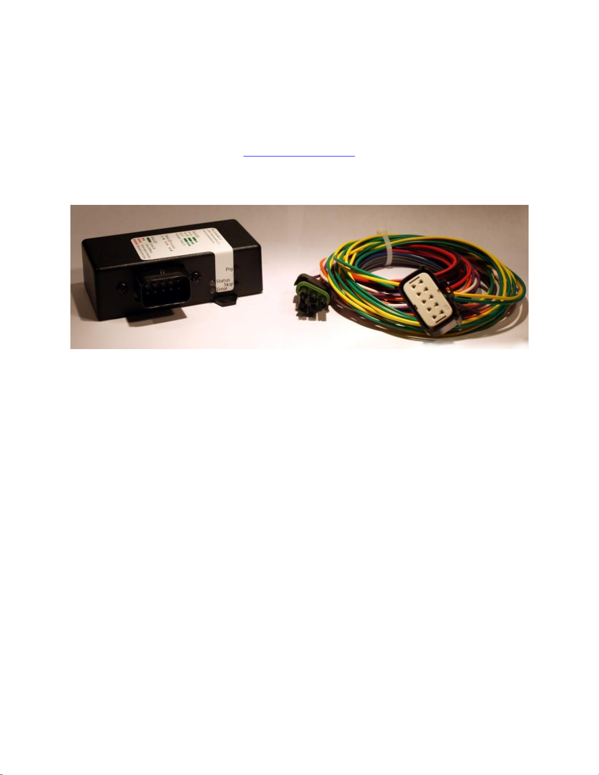
Description
This controller was designed to control C-Class fans from Mercedes. It will work with any standalone
temperature sensor, or it may piggyback on any 5v EFI temperature sensor. Use, described in more
detail later, entails entering programming mode to set the turn on and 75% fan speed temperatures.
The controller will command the fan speed linearly between and above those two temperature set
points.
As a safety feature, if the controller does not detect a temperature sensor, it will turn the fan on; or, if
the active sensor wire gets grounded, it will turn the fan on.

Micro Autonomations LLC –Fan Controller v3
2
Document Rev 1.0
Contents
List of Figures ............................................................................................................................................ 2
Revision History ............................................................................................................................................ 2
Theory of Operation...................................................................................................................................... 3
Maximum Voltage Specifications.................................................................................................................. 4
Pin Diagram................................................................................................................................................... 4
Signal Descriptions........................................................................................................................................ 5
Onboard status LEDs..................................................................................................................................... 7
Wiring Diagrams –One Terminal Sensor ...................................................................................................... 8
Wiring Diagrams –Two Terminal Sensor.................................................................................................. 9
Wiring Diagrams –EFI Sensor ................................................................................................................. 10
Wiring the Fan.............................................................................................................................................11
Recommended sensors............................................................................................................................... 11
Compatibility...............................................................................................................................................12
Programming the controller ....................................................................................................................... 13
Error Modes ................................................................................................................................................16
Troubleshooting..........................................................................................................................................17
Mounting the controller ............................................................................................................................. 18
Warranty .....................................................................................................................................................19
List of Figures
Figure 1 –Fan speed vs. Engine Temperature.............................................................................................. 3
Figure 2 - Pin Diagram................................................................................................................................... 4
Figure 3 - Installing the Remote Status LED to operate either Red or Green............................................... 7
Figure 4 - Wiring with a one terminal temperature sensor installed ........................................................... 8
Figure 5 - Wiring with a two terminal temperature sensor installed ........................................................... 9
Figure 6 - Wiring using a 0-5v EFI temperature sensor............................................................................... 10
Figure 7 - Fan plug wiring............................................................................................................................ 11
Figure 8 - Programming Flowchart ............................................................................................................. 13
Figure 9 - Controller mounting dimensions ................................................................................................18
Revision History
Document version
Changes
Date
Rev 1.0
Initial Release
April 7, 2014
Micro Autonomations LLC –Fan Controller v3
3
Document Rev 1.0
Theory of Operation
The v3 controller has been designed to work in a variety of different systems. It can work with any
standalone temperature sensor, or it may piggyback off any 0-5v EFI temperature sensor. The controller
is able to detect and operate properly with both positive and negative going temperature sensors.
During programming, the controller detects whether the EFI or standalone temperature sensor input is
active. The controller is then able to use this information to aid in detecting various error modes.
During normal operation, the controller reads the current temperature at a rate of once a second. It
then checks several different factors in determining whether to turn the fan on or off, or what speed to
command the fan to operate at. The fan can operate at any speed between 25% and 90%.
After programming, the controller contains two temperature points: the turn on temperature, where
the fan will turn on to 25% speed, and the 75% temperature, where the fan will operate at 75% speed.
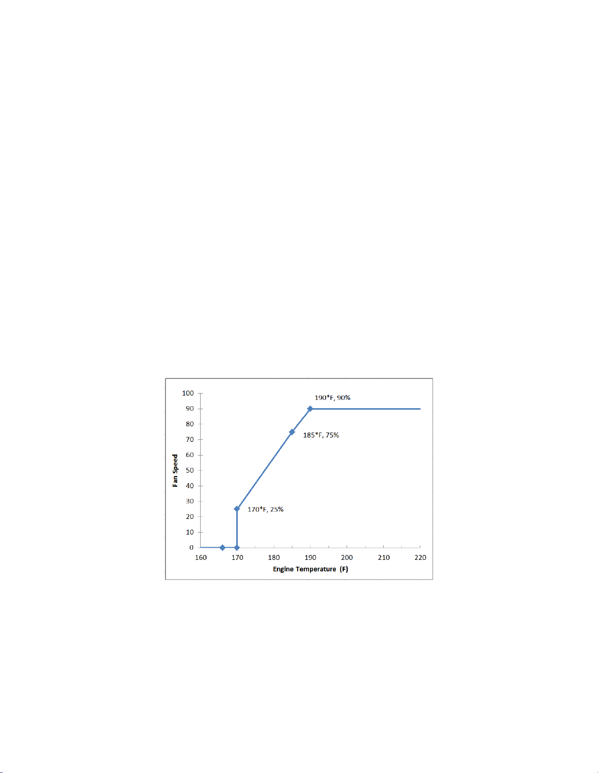
In the figure below, the controller has been programmed with pre-set temperature range #1, with a turn
on temperature of 170°F, and a 75% temperature of 185°F. As the engine temperature rises and
reaches the turn on point, the fan will turn on to 25%. As the engine temperature continues to rise, fan
speed will increase linearly until it reaches 75% speed at 185°. If the engine temperature still continues
to rise, fan speed will continue to increase until it reaches its full speed of 90% at 190°.
Figure 1 –Fan speed vs. Engine Temperature
As the engine temperature decreases, fan speed will also decrease, eventually reaching the 25% turn on
temperature. If the engine temperature continues to decrease below the turn on temperature, it will
maintain 25% fan speed until the engine temperature has dropped approximately 3-5°F below the turn
on temperature. Once the engine temperature is below this hysteresis point, the fan will turn off and
await the need to turn on again.
Micro Autonomations LLC –Fan Controller v3
4
Document Rev 1.0
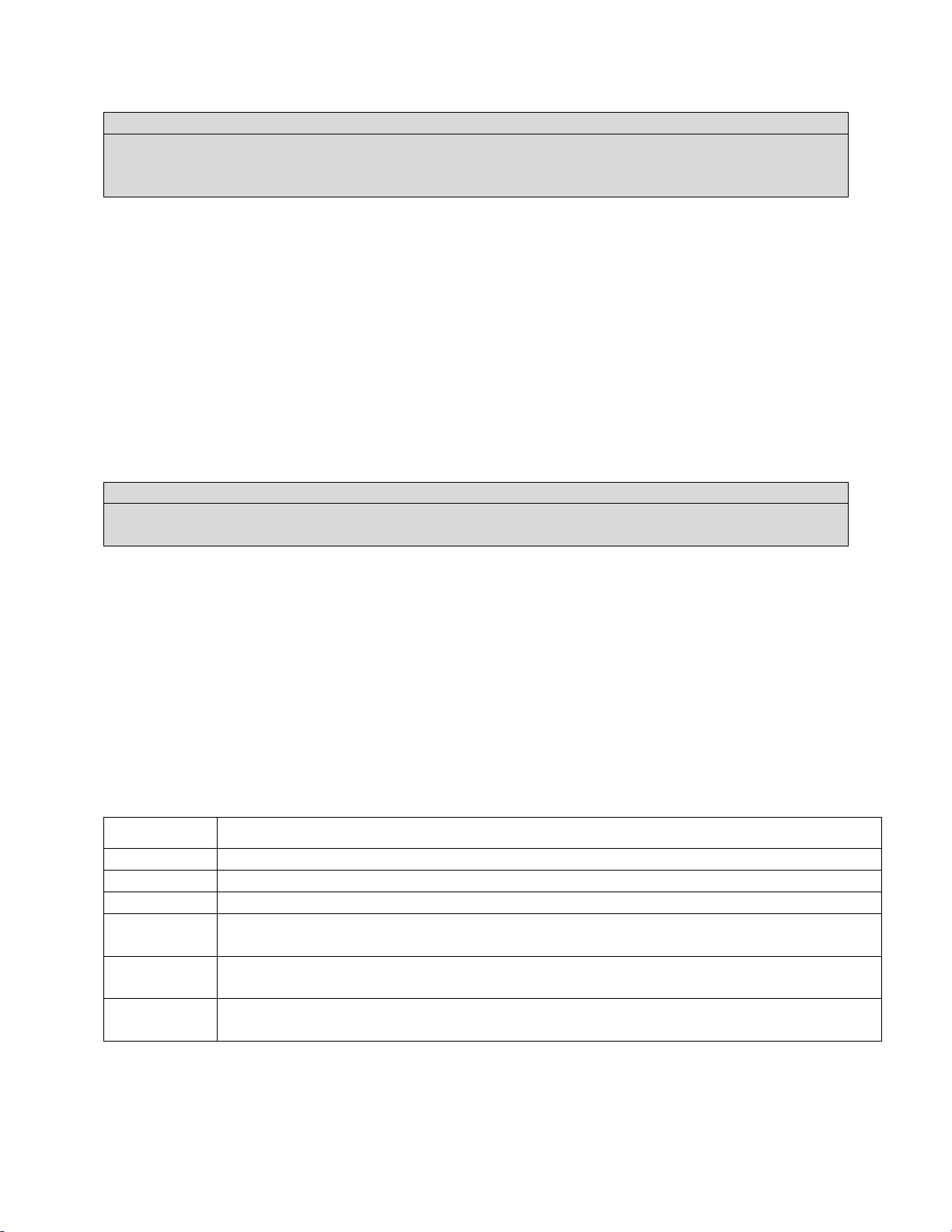
Maximum Voltage Specifications
Maximum input voltage: 18v DC
Maximum voltage on AC input pin: 18v
Maximum voltage on pins 4 and 5: 5v
Do not apply external voltage to any pins other than 1, 3, 4, and 5.
We recommend using 18awg wire to install the controller. Nothing larger is necessary.
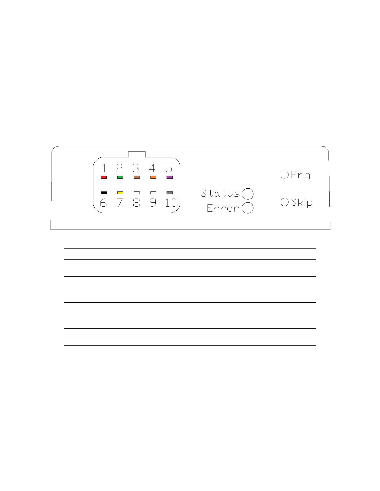
Pin Diagram
Figure 2 - Pin Diagram
Name
Color
Pin Number
Switched 12v Input
Red
1
Trigger Output
Green
2
Air Conditioning Input
Brown
3
Standalone Temperature Sensor (+)
Orange
4
EFI Temperature Sensor
Purple
5
Ground
Black
6
Speed Output
Yellow
7
Not Used
8
Standalone Temperature Sensor Return (GND)
White
9
Remote Status LED
Gray
10

Micro Autonomations LLC –Fan Controller v3
5
Document Rev 1.0
Signal Descriptions
Switched 12v –Red - 1
Main power input to the controller. This must be from a switched source so the controller is off when
the vehicle is off and during cranking. A 5 amp inline fuse is recommended.
Ground –Black - 6
Main ground for the controller. This must have a good connection to ground. This should be wired such
that it is near the main ground point near the battery. The engine ground strap, and the ground for the
fan, should also be located in the same spot.
Note:
Power and Ground to the fan are separate from the controller power and ground, and should include an
inline 50A fuse/breaker minimum
Trigger Output –Green - 2
This is the On/Off signal to the Mercedes Fan. Do not apply any external voltage or ground to this pin.
Do not reverse this wire with the Speed wire. This signal is required for the fan to operate.
Speed Output –Yellow - 7
This is the variable duty cycle speed signal to the Mercedes Fan. Do not apply any external voltage or
ground to this pin. Do not reverse this wire with the Trigger wire. This signal is required for the fan to
operate.
Air Conditioning Input –Brown - 3
This input indicates that the air conditioning (AC) system is operating, and that the fan should be turned
on. This pin may be either grounded, or tied to +12v by the air conditioning system, typically through
the trinary switch. This may also be controlled by a switch to manually turn the fan on. There is a 5
second delay after this signal is active before the fan turns on, and another 5 second delay before it is
turned off. When activated, the fan will operate at 50%. If the engine temperature requires it, fan
speed will automatically increase above 50%.
Note:
This input is optional, and may be left unused.
Standalone Temperature Sensor (+) –Orange - 4
Two Terminal Temperature Sensor –Either terminal may go on this pin. The other terminal
should go to Standalone Temperature Sensor Return (GND).
Single Terminal Temperature Sensor –The one terminal must go to this pin. The body of the
sensor must have a good connection to ground.
Micro Autonomations LLC –Fan Controller v3
6
Document Rev 1.0
Note:
Use this input only if there are no other EFI/gauge connections to the temperature sensor. Connecting
this input to an EFI/gauge signal could change the temperature reported to the EFI system, causing
significant issues.
Standalone Temperature Sensor Return (GND) –White - 9
This pin is internally connected to ground. When using a two terminal temperature sensor, connect one
terminal to this pin. Leave this pin unused when using a single terminal temperature sensor.
EFI Temperature Sensor –Purple - 5
This input may be connected to a temperature sensor connected to an EFI computer system. Its input
range is 0v-5v. Some aftermarket temperature gauges may use a 0-12v signal –verify this before
splicing this wire into the temperature sensor wire. Both positive or negative going sensors may be used
with the controller.
Note:
Use this input if you are piggybacking on the temperature sensor used by MegaSquirt, or any other EFI
system, even if it uses the standard GM sensor
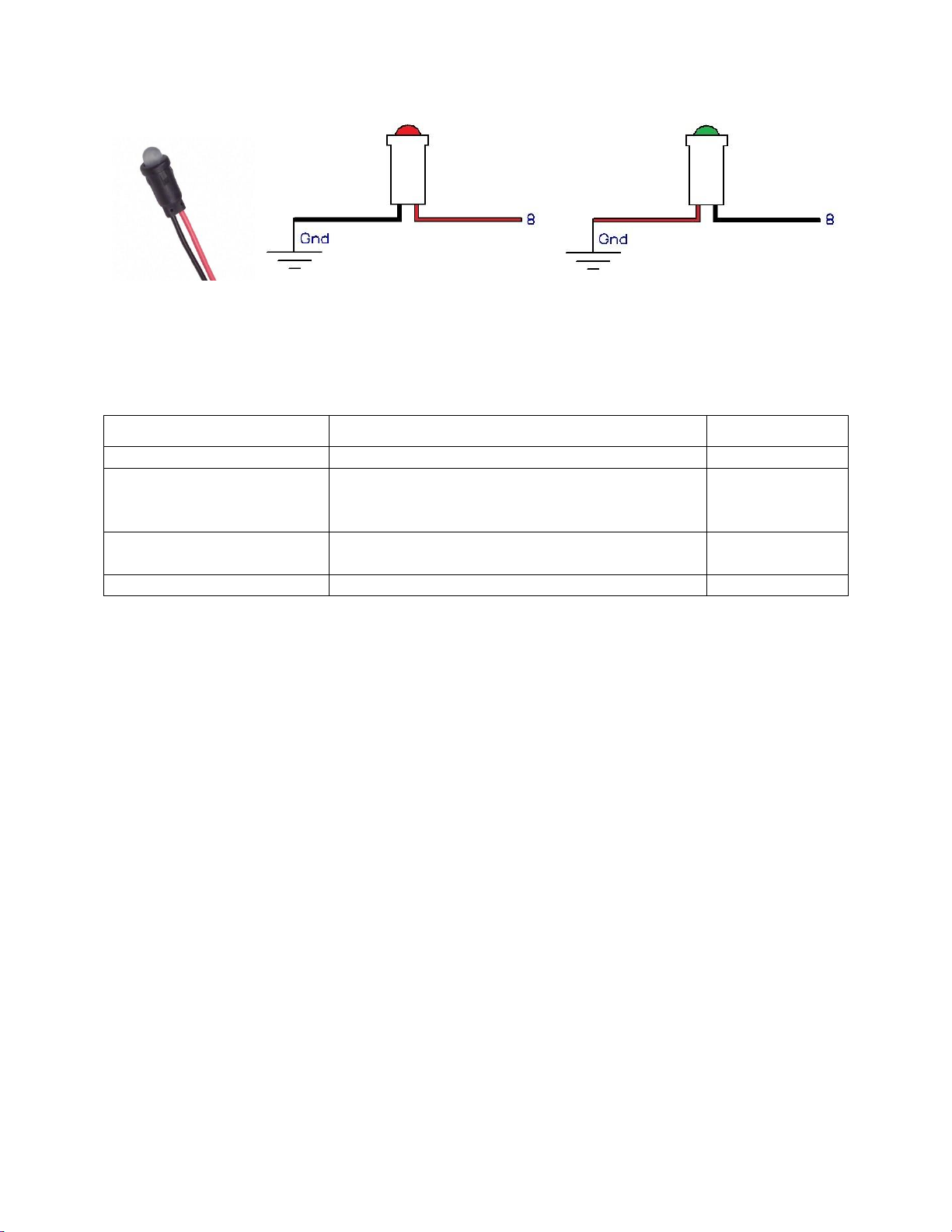
Remote Status LED –Gray - 10
This output may drive the included LED which can be mounted remotely within view of the driver. The
LED is dual color, but only one color may be chosen during installation. Install the Red wire from the LED
to this pin for a Red color, and the other wire to ground. Or, reverse the colors for a Green status light.
The LED requires a ¼” hole to mount in, and has 6” long tinned wires.
The controller is designed to drive an LED with a forward voltage of 2v-2.2v, while supplying 12mA. Any
other suitable LED may be used if desired to match existing indicator lights on the dash. Contact me to
verify that your LED will work if you have any questions.
Mode
Action
Vehicle start
After doing a self-check, if no errors found, the Remote Status LED will be solid for 5 seconds
Fan turns On
When the fan turns on, the Remote Status LED will be solid for 5 seconds, then blink once
Fan turns Off
When the fan turns off, the Remote Status LED will be solid for 5 seconds, then blink twice
Air Cond. is
activated
When the fan is activated by the air conditioning signal, the Remote Status LED will be solid
for 5 seconds, then blink three times
Error
If there is an error, the Remote Status LED will blink in a pattern of 2, 3, or 4 blinks. See the
‘Error Mode’ section for explanation of each code.
Fan at full
speed
If the temperature requires the fan to operate at full speed, the Remote Status LED will turn
on steady until the fan speed drops below full speed
Micro Autonomations LLC –Fan Controller v3
7
Document Rev 1.0
Figure 3 - Installing the Remote Status LED to operate either Red or Green
Onboard status LEDs
There are two LEDs that show the current operating status of the controller.
Mode
Status LED
Error LED
Operating normally, fan off
Off
Green
Fan on
Green->Orange->Red gradient, depending on fan
speed
Green = 25%, Orange = 50%, Red = 90% (full speed)
Green
Error
Red
Blinking error
code
Programming
Various
Various

Micro Autonomations LLC –Fan Controller v3
8
Document Rev 1.0
Wiring Diagrams –One Terminal Sensor
Figure 4 - Wiring with a one terminal temperature sensor installed

Micro Autonomations LLC –Fan Controller v3
9
Document Rev 1.0
Wiring Diagrams –Two Terminal Sensor
Figure 5 - Wiring with a two terminal temperature sensor installed

Micro Autonomations LLC –Fan Controller v3
10
Document Rev 1.0
Wiring Diagrams –EFI Sensor
Figure 6 - Wiring using a 0-5v EFI temperature sensor

Micro Autonomations LLC –Fan Controller v3
11
Document Rev 1.0
Wiring the Fan
The picture below shows the wiring of the fan plug. Power to the fan should be supplied through a 50A
minimum fuse/breaker, connected directly to a main power distribution point.
Figure 7 - Fan plug wiring
Part numbers for the fan plug:
Description
Part Number
Quantity Required
Pin Housing/Bushing
220 545 03 29
1
Large Wire
000 540 36 05
2
Small Wire
000 540 38 05
2
Recommended sensors
Any generic GM type temperature sensor should work with the Controller. We have currently tested
with a TX3T two terminal temperature sensor. The associated pigtail for this sensor is Pico 5615PT. This
sensor has a 3/8” NPT thread.
Autometer #2258. This is a single terminal 1/8” NPT sensor. The sensor body must have a good
connection to ground. You may not be able to use sealant on the threads.

Micro Autonomations LLC –Fan Controller v3
12
Document Rev 1.0
Compatibility
Fan Controller v3 is known to work with the following fans/vehicles
Fan/Vehicle
Notes
2001 to 2007 C-Class Mercedes
600W, 800W
SLK32 AMG Fan
Speed wire to PWM terminal, Trigger to ‘15’.
100k pull-ups on old control lines to avoid CEL
Micro Autonomations LLC –Fan Controller v3
13
Document Rev 1.0
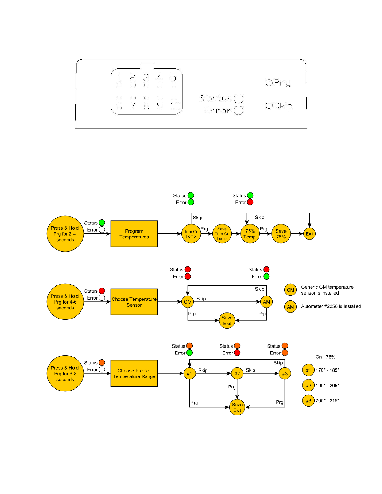
Programming the controller
During programming, the fan will turn off to allow the engine to warm up faster. Press and hold Prg
until the Status LED lights with the color of the sub-menu you wish to enter, then release Prg. Holding
Skip for 4 seconds will exit any programming menu and return the controller to normal operation.
Details about each programming sub-menu can be found on the next page. The Status and Error LEDs
will change colors to indicate the current location in the programming flowchart.
Figure 8 - Programming Flowchart

Micro Autonomations LLC –Fan Controller v3
14
Document Rev 1.0
Program Temperatures:
This mode allows the turn on temperature and 75% speed temperature points to be programmed.
Alternatively, the turn on or the 75% points may be programmed independently of each other, by
skipping one, and saving the other. The full speed temperature is then automatically calculated from
the turn on and 75% temperature points, whenever they are changed.
The controller will automatically detect whether the EFI or standalone temperature sensor is active.
When piggybacking on an EFI sensor, this is the only mode that should be used.
Note:
Choosing a sensor or selecting a pre-set range is disabled when the controller detects that the EFI input
is active
Use:
1. Press and hold Prg for 2 seconds until the Status LED turns green, then release Prg.The fan will
turn off to allow the engine warm up faster
2. When the engine reaches the desired turn on temperature, press Prg to save the new turn on
temperature
2a. Or, press Skip to keep the previously programmed turn on temperature, and continue to
change the 75% temperature
3. Continue idling the engine until it reaches the desired 75% temperature point, then press Prg
again to save the new 75% temperature
3a. Or, press Skip to keep the previously programmed 75% temperature point, and return to
normal operating mode
Programming will then finish, both the Status and Error LEDs will turn off for one second, then the
controller will return to normal operating mode.
Definitions:
Turn on temperature –This is the temperature where the fan will turn on to 25%. The fan will turn off
when the temperature has dropped approximately 3-5*F below the turn on temperature.
75% temperature point –This is the temperature where the fan will operate at 75% speed. When
manually choosing temperature points, after saving a new high point, the fan should immediately turn
on to 75%.
Example:
The engine is idled from cold and allowed to warm up. The turn on temperature is manually set at 180°,
and the 75% temperature is manually set once the engine reaches 200°. This will put the full speed
temperature at 206°, and the fan will turn off after the engine temperature drops below ~176°.
Micro Autonomations LLC –Fan Controller v3
15
Document Rev 1.0
Choose Temperature Sensor:
This option allows selection of the installed temperature sensor to enable the use of one of the pre-set
temperature ranges. If use of a pre-set temperature range is not desired, the controller may be
programmed by setting the turn on and 75% temperature points, and ignoring this option.
Use:
1. Press and hold Prg for 4 seconds, until the Status LED turns Red, then release Prg
2. Press Skip to switch between selecting the GM sensor, and the Autometer (AM) sensor
3. Press Prg to save the currently selected sensor
3a. Or, hold Skip for 4+ seconds to exit programming without changing the previously selected
sensor
By default, when a sensor is chosen, pre-set temperature range #1 will automatically be selected and
saved. The turn on and 75% temperature points may then be selected, or a different temperature range
may be selected.
Note:
Selecting a sensor that is not installed, then selecting a temperature range will result in unexpected fan
behavior
Choose Pre-set Temperature Range:
This mode allows selection of one of three pre-selected temperature ranges, assuming the installed
temperature sensor has already been selected.
The full speed temperature will be automatically calculated from the two temperature points.
Use:
1. Press and hold Prg for 6 seconds, until the Status LED turns Orange, then release Prg
2. Press Skip to switch between the three ranges
3. Press Prg to save the currently selected range
3a. Or, hold Skip for 4+ seconds to exit programming without changing the previously selected
range
Pre-set temperature ranges available for selection:
Range #
Turn On Temperature
75% Temperature
Full Speed Temperature
Error LED color
1
170°
185°
190°
Green
2
190°
205°
210°
Red
3
200°
215°
220°
Orange

Micro Autonomations LLC –Fan Controller v3
16
Document Rev 1.0
Reset all variables:
Press and hold both Prg and Skip together for 10 seconds, until both the Status and Error LEDs turn
Orange, and then release both of them. This will reset the saved temperature points, saved sensor, and
the saved temperature range.
Error Modes
When an error is detected, the Status LED on the controller, and the Remote Status LED (if installed), will
blink a repeating error code. This code consists of the following number of blinks in a row, followed by a
brief pause, then the code again. Only one code will be shown at a time. During each error mode, the
fan will be commanded to run at full speed.
Code
Problem
Solution
2
Current sensor does not match
the stored sensor
-The active temperature sensor (EFI or
standalone) is stored during programming. If
the detected sensor changes to the other
sensor, the fan will operate at full speed until
reprogrammed with the new sensor, or until
the previous sensor is hooked up again.
-The sensors are assumed to be missing if their
voltage is below 0.25v, or above 4.9v.
3
Neither sensor is installed, or
one/both are grounded
-If the active temperature sensor is shorted to
ground, or the wire breaks open, the fan will
operate at full speed.
-Verify that all temperature sensor wires are
connected with no shorts to ground.
-If piggybacking on an EFI sensor, verify that the
correct wire was tapped into. Often, one wire
will be ground, and the other will have the
variable voltage signal.
-For a single terminal sensor, verify a good
connection between the sensor body and
ground. Using tape or sealant on the threads
may prevent it from working properly.
4
Spread between turn on and
75% temperature points are too
close to each other
-The controller requires at least 0.1v between
the turn on and 75% temperature points. Try
re-programming with the turn on point lower,
and/or the 75% point higher.

Micro Autonomations LLC –Fan Controller v3
17
Document Rev 1.0
Troubleshooting
Problem
Solution
Fan does not turn on
-Verify that the fan has a constant 12v to it.
-Verify that the controller has power and that the LEDs are on.
-Verify the Speed and Trigger wiring between the fan and the
controller.
-Test the fan by disconnecting the controller, and jumping 12v to
the Trigger Output signal. After a moment the fan should turn on
and go to full speed.
Fan does not turn on with
air conditioning input
-Verify that the AC system is either grounding or providing 12v to
the air conditioning input.
-Wait 5 seconds for the fan to turn on.
After a short delay, the fan
turns on, and won’t turn off
-Check the Remote Status LED to see if it blinks 3 times after being
steady for 5 seconds. This indicates that the air conditioning
input is active.
-Disconnect the air conditioning input as a temporary test to verify
that the fan no longer turns on after a short delay.
-Verify that the air conditioning input is not being grounded or tied
to +12v, unless the system is commanding it.
Programmed values not
being saved
-Make sure you pressing the Prg button to save values, and not
the Skip button.
Micro Autonomations LLC –Fan Controller v3
18
Document Rev 1.0
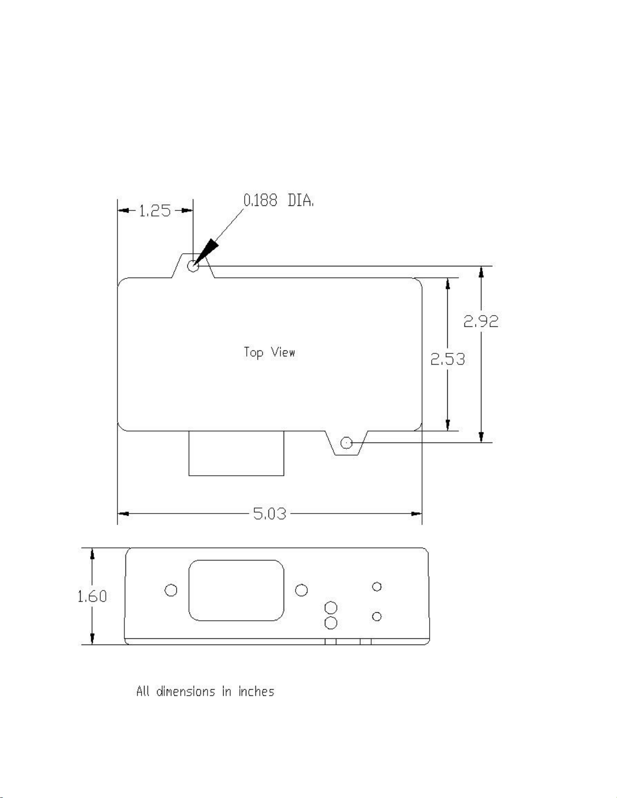
Mounting the controller
We recommend using two #6 self-tapping screws to mount the controller, either in the engine bay, or
under the dash. Mark and predrill the holes, then mount the controller.
The controller is NOT sealed against water, so ensure that any locations will be free from water splashes.
Also, avoid any excessively hot areas under the hood.
Figure 9 - Controller mounting dimensions

Micro Autonomations LLC –Fan Controller v3
19
Document Rev 1.0
Warranty
Micro Autonomations LLC warrants this product to be free from defects in material and workmanship
for a period of twelve (12) months from the date of sale of the original purchaser. Micro Autonomations
LLC will repair this product free of charge if, in the judgment of Micro Autonomations LLC it has been
proven defective within the warranty period. The product should be returned, at the customer expense,
to the location of original purchase. This warranty does not cover any expenses incurred in the removal
and/or reinstallation of the product. Micro Autonomations LLC is limited in liability to the original sale
price of the product.
This warranty does not apply to any product damaged by improper installation, misuse, abuse, improper
line voltage, fire, flood, lightning, or other acts of God, or a product altered or repaired by anyone other
than Micro Autonomations LLC. This warranty is in lieu of other warranties, expressed or implied,
including any implied warranty of merchantability. No person is authorized to assume for Micro
Autonomations LLC any other liability concerning the sale of this product.
Table of contents
Popular Automobile Accessories manuals by other brands

DEFA
DEFA Solid 712800 installation manual

WilTec
WilTec XPOtool 63875 user manual

Rocky Mountain Westy
Rocky Mountain Westy Locking Storage Box installation guide

Saab
Saab 32 025 888 installation instructions

Fiamma
Fiamma 98655A910 Installation and usage instructions

Allen Sports
Allen Sports MT-1 instructions


Husky
Husky RAM 2500 Assembly, Installation, Operation and Maintenance Instructions

Axxess
Axxess AX-ALOC618 installation instructions

Whelen Engineering Company
Whelen Engineering Company G1MM90 installation guide

Conrad
Conrad 85 73 21 operating instructions

Pro-Lift
Pro-Lift Z-Creeper C-2040B Operating instructions & parts manual

Neidhart
Neidhart Performa Racing HMX 8 instruction manual