Pro-Lift Z-Creeper C-2040B Instructions for use

3 IN 1 40” Z-Creeper
This is the safety alert symbol. It is used to alert you to potential personal injury
hazards. Obey all safety messages that follow this symbol to avoid possible
injury or property damage.
Model Number
C-2040B
Operating Instructions & Parts Manual
Printed in China
Capacity
136 kg.
Shinn Fu (Australia) PTY. LTD.
15 Viewtech Place, Rowville, Victoria 3178, Australia

2
Do not use this device for any purpose other than that for which it is expressly intended.
SAFETY AND GENERAL INFORMATION
For your safety, read, understand, and follow the information provided with and on this folding
creeper. The owner and operator shall have an understanding of this product and safe operating
procedures before attempting to use. The owner and operator shall be aware that use of this
product may require special skills and knowledge. Instructions and safety information shall be
conveyed in the operator’s native language before use of this product is authorized. Make certain
that the operator thoroughly understands the inherent dangers associated with the use and misuse
of the product. If any doubt exists as to the safe and proper use of this product, remove from service
immediately.
Inspect before each use. Do not use if there are broken, bent, cracked or damaged parts (including
labels). Any folding creeper that appears damaged in any way, or operates abnormally shall be
removed from service immediately. If the folding creeper has been subjected to a shock load (a load
dropped suddenly, unexpectedly upon it), immediately discontinue use until it has been inspected
by a Pro-Lift authorized service center. It is recommended that an annual inspection be done by
qualified personnel. Labels and Operator’s Manuals are available from manufacturer.
PRODUCT DESCRIPTION
This device is designed to be folded in a “Z” shape for use as a mechanics seat or unfolded for use
as a mechanics creeper. It is intended to be used to support and move, along a smooth and level
surface, rated capacity loads consisting of a single person weighing no more than 136 kg for the
purpose of performing automotive maintenance or service. This device is not intended, designed or
engineered to be used for any other purpose.
Rated Capacity: One person (includes any tools, and equipment) weighing 136 kg. or less.
SPECIFICATIONS
Model Rated Capacity Seat Size Creeper Size
C-2040B 136 kg 365mm x 250mm 40”
CAUTION
Folding components can present pinch and crush hazards during use of this product. Exercise
caution when performing adjustments and always be alert and sober while assembling and using
this equipment.

3
PREPARATION
Before assembling your Folding Creeper, make sure all parts are present. If any part is missing
or damaged, do not attempt to assemble or use the product. Contact Pro-Lift customer service
for replacement parts.
Package Contents: 1 Head Frame Section, 1 Middle Frame Section, 1 Rear Frame Section, 4
Hex Bolts, 8 Washers, 4 Hex Nuts, 6 Casters, 4 Caster Fasteners.
ASSEMBLY INSTRUCTIONS
1. Place Creeper Sections face down, arranged as shown in Fig. 2 (note Middle Section
orientation).
2. Connect Creeper Sections using Hex Bolts, Washers and Nuts. Use two M8 x 60 bolts to
connect Head Frame to Middle Frame. Use two M8 x 55 bolts to Frame to Rear Frame.
Tighten Nuts firmly, but not enough to bind Creeper adjustment.
WARNING
• Read, understand, and follow all instructions before using this device.
• Do not exceed rated capacity. Rated capacity is 136 kg. (includes user, tools, equipment
and personal items).
• Sit down gently. Avoid shock loads caused by jumping or falling onto seat.
• Do not stand on seat.
• Beware of pinch and crush hazards when folding and unfolding.
• Keep out of the reach of children! This device is not appropriate for children’s use.
• Use on smooth, level surfaces only.
Figure 1 - Model C-2040B Components
Rear Frame
Middle Frame
Head Cushion
Head Frame
Figure 2 - Creeper Frame assembly Figure 3 - Attaching Creeper Casters
M8 x 60 Bolt
M8 x 55 Bolt
4
MAINTENANCE
Wipe clean as needed. Use mild upholstery cleaner (not caustic) to clean seat as needed.
Do not lubricate casters!
Figure 6 - Creeper configuration
3. Insert Lock Pin into hole in frame side. Check for proper operation.
4. Using the included open-end wrench, attach two Casters to the threaded holes in the Head
Frame section. Use a 5mm hex key to fasten the remaining four Casters to the Creeper
Frame. Insert the threaded Fasteners from the top and the Casters from the bottom, then
tighten with hex key.
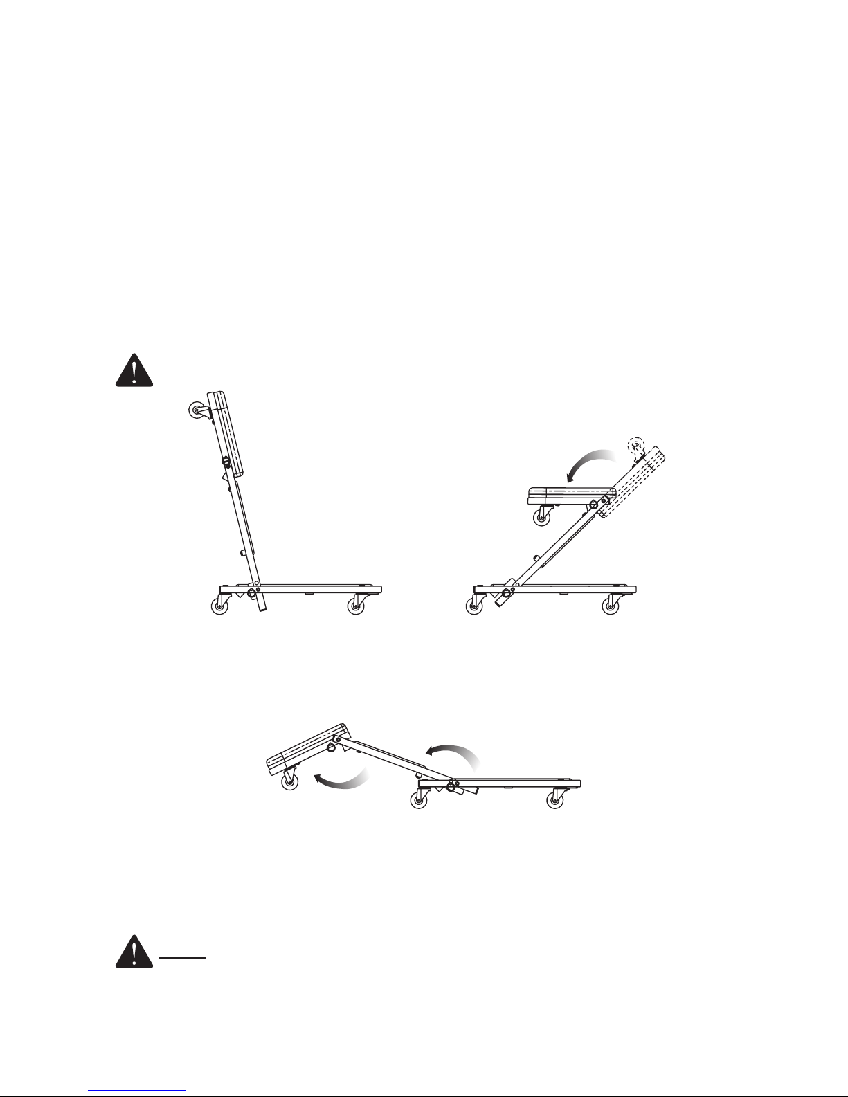
OPERATING INSTRUCTIONS
1. Locate and unlock spring loaded Locking Pin for middle section by pulling out until disengaged.
Then rotate Head Frame and Middle Frame upward as shown in Fig. 4 until the Locking Pin
can engage hole in Creeper Seat locking plate (ensure Lock Pin is fully engaged). This is the
low seat configuration.
2. Disengage Lock Pin for Middle Frame and rotate further forward. Engage locking pin.
Disengage Lock Pin for Head Frame section and rotate backwards as shown in Fig. 5. Adjust
hinged caster brackets as required. This is the high seat configuration.
CAUTION: Ensure all Lock Pins are properly engaged before using creeper.
3. Adjust hinged caster brackets so wheels will contact ground properly. Unlock spring loaded
Lock Pins, then reverse steps 1 and 2, as shown in Fig. 6, to convert Creeper Seat into
Creeper.
Figure 4 - Low seat configuration Figure 5 - High-seat configuration
Table of contents
Popular Automobile Accessories manuals by other brands


ULTIMATE SPEED
ULTIMATE SPEED 279746 Assembly and Safety Advice

SSV Works
SSV Works DF-F65 manual

ULTIMATE SPEED
ULTIMATE SPEED CARBON Assembly and Safety Advice

Witter
Witter F174 Fitting instructions

WeatherTech
WeatherTech No-Drill installation instructions

TAUBENREUTHER
TAUBENREUTHER 1-336050 Installation instruction