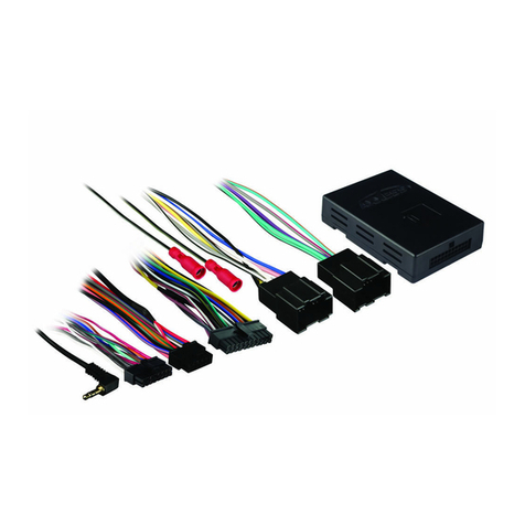
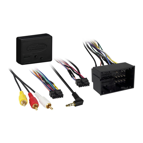
AX-ALOC618
AX-ALOC618
AX-ALOC618
AX-ALOC618
AX-ALOC618
AX-ALOC618
INSTALLATION INSTRUCTIONS INSTALLATION INSTRUCTIONS INSTALLATION INSTRUCTIONS
INSTALLATION INSTRUCTIONSINSTALLATION INSTRUCTIONSINSTALLATION INSTRUCTIONS
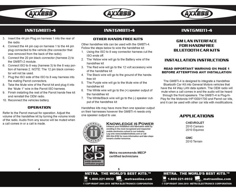
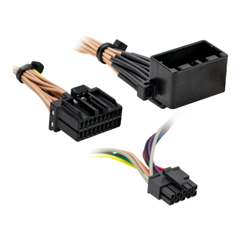
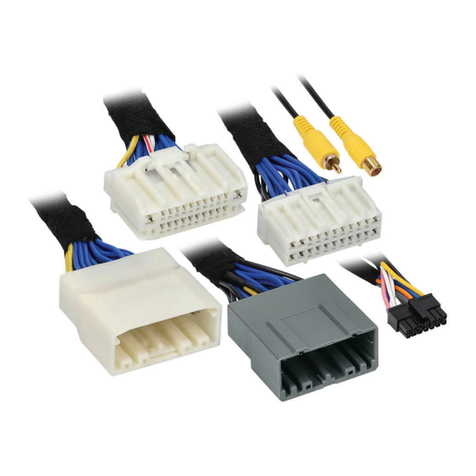
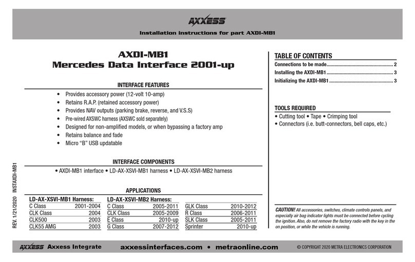
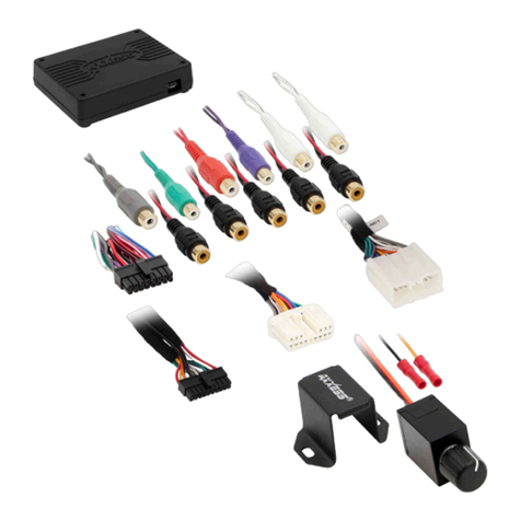
Wire Color & Function: The audio input wire colors are an EIA
standard for car stereo applications as follows.
INPUT HARNESS
WHITE = LEFT Front (+) Input
WHITE/BLACK = LEFT Front (-) Input
GRAY = RIGHT Front + Input
GRAY/BLACK = RIGHT Front (-) Input
BROWN = Reference Ground(-)
(REFERENCE GROUNDOPTIONAL IF NOISE IS PRESENT)
NOTE: Be sure that all audio input connections are polarized or
in phase with each other. That is, the positive output wires from
the audio source need to be connected to the corresponding
positive input wires of the AX-ALOC618. The same goes for the
negative audio wires. Failure to do this will result in poor bass
response and low quality audio.
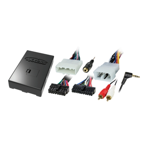
Adjusting the AX-ALOC618 for maximum performance:
After completing all of the necessary connections, turn the AX-
ALOC618 adjustment pots all of the way down by rotating them
completely counter-clockwise. Now, turn the stereo system on
and adjust the main volume control on the stereo to approxi-
mately¾ maximum volume. Select one of the adjustment pots
on the AX-ALOC618 and turn it slowly clockwise until you notice
audio distortion and then stop. Turn the remaining pot to the
same position as the previously adjusted pot. The audio set-up
of the AX-ALOC618 is now complete and ready to be enjoyed.
Wire Color & Function: The audio input wire colors are an EIA
standard for car stereo applications as follows.
INPUT HARNESS
WHITE = LEFT Front (+) Input
WHITE/BLACK = LEFT Front (-) Input
GRAY = RIGHT Front + Input
GRAY/BLACK = RIGHT Front (-) Input
BBROWN = Reference Ground(-)
(REFERENCE GROUNDOPTIONAL IF NOISE IS PRESENT)
NOTE: Be sure that all audio input connections are polarized or
in phase with each other. That is, the positive output wires from
the audio source need to be connected to the corresponding
positive input wires of the AX-ALOC618. The same goes for the
negative audio wires. Failure to do this will result in poor bass
response and low quality audio.
Adjusting the AX-ALOC618 for maximum performance:
After completing all of the necessary connections, turn the AX-
ALOC618 adjustment pots all of the way down by rotating them
completely counter-clockwise. Now, turn the stereo system on
and adjust the main volume control on the stereo to approxi-
mately¾ maximum volume. Select one of the adjustment pots
on the AX-ALOC618 and turn it slowly clockwise until you notice
audio distortion and then stop. Turn the remaining pot to the
same position as the previously adjusted pot. The audio set-up
of the AX-ALOC618 is now complete and ready to be enjoyed.
Wire Color & Function: The audio input wire colors are an EIA
standard for car stereo applications as follows.
INPUT HARNESS
WHITE = LEFT Front (+) Input
WHITE/BLACK = LEFT Front (-) Input
GRAY = RIGHT Front + Input
GRAY/BLACK = RIGHT Front (-) Input
BROWN = Reference Ground(-)
(REFERENCE GROUNDOPTIONAL IF NOISE IS PRESENT)
NOTE: Be sure that all audio input connections are polarized or
in phase with each other. That is, the positive output wires from
the audio source need to be connected to the corresponding
positive input wires of the AX-ALOC618. The same goes for the
negative audio wires. Failure to do this will result in poor bass
response and low quality audio.
Adjusting the AX-ALOC618 for maximum performance:
After completing all of the necessary connections, turn the AX-
ALOC618 adjustment pots all of the way down by rotating them
completely counter-clockwise. Now, turn the stereo system on
and adjust the main volume control on the stereo to approxi-
mately¾ maximum volume. Select one of the adjustment pots
on the AX-ALOC618 and turn it slowly clockwise until you notice
audio distortion and then stop. Turn the remaining pot to the
same position as the previously adjusted pot. The audio set-up
of the AX-ALOC618 is now complete and ready to be enjoyed.
Wire Color & Function: The audio input wire colors are an EIA
standard for car stereo applications as follows.
INPUT HARNESS
WHITE = LEFT Front (+) Input
WHITE/BLACK = LEFT Front (-) Input
GRAY = RIGHT Front + Input
GRAY/BLACK = RIGHT Front (-) Input
BROWN = Reference Ground(-)
(REFERENCE GROUNDOPTIONAL IF NOISE IS PRESENT)
NOTE: Be sure that all audio input connections are polarized or
in phase with each other. That is, the positive output wires from
the audio source need to be connected to the corresponding
positive input wires of the AX-ALOC618. The same goes for the
negative audio wires. Failure to do this will result in poor bass
response and low quality audio.
Adjusting the AX-ALOC618 for maximum performance:
After completing all of the necessary connections, turn the AX-
ALOC618 adjustment pots all of the way down by rotating them
completely counter-clockwise. Now, turn the stereo system on
and adjust the main volume control on the stereo to approxi-
mately¾ maximum volume. Select one of the adjustment pots
on the AX-ALOC618 and turn it slowly clockwise until you notice
audio distortion and then stop. Turn the remaining pot to the
same position as the previously adjusted pot. The audio set-up
of the AX-ALOC618 is now complete and ready to be enjoyed.
INSTAX-ALOC618.pdf 1 11-12-29 下午2:12
