Daikin DFG Series User manual

INSTALLATION INSTRUCTIONS
IOD-1059
12/2022
This forced air central unit design complies with
requirements embodied in The American National Standard
/ National Standard of Canada
ONLY PERSONNEL THAT HAVE BEEN TRAINED TO INSTALL, ADJUST,
SERVICE, MAINTENANCE OR REPAIR
MANUAL SHOULD
PROPERTY
MANUAL, ONLY LICENSED PERSONNEL SHOULD SERVICE THE
PERSONAL
Our connuing commitment to quality products may mean a change in specicaons without noce.
©2022
ナ ン バ ー :
会社名 :
作成日 :
B150
DAIKIN COMFORT TECHNOLOGIES MANUFACTURING, L.P.
2022/2/25
19001 Kermier Rd., Waller, TX 77484

2
When reporting shortages or damages, or ordering repair
parts, give the complete unit model and serial numbers as
stamped on the unit’s nameplate.
Replacement parts for this appliance are available through
your contractor or local distributor. Your nearest distributor
can be located online at www.daikinac.com or by contacting:
These installation instructions cover the outdoor
installation of single package heating and cooling units.
See the Specication Sheet applicable to your model for
information regarding accessories.
Before installing this unit, please read this manual to
familiarize yourself on the specic items which must be
adhered to, including maximum external static pressure to
unit, air temperature rise, minimum or maximum CFM and
motor speed connections.
Keep this literature in a safe place for future reference.

3
CAUTION

4

5
.
Rated performance
is achieved after 20 hours of operation. Rated performance
is delivered at the specied airow. See outdoor unit
specication sheet for split system models or product
specication sheet for packaged and light commercial
models. Specication sheets can be found at www.
daikinac.com for Daikin brand products. Within the website,
please select the residential or commercial products menu
and then select the submenu for the type of product to be
installed, such as air conditioners or heat pumps, to access
a list of product pages that each contain links to that
model’s specication sheet.
To assure that your unit operates safely and eciently, it
must be installed, operated, and maintained in accordance
with these installation and operating instructions, and all
local building codes and ordinances, or in their absence,
with the latest edition of the National Fuel Gas Code
NFPA54/ANSI Z223.1 and National Standard of Canada
CAN/CSA B149 Installation Codes.
This product is designed and manufactured to permit
installation in accordance with National Codes. It is the
installer’s responsibility to install the product in accordance
with National Codes and/or prevailing local codes and
regulations.
The heating and cooling capacities of the unit should be
greater than or equal to the design heating and cooling
loads of the area to be conditioned. The loads should be
calculated by an approved method or in accordance with
ASHRAE Guide or Manual J - Load Calculations published
by the Air Conditioning Contractors of America.

6
Obtain from:
American National Standards Institute
www.ansi.org
System design and installation should also, where
applicable, follow information presented in accepted
industry guides such as the ASHRAE Handbooks. The
manufacturer assumes no responsibility for equipment
installed in violation of any code or regulation. The
mechanical installation of the packaged roof top units
consists of making nal connections between the unit and
building services; supply and return duct connections; and
drain connections (if required). The internal systems of
the unit are completely factory-installed and tested prior to
shipment.
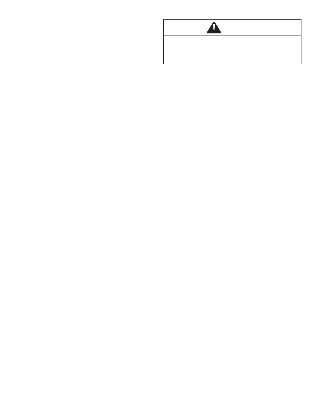
Units are generally installed on a steel roof mounting
curb assembly which has been shipped to the job site for
installation on the roof structure prior to the arrival of the
unit. The model number shown on the unit’s identication
plate identies the various components of the unit such as
refrigeration tonnage, heating input and voltage.
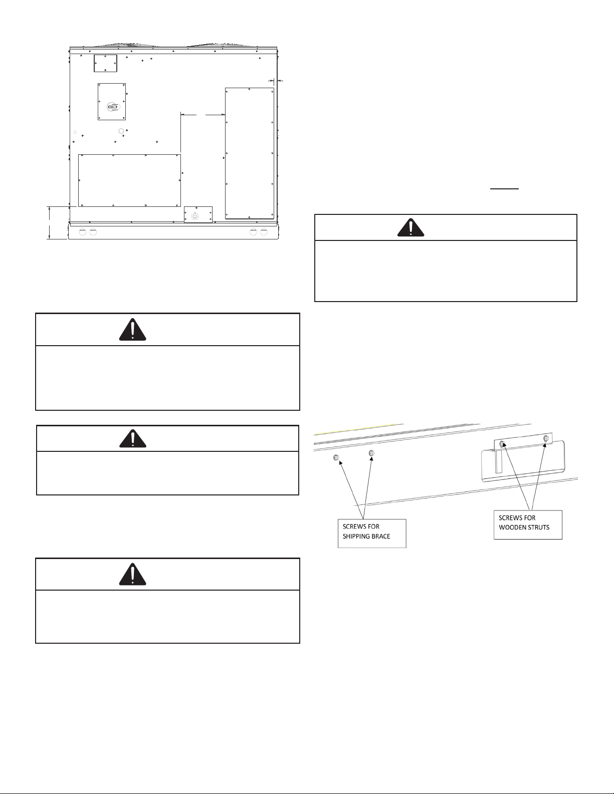
Carefully inspect the unit for damage including damage
to the cabinetry. Any bolts or screws which may have
loosened in transit must be re-tightened.
In the event of damage, the receiver should:
1. Make notation on delivery receipt of any visible
damage to shipment or container.
2. Notify carrier promptly and request an inspection.
3. In case of concealed damage, carrier should be
notied as soon as possible-preferably within 5 days.
4. File the claim with the following supporting
documents:
a. Original Bill of Lading, certied copy, or
indemnity bond.
b. Original paid freight bill or indemnity in lieu
thereof.
c. Original invoice or certied copy thereof,
showing trade and other discounts or
reductions.
d. Copy of the inspection report issued by carrier
representative at the time damage is reported to
the carrier. The carrier is responsible for making
prompt inspection of damage and for a thorough
investigation of each claim. The distributor
or manufacturer will not accept claims from
dealers for transportation damage.
Carefully read all instructions for the installation prior
to installing unit. Ensure each step or procedure is
understood and any special considerations are taken into
account before starting installation. Assemble all tools,
hardware and supplies needed to complete the installation.
Some items may need to be purchased locally.
Unit should be energized 24 hours
prior to compressor start up to ensure crankcase
heater has sufficiently warmed the compressors.
Compressor damage may occur if this step is not
followed.
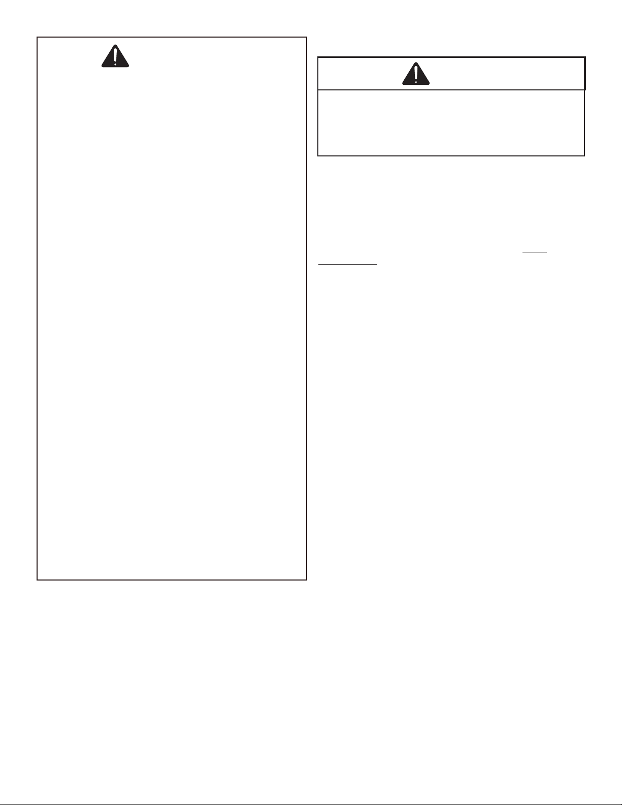
Proper installation of the unit ensures trouble-free
operation. Improper installation can result in problems
ranging from noisy operation to property or equipment
damages, dangerous conditions that could result in injury
or personal property damage and that are not covered by
the warranty. Give this booklet to the user and explain it’s
provisions. The user should retain these instructions for
future reference.
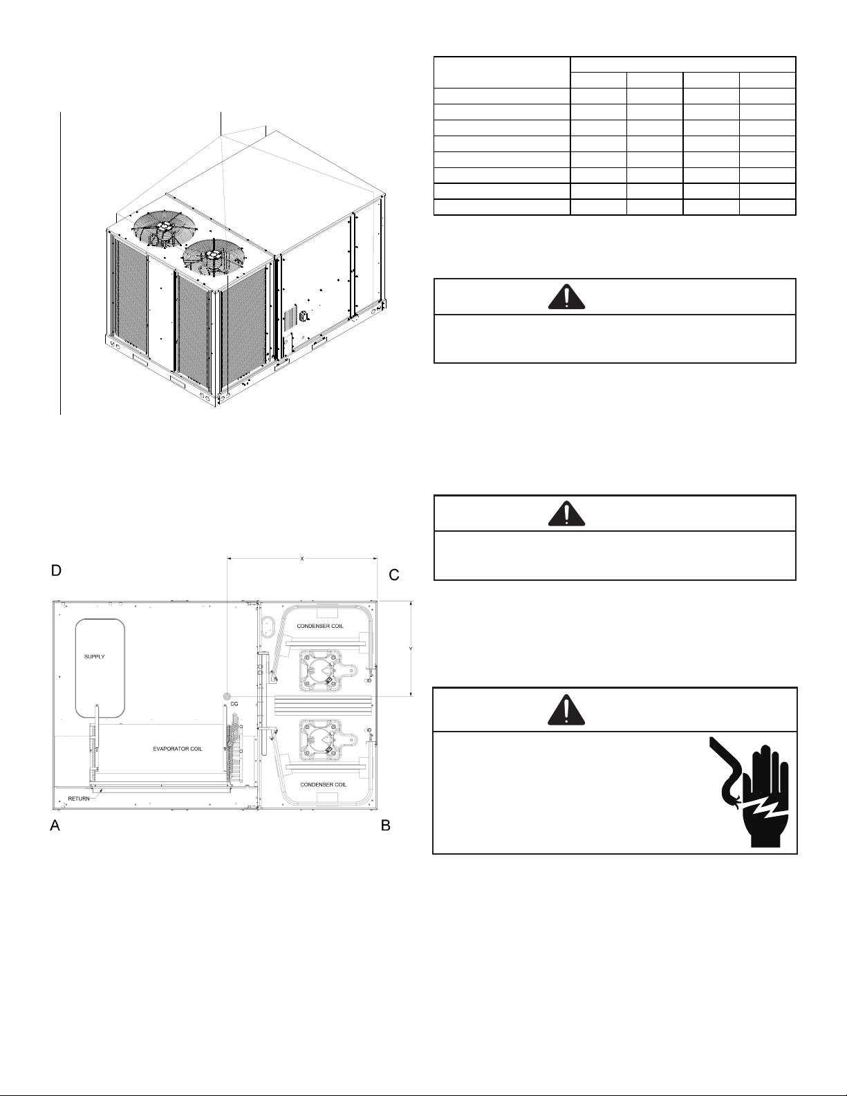
• For proper ame pattern within the heat exchanger
and proper condensate drainage, the unit must be
mounted level.
• The ue outlet must be at least 12 inches from any
opening through which ue gases could enter a
building, and at least three feet above any forced
air inlet located within ten feet. The economizer/
manual fresh air intake/motorized fresh air intake
and combustion air inlet mounted on the unit are not
aected by this restriction.
• To avoid possible corrosion of the heat exchanger,
do not locate the unit in an area where the outdoor
air (i.e. combustion air for the unit) will be frequently
contaminated by compounds containing chlorine
or uorine. Common sources of such compounds
include swimming pool chemicals and chlorine
bleaches, paint stripper, adhesives, paints, varnishes,
sealers, waxes (which are not yet dried) and solvents
used during construction and remodeling. Various
commercial and industrial processes may also be
sources of chlorine/uorine compounds.
• The unit shall not be connected to a chimney ue
serving a separate appliance designed to burn solid
fuel.
• To avoid possible illness or death of the building
occupants, do NOT locate outside air intake device
(economizer, manual fresh air intake, motorized fresh
air intake) too close to an exhaust outlet, gas vent
termination, or plumbing vent outlet. For specic
distances required, consult local codes.

7
• Allow minimum clearances from the enclosure for
re protection, proper operation, and service access
(see unit clearances). These clearances must be
permanently maintained.
• The combustion air inlet and ue outlet on the unit
must never be obstructed. If used, do not allow the
economizer/manual fresh air damper/ motorized fresh
air damper to become blocked by snow or debris. In
some climates or locations, it may be necessary to
elevate the unit to avoid these problems.
• When the unit is heating, the temperature of the return
air entering the unit must be a minimum of 55° F.
• When the unit is installed on the ground adjacent
to the building, a level concrete (or equal) base is
recommended. Prepare a base that is 3" larger than
the package unit footprint and a minimum of 3" thick.
• The base should also be located where no runo of
water from higher ground can collect in the unit.
• To avoid possible property damage or personal injury,
the roof must have sucient structural strength to
carry the weight of the unit(s) and snow or water
loads as required by local codes. Consult a structural
engineer to determine the weight capabilities of the
roof.
• The unit may be installed directly on wood oors or on
Class A, Class B, or Class C roof covering material.
• To avoid possible personal injury, a safe, at surface
for service personnel should be provided.
• As indicated on the unit data plate, a minimum
clearance of 36" to any combustible material is
required on the furnace access side of the unit. All
combustible materials must be kept out of this area.
• This 36" clearance must also be maintained to
insure proper combustion air and ue gas ow. The
combustion air intake and furnace ue discharge must
not be blocked for any reason, including blockage by
snow.
• Adequate clearances from the furnace ue discharge
to any adjacent public walkways, adjacent buildings,
building openings or openable windows must be
maintained in accordance with the latest edition of the
National Fuel Gas Code ANSI Z223.1/NFPA 54.
• Minimum horizontal clearance of 48" from the furnace
ue discharge to any electric meters, gas meters,
regulators and relief equipment is required.
• Do not stand or walk on the unit.
• Do not drill holes anywhere in panels or in the base
frame of the unit except where indicated. Unit access
panels provide structural support.
• Do not remove any access panels until unit has been
installed on roof curb or eld supplied structure.
• Do not roll unit across nished roof without prior
approval of owner or architect.
• Do not skid or slide on any surface as this may
damage unit base. The unit must be stored on a at,
level surface. Protect the condenser coil because it is
easily damaged.
Curb installations must comply with local codes and should
be done in accordance with the established guidelines of
the National Roong Contractors Association.
Proper unit installation requires that the roof curb be rmly
and permanently attached to the roof structure. Check for
adequate fastening method prior to setting the unit on the
curb.
Full perimeter roof curbs are available from the factory
and are shipped unassembled. Field assembly, squaring,
leveling and mounting on the roof structure are the
responsibility of the installing contractor. All required
hardware necessary for the assembly of the sheet metal
curb is included in the curb accessory.
• Sucient structural support must be determined prior
to locating and mounting the curb and package unit.
• Ductwork must be constructed using industry
guidelines. The duct work must be placed into the
roof curb before mounting the package unit. Our full
perimeter curbs include duct connection frames to be
assembled with the curb. Cantilevered type curbs are
not available from the factory.
• Curb insulation, cant strips, ashing and general
roong material are furnished by the contractor.
• The curbs must be supported on parallel sides by roof
members.
• The roof members must not penetrate supply and
return duct opening areas as damage to the unit might
occur.
CAUTION

8
See the manual shipped with the roof curb for assembly
and installation instructions.
*In situations that have multiple units, a 48'' minimum
clearance is required between the condenser coils.
Clearance in accordance with local installation codes, the
requirements of the gas supplier and the manufacturer’s
installation instructions.
Adequate clearance around the unit should be kept for
safety, service, maintenance, and proper unit operation. A
clearance of 48" is recommended on all sides of the unit
to facilitate possible parts replacement, to allow service
access and to insure proper ventilation and condenser
airow. The top of the unit should be completely
unobstructed. If units are to be located under an overhang,
there should be a minimum of 48” clearance and provisions
made to deect the warm discharge air out from the
overhang. The unit should be installed remote from all
building exhausts to inhibit ingestion of exhaust air into the
unit fresh air intake.
7.5, 8.5, & 10 T HEFLUE090120
12.5 T HEFLUE150
After installation, check the top of the curb, duct connection
frame and duct anges to make sure gasket has been
applied properly. Gasket should be rmly applied to the top
of the curb perimeter, duct anges and any exposed duct
connection frame. If gasket is loose, re-apply using strong
weather resistant adhesive.
7.5 to 12.5 Curb 14" Tall 0270L01153
Curb 24" Tall 0270L01154
Inspect curb to ensure that none of the utility services
(electric) routed through the curb protrude above the curb.
CAUTION
Install all duct connections on the unit before placing the
unit on rooftop.
Refer to IOD-7082 included in the literature pack for
installing horizontal duct covers.
Flexible duct connectors between the unit and ducts are
recommended. Insulate and weatherproof all external
ductwork and joints as required and in accordance with
local codes.

9
9-1/2"
13"
1"
SUPPLY
13.9" X 28.3"
RETURN
12.5" X 36.4"
CAUTION
• Unit must be lifted by the four lifting holes located at
the base frame corners.
• Lifting cables should be attached to the unit with
shackles.
• The distance between the crane hook and the top of
the unit must not be less than 60".
• Two spreader bars must span over the unit to prevent
damage to the cabinet by the lift cables. Spreader
bars must be of sucient length so that cables do
not come in contact with the unit during transport.
Remove wood struts mounted beneath unit base
frame before setting unit on roof curb. These struts
are intended to protect unit base frame from fork lift
damage. Removal is accomplished by extracting the
sheet metal retainers and pulling the struts through
the base of the unit. Refer to rigging label on the unit.
• Your unit may be equipped with a steel shipping brace
located underneath the unit (under compressors). If
installing on a roof curb, the brace be removed.
Follow the following instructions for removal.
CAUTION
1. Remove wooden struts per installation instructions.
These are the struts that are located in the fork holes
and are used to protect the unit from damage while
lifting with forks.
2. Locate and remove the four (4) screws that attach the
shipping brace to the side rails. There will be two (2)
screws on each side of the unit. See following gure.
3. Lift unit per the “Rigging Details” section of the
installation instructions, observing all warnings and
cautions. Lift the unit high enough o the ground to
reach under and grasp the shipping brace.
4. Rotate the brace by tapping the ends until the brace
falls free from the unit.
5. Dispose of the brace appropriately.

10
Refer to the Roof Curb Installation Instructions for proper
curb installation. Curbing must be installed in compliance
with the National Roong Contractors Association Manual.
To assist in determining rigging requirements, unit weights
and center of gravity are shown as follows:
090 102 120 150
Corner Weight - A 228 230 304 206
Corner Weight - B 310 318 238 437
Corner Weight - C 236 244 381 241
Corner Weight - D 366 368 296 426
Unit Shipping Weight 1140 1160 1219 1310
Unit Operating Weight 1060 1080 1139 1230
X center 49 49 46 46
Y center 29 29 27 30
DFG Weights (lbs)
Data
CAUTION
Bring condenser end of unit into alignment with the curb
rst. Lower unit carefully onto roof mounting curb. When a
rectangular cantilever curb is used, care should be taken to
center the unit. Check for proper alignment and orientation
of supply and return openings with duct.
CAUTION
Remove spreader bars, lifting cables and other rigging
equipment.

11
CAUTION
CAUTION
For unit protection, use a fuse or HACR circuit breaker that
is in excess of the circuit ampacity, but less than or equal
to the maximum overcurrent protection device. DO NOT
EXCEED THE MAXIMUM OVERCURRENT DEVICE SIZE
SHOWN ON UNIT DATA PLATE.
All line voltage connections must be made through
weatherproof ttings. All exterior power supply and ground
wiring must be in approved weatherproof conduit.
The main power supply wiring to the unit and low voltage
wiring to accessory controls must be done in accordance
with these instructions, the latest edition of the National
Electrical Code (ANSI/NFPA 70), and all local codes and
ordinances.
The main power supply shall be three-phase, three wire.
The unit is factory wired for the voltage shown on the unit’s
data plate.
Main power wiring should be sized for the minimum circuit
ampacity shown on the unit’s database. Size wires in
accordance with the ampacity tables in Article 310 of the
National Electrical Code. If long wires are required, it
may be necessary to increase the wire size to prevent
excessive voltage drop. Wires should be sized for a
maximum of 3% voltage drop.
CAUTION
CAUTION
Ensure the data plate is not covered by the eld-supplied
disconnect switch.
• Some disconnect switches are not fused. Protect the
power leads at the point of distribution in accordance
with the unit data plate.
• The unit must be electrically grounded in accordance
with local codes or, in the absence of local codes,
with the latest edition of the National Electrical Code
ANSI/NFPA 70, and/or the Canadian Electrical Code,
CSA C22.1, Part 1. A ground lug is provided for this
purpose. Do not use the ground lug for connecting a
neutral conductor.
• Connect power wiring to the electrical power block
located within the main control box.

12
LINE VOLTAGE L1, L2, L3
NOTE: CHECK TRANSFORMER TO
MATCH THE CORRECT VOLTAGE TAP
WITH LINE VOLTAGE
Areas Without Convenience Outlet
It is recommended that an independent 115V power source
be brought to the vicinity of the roof top unit for portable
lights and tools used by the service mechanic.
Main power and low voltage wiring may enter the unit
through the condenser end of unit or through the roof curb.
Install conduit connectors at the desired entrance locations.
External connectors must be weatherproof. All holes in the
unit base must be sealed (including those around conduit
nuts) to prevent water leakage into building. All required
conduit and ttings are to be eld supplied.
Supply voltage to roof top unit must not vary by more than
10% of the value indicated on the unit data plate. Phase
voltage unbalance must not exceed 2%. Contact your
local power company for correction of improper voltage or
phase unbalance.
24 23-1/2
SUPPLY
RETURN
LOW VOLTAGE ENTRANCE
HIGH VOLTAGE ENTRANCE
(REMOVE PLUG)
SUPPLY
RETURN
THRU THE CURB

13
"Through the Base Pan Kit" Part Numbers
TTBCKHE02
TTBCKHE02FI (Factory Kit)
1. A 24V thermostat must be installed for unit operation
unless the DDC controls option has been installed.
2. Locate thermostat or remote sensor in the conditioned
space where it will sense average temperature. Do
not locate the device where it may be directly exposed
to supply air, sunlight or other sources of heat. Follow
installation instructions packaged with the thermostat.
3. Use #18 AWG wire for 24V control wiring runs not
exceeding 75 feet. Use #16 AWG wire for 24V control
wiring runs not exceeding 125 feet. Use #14 AWG
wire for 24V control wiring runs not exceeding 200
feet. Low voltage wiring may be National Electrical
Code (NEC) Class 2 where permitted by local codes.
4. Route thermostat wires from sub-base terminals
to the unit. Control wiring should enter through the
condenser panel opening or through curb indicated in
“Electrical Entrance” gure. Connect thermostat and
any accessory wiring to low voltage terminal block
TB1 in the main control box.
The rating plate is stamped with the model number, type of
gas and gas input rating. Make sure the unit is equipped
to operate on the type of gas available. Conversion to
propane (LP) gas is permitted with the use of the factory
authorized conversion kit (see the unit Technical Manual for
the appropriate kit). For High Altitude derates, refer to the
latest edition of the National Fuel Gas Code NFPA 54/ANSI
Z223.1 or National Standard of Canada, Natural Gas and
Propane Installation Code, CSA B149.1.
Installation of this furnace at altitudes above 2000 ft (610
m) shall be made in accordance with the Listed High
Altitude Conversion Kit available with this furnace.”
NATURAL Min. 5.0" W.C., Max. 10.0" W.C.
PROPANE Min. 11.0" W.C., Max. 14.0" W.C.
The minimum supply pressure should not vary from that
shown in the table above because this could prevent the
unit from having dependable ignition. In addition, gas input
to the burners must not exceed the rated input shown
on the rating plate. Overring of the unit could result in
premature heat exchanger failure.

14
The gas line installation must comply with local codes, or
in the absence of local codes, with the latest edition of the
National Fuel Gas Code NFPA 54 / ANSI Z223.1.
1/2 3/4 11 1/4 1 1 /2
10 132 278 520 1050 1600
20 92 190 350 730 1100
30 73 152 285 590 980
40 63 130 245 500 760
50 56 115 215 440 670
60 50 105 195 400 610
70 46 96 180 370 560
80 43 90 170 350 530
90 40 84 160 320 490
100 38 79 150 305 460
Pressure= .50 PSIG or less and Pressure Drop of 0.3" W.C.
(Based on 0.60 Specific Gravity Gas)
Nominal Black Pipe Size (inches)
Length of
Pipe in Feet
Refer to the Proper Piping Practice drawing for the general
layout at the unit. The following rules apply:
1. Use black iron pipe and ttings for the supply piping.
The use of a ex connector and/or copper piping is
permitted as long as it is in agreement with local
codes.
2. Use pipe joint compound on male threads only. Pipe
joint compound must be resistant to the action of the
fuel used.
3. Use ground joint unions.
4. Install a drip leg to trap dirt and moisture before it can
enter the gas valve. The drip leg must be a minimum
of three inches long.
5. Use two pipe wrenches when making connection to
the gas valve to keep it from turning.
6. Install a manual shut-o valve in a convenient location
(within six feet of unit) between the meter and the unit.
7. Tighten all joints securely.
8. The unit must be connected to the building piping by
one of the following methods:
• Rigid metallic pipe and ttings
• Semirigid metallic tubing and metallic ttings
(Aluminum alloy tubing must not be used in
exterior locations).
• Listed gas appliance connectors used in
accordance with the terms of their listing
that are completely in the same room as the
equipment. Always use a new listed connector.
• In the prior two methods above the connector
or tubing must be protected from physical
and thermal damage. Aluminum alloy tubing
and connectors must be coated to protect
against external corrosion when in contact with
masonry, plaster or insulation or are subject to
repeated wettings by liquids (water - not rain
water, detergents or sewage).
CAUTION

15
There will be air in the gas supply line after testing for leaks
on a new installation. Therefore, the air must be bled from
the line by loosening the ground joint union until pure gas
is expelled. Tighten union and wait for ve minutes until all
gas has been dissipated in the air. Be certain there is no
open ame in the vicinity during air bleeding procedure.
The unit is placed in operation by closing the main
electrical disconnect switch for the unit.
All propane gas equipment must conform to the safety
standards of NFPA 58 - Liqueed Petroleum Gas Code.
For satisfactory operation, propane gas pressure must be
within 9.7 - 10.3 inches w.c. for high re at the manifold
with all gas appliances in operation. Maintaining proper
gas pressure depends on three main factors:
1. Vaporization rate, which depends on (a) temperature
of the liquid, and (b) wetted surface area of the
container or containers.
2. Proper pressure regulation.
3. Pressure drop in lines between regulators, and
between second stage regulator and the appliance.
Pipe size required will depend on length of pipe run
and total load of all appliances.
Complete information regarding tank sizing for
vaporization, recommended regulator settings and pipe
sizing is available from most regulator manufacturers and
propane gas suppliers.
Since propane gas will quickly dissolve white lead or most
standard commercial compounds, special pipe dope must
be used. Shellac base compounds resistant to the actions
of liqueed petroleum gases such as Gasolac®, Stalactic®,
Clyde’s®or John Crane®are satisfactory.
See the following gure for typical propane gas piping.
The gas supply piping location and installation for roof
top units must be in accordance with local codes or, in
the absence of locals codes, with ordinances of the latest
edition of the National Fuel Gas Code ANSI Z223.1/NFPA
54.
A manual gas shut o valve must be eld installed external
to the roof top unit. In addition, a drip leg must be installed
near the inlet connection. A ground joint union connection
is required between the external shut o valve and the unit
connection to the gas valve to permit removal of the burner
assembly for servicing.
1. Route gas piping to unit so that it does not interfere
with the removal of access panels. Support and
align piping to prevent strains or misalignment of the
manifold assembly.
2. All units are furnished with standard female 1/2" NPT
pipe connections. The size of the gas supply piping
to the unit must be based on length of run, number
of units on the system, gas characteristics, BTU
requirement and available supply pressure. All piping
must be done in accordance with local codes or, in the
absence of local codes, with the latest edition of the
National Fuel Gas Code
ANSI Z223.1/NFPA 54.

16
3. These units are designed for either natural or
propane (LP) gas and are specically constructed at
the factory for only one of these fuels. The fuels are
NOT interchangeable. However, the furnace can be
converted in the eld from natural gas to LP gas with
the appropriate factory kit (see unit Technical Manual
for the appropriate kit). Only a qualied contractor,
experienced with natural and propane gas systems,
should attempt conversion. Kit instructions must
be followed closely to assure safe and reliable unit
operation.
4. With all units on a common line operating under
full re, natural gas main supply pressure should
be adjusted to approximately 7.0” w.c., measured
at the unit gas valve. If the gas pressure at the
unit is greater than 10.5” w.c., the contractor must
furnish and install an external type positive shut o
service pressure regulator. The unit will not function
satisfactorily if supply gas pressure is less than 5.5”
w.c. or greater than 10.5” w.c..
5. With all units on a common line operating under
full LP gas main supply pressure should be at least
11.0” w.c. and must be no greater than 14.0” w.c.,
measured at the unit gas valve. Unit will not function
satisfactorily if supply gas pressure is less than 11.0”
w.c. or greater than 14.0” w.c..
6. All pipe connections should be sealed with a pipe
thread compound, which is resistant to the fuel used
with the furnace. A soapy water solution should be
used to check all joints for leaks. A 1/8” NPT plugged
tap is located on the entering side of the gas valve for
test gauge connection to measure supply (main) gas
pressure. Another 1/8” tap is provided on the side of
the manifold for checking manifold pressure.
CAUTION
7. There must be no obstruction to prevent the ow of
combustion and ventilating air. A vent stack is not
required and must never be used. The power venter
will supply an adequate amount of combustion air
as long as the air passageways are kept free of any
obstructions and the recommended external unit
clearances are maintained.
The supply duct from the unit through a wall may be
installed without clearance. However, minimum unit
clearances must be maintained (see “Clearances" section).
The supply duct should be provided with an access panel
large enough to inspect the air chamber downstream of
the heat exchanger. A cover should be tightly attached to
prevent air leaks.
Ductwork dimensions are shown in the roof curb
installation manual.
If desired, supply and return duct connections to the unit
may be made with exible connections to reduce possible
unit operating sound transmission.
The inductor motor on DFG units is a dual voltage motor. It
is factory wired for 230 volts. If eld supply power is 208V,
the installer must swap the connections of the black and
red leads (located in the blower compartment) to ensure
correct inductor motor operation.
A 3/4" female NPT drain connection is supplied on the
end of the unit and bottom of the drain pan for condensate
piping. An external trap must be installed for proper
condensate drainage. Hand tighten drain tting to the drain
connection.

17
NOTE: Trap should be deep enough to offset maximum
unit static difference. A minimum 4” trap is recommended.
Drain Plug Roof Curb
See NOTE
Base Rail
Open Vent 2” Min
Install condensate drain trap as shown. Use 3/4" drain line
and ttings or larger. Do not operate without trap.
Drainage of condensate directly onto the roof may be
acceptable; refer to local code. It is recommended that a
small drip pad of either stone, mortar, wood or metal be
provided to prevent any possible damage to the roof.
To use the bottom drain connection, remove the drain plug
from the bottom connection and install it in the horizontal
connection.
Due to the fact that the drain pans in any air conditioning
unit will have some moisture in them, algae and fungus
will grow due to airborne bacteria and spores. Periodic
cleaning is necessary to prevent the build-up from plugging
the drain.
To remove the drain pan for cleaning, remove the drain pan
cover rst (located in horizontal drain pans) then the drain
pan could be slid out.
CAUTION
Prior to the beginning of Startup, Adjustments, and Checks
procedures, the following steps should be completed in the
building.
This unit is equipped with an electronic ignition device to
automatically light the main burners. It also has a power
vent blower to exhaust combustion products.
On new installations, or if a major component has been
replaced, the operation of the unit must be checked.
Check unit operation as outlined in the following
instructions. If any sparking, odors, or unusual sounds
are encountered, shut o electrical power and recheck for
wiring errors, or obstructions in or near the blower motors.
The Startup, Adjustments, and Checks procedure provides
a step-by-step sequence which, if followed, will assure the
proper startup of the equipment in the minimum amount of
time. Air balancing of duct system is not considered part
of this procedure. However, it is an important phase of any
air conditioning system startup and should be performed
upon completion of the Startup, Adjustments, and Checks
procedure. The Startup, Adjustments, and Checks
procedure at outside ambients below 55°F should be
limited to a readiness check of the refrigeration system with
the required nal check and calibration left to be completed
when the outside ambient rises above 55°F.
If the unit is to be used for temporary heating or cooling,
a “Startup, Adjustments, and Checks" must rst be
performed in accordance with this manual. Damage or
repairs due to failure to comply with these requirements
are not covered under the warranty. the machines
are used for temporary heating or cooling, inspect the coils,
fans, and motors for unacceptable levels of construction
dust and dirt and install new lters.

18
The installing contractor must be certain that:
• All supply and return air ductwork is in place, properly
sealed, and corresponds with installation instructions.
• All thermostats are mounted and wired in accordance
with installation instructions.
• All electric power, all gas, hot water or steam line
connections, and the condensate drain installation
have been made to each unit on the job. These
main supply lines must be functional and capable of
operating all units simultaneously.
• Requirements are met for venting and combustion air.
• Air lters are in place.
• Input rate and temperature rise are adjusted per rating
plate.
Inspect the roof curb for correct installation. The unit and
curb assembly should be level. Inspect the ashing of the
roof mounting curb to the roof, especially at the corners, for
good workmanship. Also check for leaks around gaskets.
Note any deciencies in a separate report and forward to
the contractor.
Remove any extraneous construction and shipping
materials that may be found during this procedure. Rotate
all fans manually to check for proper clearances and that
they rotate freely. Check for bolts and screws that may
have jarred loose during shipment to the job site. Re-
tighten if necessary. Re-tighten all electrical connections.
Verify that all duct connections are tight and that there is no
air bypass between supply and return.
Remove lter section access panels and check that lters
are properly installed. Note airow arrows on lter frames.
Ensure the transformer and induced draft motor are set on
the appropriate voltage taps. Both the transformer tap and
induced draft motor are set on 230v from the factory. To
change the induced draft motor voltage, remove the black
induced draft motor wire from the unused terminal on the
ignition control board and swap it with the red wire coming
from the induced draft motor.
It is important to your safety that the unit has been properly
grounded during installation. Check ground lug connection
in main control box for tightness prior to closing circuit
breaker or disconnect switch. Verify that supply voltage
on line side of disconnect agrees with voltage on unit
identication plate and is within the utilization voltage
range as indicated in Appendix B Electrical Data.
That nominal voltage value assigned
to a circuit or system for the purpose of designating its
voltage class.
That voltage assigned to a piece of
equipment for the purpose of designating its voltage class
and for the purpose of dening the minimum and maximum
voltage at which the equipment will operate.
The voltage of the line terminals
of the equipment at which the equipment must give fully
satisfactory performance. Once it is established that supply
voltage will be maintained within the utilization range under
all system conditions, check and calculate if an unbalanced
condition exists between phases. Calculate percent voltage
unbalance as follows.
Three Phase Models Only
Close the disconnect switch to energize control
transformer. Check primary and secondary (24V) of control
transformer.
When the nal adjustments are complete, the current
draw of the motor should be checked and compared to
the full load current rating of the motor. The amperage
must not exceed the service factor stamped on the motor
nameplate. The total airow must not be less than that
required for operation of the furnace.
If an economizer is installed, check the unit operating
balance with the economizer at full outside air and at
minimum outside air.
Adjust the CFM for the unit by changing the position of
the low voltage leads on the terminal block TB1. Refer to
Appendix A for blower performance at each speed tap. The
table below shows RECOMMENDED SPEED TAPS for
heating and cooling. Refer to Appendix D for maximum and
minimum allowed airow for heating and cooling.

19
DFG Model Wiring
GR (FAN)
Energized during Heat Mode
BR (Heating Stage 2)
PU (Cooling Stage 2)
WH (Heating Stage 1)
YL (Cooling Stage 1)
** TB1-DH is energized when the unit is in heat
mode. When TB1-DH is energized, the blower motor
operates at a new group of programmed speeds,
T6-T10, in place of T1-T5.
• Move YELLOW (YL) wire from TB1-T1 to T2 to change blower speed during cooling stage 1 operation.
(Do not move wires YL and PU to the same taps)
• Move WHITE (WH) wire from TB1-T6 to T7 to change blower speed during heating stage 1 operation.
(Do not move wires WH and BR to the same taps)
• Move PURPLE (PU) wire from TB1-T3 to T4 or T5 to change blower speed during cooling stage 2 operation.
(Do not move wires YL and PU to the same taps)
• Move BROWN (BR) wire from TB1-T8 to T9 or T10 to change blower speed during heating stage 2 operation.
(Do not move wires WH and BR to the same taps)
AC GY1 Y2 W1 W2 DH T1 T2 T3 T4 T5 T6 T7 T8 T9 T10
Fan Only XGR
Cooling Mode LO XX
Cooling Mode HI XXX
Heating Mode Lo XX
Heating Mode HI X XX
DFGOPERATION
WIRE RANGE
DFGOPERATION and WIRE RANGE CHART
X= 24V Signal
= Range of AVAILABLE TAPS
For wire color information and placement, view DFG Model Wiring
Electrical Input Check
Make preliminary check of evaporator fan ampere draw and verify that motor nameplate amps are not exceeded.
A nal
check of amp draw should be made upon completion of air balancing of the duct system (see Appendix B).\

20
Actual RPM’s must be set and veried with a tachometer
or strobe light. Refer to Appendex A for basic unit fan
RPM. Refer also to “Airow” section of this manual. With
disconnect switch open, disconnect thermostat wires
from terminals Y and W. This will prevent heating and
mechanical cooling from coming on. Place a jumper wire
across terminals R and G at TB1 terminal block. Close
disconnect switch; evaporator fan motor will operate so
RPM can be checked.
Make preliminary check of evaporator fan ampere draw
and verify that motor nameplate amps are not exceeded. A
nal check of amp draw should be made upon completion
of air balancing of the duct system (see Appendix B).
The rst step in checking out the gas-red furnace is to test
the gas supply piping to the unit for tightness and purge the
system of air using methods outlined in the latest edition of
the National Fuel Gas Code ANSI Z223.1 / NFPA 54. Verify
that the disconnect switch is in the “OFF" position. A soapy
water solution should be used to check for gas leaks.
Since the unit is subject to considerable jarring during
shipment, it is extremely important that all gas connections
and joints be tested for tightness. Gas piping downstream
from the unit inlet should be checked for leaks during the
subsequent sequence check.
The supply gas pressure should be adjusted to 7.0” w.c.
on natural gas and 11.0” on LP gas with the gas burners
operating. If there is more than one unit on a common gas
line, the pressures should be checked with all units under
full re. A supply pressure tap is provided on the upstream
side of the gas valve. A manifold pressure tap is provided
on the manifold. The normal manifold pressure for full input
is 3.5” w.c. on natural gas and 10.0” w.c. for propane gas.
Minimum gas supply pressure is 5.5” w.c. for natural gas
and 11.0” for propane gas. In order to obtain rating, gas
supply pressure must be 11.0” w.c. for propane gas.
The pressure regulator on LP gas models is adjusted for
10.0” w.c. manifold pressure and is intended to prevent
over-ring only. Do not attempt adjustment of the built-in
pressure regulator unless the supply pressure is at least
7.0” w.c. on natural gas or 14.0” w.c. on propane gas.
Check the location of the ignition electrode and the ame
sensor for correct gap setting.
Ton Model
High Fire
Rate
Btu/Hr
No. of
Burners
N.G.
Orfice
Drill #
L.P. Orfice
Drill #
130,000 5 41 54
180,000 6 37 53
225,000 7 36 52
130,000 5 41 54
180,000 6 37 53
225,000 7 36 52
130,000 5 41 54
180,000 6 37 53
240,000 7 36 52
130,000 5 41 54
180,000 6 37 53
240,000 7 36 52
7.5
8.5
10
12.5
DFG102
DFG090
DFG120
DFG150
Other manuals for DFG Series
1
This manual suits for next models
4
Table of contents
Other Daikin Accessories manuals

Daikin
Daikin DPS User manual

Daikin
Daikin AKZ8 Series User manual

Daikin
Daikin KRCS01-7B User manual

Daikin
Daikin homecontrols EKRSENDI1BA User guide

Daikin
Daikin FWTSKA Owner's manual

Daikin
Daikin EKRSCA1 User manual

Daikin
Daikin KRCS01-8B User manual

Daikin
Daikin FWHSK User manual

Daikin
Daikin DWSC - Vintage C User manual

Daikin
Daikin DFC Series User manual