MICRO-EPSILON Industrial Performance Unit User manual

Operating Instructions
Industrial Performance Unit

MICRO-EPSILON
MESSTECHNIK
GmbH & Co. KG
Königbacher Str. 15
94496 Ortenburg / Deutschland
Tel. +49 (0) 8542 / 168-0
Fax +49 (0) 8542 / 168-90
e-mail [email protected]
www.micro-epsilon.com

Industrial Performance Unit
Contents
1. Safety ........................................................................................................................................ 5
1.1 Symbols Used ................................................................................................................................................. 5
1.2 Warnings.......................................................................................................................................................... 5
1.3 Notes on CE Marking ...................................................................................................................................... 6
1.4 Notes on FCC Marking .................................................................................................................................... 6
1.5 Intended Use ................................................................................................................................................... 6
1.6 Proper Environment......................................................................................................................................... 6
2. Functional Principle, Technical Data ....................................................................................... 7
2.1 Short Description............................................................................................................................................. 7
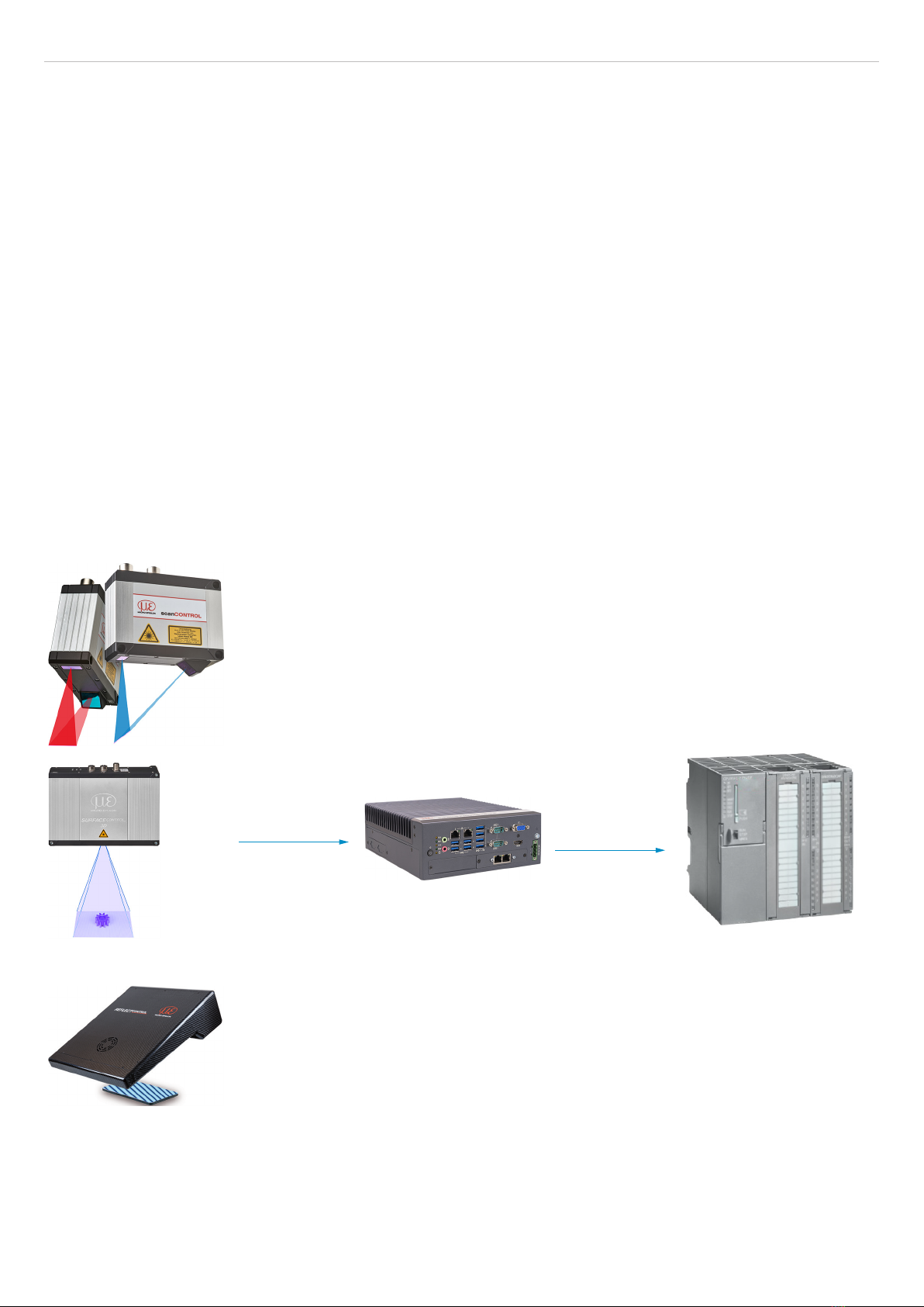
2.2 System Design................................................................................................................................................. 7
2.3 Special Performance Features ........................................................................................................................ 8
2.4 Technical Data ................................................................................................................................................. 8
2.5 Control and Indicator Elements....................................................................................................................... 9
3. Delivery ................................................................................................................................... 10
3.1 Unpacking/Included in Delivery .................................................................................................................... 10
3.2 Storage .......................................................................................................................................................... 10
4. Installation and Assembly...................................................................................................... 11
4.1 Controller ....................................................................................................................................................... 11
4.2 Electrical Connections................................................................................................................................... 12
4.2.1 Connection Diagram .................................................................................................................... 12
4.2.2 Interfaces ...................................................................................................................................... 13
4.2.3 Supply Voltage (Power)................................................................................................................ 13
4.3 Installation instructions .................................................................................................................................. 14
4.4 Initial Operation.............................................................................................................................................. 14
5. Operating System................................................................................................................... 15
6. Operation ................................................................................................................................ 16
6.1 Turning On ..................................................................................................................................................... 16
6.2 System Start-Up............................................................................................................................................. 16
6.3 Users and Passwords.................................................................................................................................... 16
6.4 Setting Up for Initial Use................................................................................................................................ 17
7. Setting Up Fieldbus Operation .............................................................................................. 18
7.1 General .......................................................................................................................................................... 18
7.2 Running Firmware on the Fieldbus Card ...................................................................................................... 18
7.3 Operating Program........................................................................................................................................ 19
8. Limitation of Liability ............................................................................................................. 20
9. Service, Repair ...................................................................................................................... 20
10. Decommissioning, Disposal .................................................................................................. 21
Appendix................................................................................................................................. 22
A 1 Further Literature ................................................................................................................... 22
A 2 Accessories ............................................................................................................................ 22

Industrial Performance Unit

Page 5
Safety
Industrial Performance Unit
1. Safety
System operation assumes knowledge of the operating instructions. The Industrial Performance Unit will also be referred
to in the following as “controller”.
1.1 Symbols Used
The following symbols are used in these operating instructions:
Indicates a hazardous situation which, if not avoided, may result in minor or moderate injury.
Indicates a situation that may result in property damage if not avoided.
Indicates a user action.
iIndicates a tip for users.
Measurement Indicates hardware or a software button/menu.
1.2 Warnings
Connect the power supply and the display/output device according to the safety regulations for
electrical equipment.
> Risk of injury
> Damage to or destruction of the sensor
Avoid shocks and impacts to the controller.
> Damage to or destruction of the controller
The supply voltage must not exceed the specified limits.
> Damage to or destruction of the controller
Lay the power supply cable according to the provisions for electrical equipment. Protect the cables
against damage.
> Failure of the controller
The controller housing may only be opened by authorized persons.
> Damage to or destruction of the controller possible
Only plug in or disconnect devices when disconnected from the power supply.
Disconnect the controller from the power supply before cleaning. Only use a damp cloth for clean-
ing. Do not use liquid or aerosol cleaners.
Protect the controller from moisture.
Place the controller on a stable surface during installation. Dropping the controller may damage it.
The openings on the housing provide ventilation. Prevent the controller from overheating. Do not
cover the openings.
If the controller will not be used again for a while, disconnect it from the power supply.
Never pour liquid into a housing opening.

Page 6
Safety
Industrial Performance Unit
If one of the following instances occurs, have the controller checked by service personnel:
-The power supply cable or plug is damaged.
-Liquid has got into the device.
-The controller was exposed to moisture.
-The controller is malfunctioning or not working as per the operating instructions.
-The controller was dropped and damaged.
-The controller has obvious signs of breakage.
Store the device within the storage temperature limits. The equipment should be stored in a con-
trolled environment.
CAUTION: Batteries may explode if they are used incorrectly. Only replace with the same or equiv-
alent types, as recommended by the manufacturer. Dispose of used batteries according to the
instructions of the manufacturer.
The controller should only be installed in an area with restricted access.
Store or save the operating instructions in a secure location.
1.3 Notes on CE Marking
The following apply for the Industrial Performance Unit:
-EU Directive 2014/30/EU
-EU Directive 2011/65/EU
Products which carry the CE mark satisfy the requirements of the EU directives cited and the relevant applicable harmo-
nized European standards (EN). The measuring system is designed for use in industrial environments.
The EU Declaration of Conformity and the technical documentation are available to the responsible authorities according
to the EU Directives.
1.4 Notes on FCC Marking
The device meets the requirements of section 15 of the FCC rules.
1.5 Intended Use
-The Industrial Performance Unit is designed for use in industrial environments. It is used as a high-performance solu-
tion for 3D measuring tasks, with the connection to master control units being possible via conventional fieldbuses.
-The controller must only be operated within the limits specified in the technical data, see Chap. 2.4.
-The controller must be used in such a way that no persons are endangered or machines and other material goods are
damaged in the event of malfunction or total failure of the controller.
-Take additional precautions for safety and damage prevention in case of safety-related applications.
1.6 Proper Environment
-Protection class: IP40
The IP40 protection class is a specification that is limited to protection from dust and water. Oil, steam and emulsion
effects are not included in this protection class and must be evaluated separately.
-Temperature range
Operation: 0 ... +50 °C 1
Storage: -40 ... +85 °C
-Humidity: 20 ... 95% (non-condensing)
-Ambient pressure: Atmospheric pressure
1) Maximum permissible operating temperature at 0.7 m/s air flow

Page 7
Functional Principle, Technical Data
Industrial Performance Unit
2. Functional Principle, Technical Data
2.1 Short Description
The Industrial Performance Unit is a powerful computing platform for the efficient commissioning of Micro-Epsilon sen-
sors and systems, which offers full compatibility for inline processes in customer applications.
You can connect Micro-Epsilon sensors to the Industrial Performance Unit via the GigE Vision standard. The intuitive
3DInspect software with Valid3D technology from Micro-Epsilon enables simple sensor parameter setting, which allows
measurements to start immediately. The Industrial Performance Unit directly processes three-dimensional data, which is
subsequently evaluated and assessed via the 3DInspect software.
Industrial Ethernet (TCP/IP, UDP, Modbus protocol) or the fieldbuses listed below are available for outputting results and
controlling the system:
-PROFINET
-EtherNet/IP
The flexible, industrial-grade hardware with passive cooling allows easy and space-saving installation. This makes inte-
gration in a control cabinet or directly in the machine very easy. Thanks to the intuitive 3DInspect software, Micro-Epsilon
sensors can be commissioned efficiently. Accessories such as monitors and keyboards can be connected to the com-
puter without a problem.
2.2 System Design
The Industrial Performance Unit, referred to as “controller” for short in the following, is the link between 3D sensors and
an industrial environment. The captured 3D data are computed by the Industrial Performance Unit and transmitted to a
PLC, for example.
scanCONTROL
Industrial Performance Unit
PLC
surfaceCONTROL
reflectCONTROL
Fig. 1 Measurement setup variants with 3D sensors by Micro-Epsilon

Page 8
Functional Principle, Technical Data
Industrial Performance Unit
2.3 Special Performance Features
The Industrial Performance Unit is characterized by its compact design while at the same time achieving high throughput
of 3D points.
-High-performance solution for 3D measuring tasks
-Full compatibility and inline capability for customer applications
-Intuitive 3DInspect software with Valid3D technology by Micro-Epsilon
-Efficient commissioning of Micro-Epsilon sensors
-Integrated interfaces: PROFINET, EtherNet/IP
-Industrially compatible hardware with passive cooling
2.4 Technical Data
Model Industrial Performance Unit
RAM 16 GB
Memory 128 GB SSD
Supply voltage 9 ... 36 V DC
Power consumption 50 W (max. 112 W)
Digital interfaces Gigabit Ethernet (GigE Vision / GenICam) / PROFINET / EtherNet/IP
Connection 4-pin supply terminal block; 2x RJ45 for Gigabit Ethernet,
2x RJ45 for Industrial Ethernet (PROFINET or EtherNet/IP);
1x HDMI, 1x VGA, 1x USB3.2 (Gen1); 4x USB2.0
Mounting Mounting holes,
Accessories for table or wall mounting and DIN rail mounting
Temperature range Storage -40 ... +85 °C
Operation 1 0 ... +50 °C
Shock (DIN EN 60068-2-27) 20g / 11 ms half-sine
Vibration (DIN EN 60068-2-6) 3 g / 5 ... 500 Hz
Protection class IP40
Material Metal housing
Weight 2.8 kg
Control and indicator elements 2 LEDs for storage and power; 4 LEDs for status display of Ethernet
1 power on/off switch
Special features Windows 10 IoT Enterprise
1) Maximum permissible operating temperature at 0.7 m/s air flow

Page 9
Functional Principle, Technical Data
Industrial Performance Unit
2.5 Control and Indicator Elements
TX1
Power
HDD
2 1
RX1
TX2
RX2
Power LED
Red Switched off, supply voltage present
Green Ready to use
HDD LED Meaning
Off No access to hard drive
On Read/write access to hard drive
LAN 1 / 2 LEDs Meaning
Link LED (left):
Constant orange Gigabit Ethernet connection established
Constant green 100 Mbit Ethernet connection established
Off 10 Mbit Ethernet connection established
Act LED (right):
Green Active data transmission
Off No data transmission
Power button Switches the controller on and off
Fig. 2 Controller LEDs, on/off switch

Page 10
Delivery
Industrial Performance Unit
3. Delivery
3.1 Unpacking/Included in Delivery
-1 controller incl. license for Windows 10 IoT Enterprise
-I/O card / Mini PCI Express / Ethernet CIFX 90E-RE\F/20 / RJ45, already installed
-1 operating instructions
-1 DIN rail mounting kit for controller
-2 mounting adapters for table/wall mounting
Carefully remove the components of the measuring system from the packaging and ensure that the goods are for-
warded in such a way that no damage can occur.
Check the delivery for completeness and shipping damage immediately after unpacking.
If there is damage or parts are missing, immediately contact the manufacturer or supplier.
3.2 Storage
Humidity: 20 ... 95% (non-condensing)
Temperature range (storage)
Sensor: -10 ... +50 °C
Controller: -40 ... +85 °C

Page 11
Installation and Assembly
Industrial Performance Unit
4. Installation and Assembly
4.1 Controller
The mounting adapters included in the scope of delivery allow the controller to be mounted on a table or wall. A mount-
ing adapter for DIN rail installation is also included.
Ensure careful handling during installation and operation.
Damage to or destruction of the controller possible.
77
(3.03)
82.2
(3.24)
192 (7.56)
224 (8.82)
250 (9.84)
22
(.87)
186
(7.32)
230
(9.01)
40
(1.57)
150
(5.91)
5
(.20)
14
(.55)
ø10
(.39)
Dimensions in mm (inches)
Fig. 3 Dimensional drawing of SC2500 controller with mounting adapter
Remove the four plastic covers on the underside of the controller.
M4 mounting hole
with cover
Fig. 4 Reference points for wall and table mounting
Fasten the mounting adapters to the controller using the four enclosed screws.
Fasten the controller to the wall or table via the cross openings in the mounting adapter.

Page 12
Installation and Assembly
Industrial Performance Unit
4.2 Electrical Connections
4.2.1 Connection Diagram
Monitor
HDMI cable
Controller
3DInspect (installed)
LAN cable
SCR3000A-x
Power supply 24V
scanCONTROL
Fig. 5 Connecting the scanCONTROL
Monitor
HDMI cable
Controller
3DInspect (installed)
Power supply 24V
LAN cable
SCR3000X-x
surfaceCONTROL 3D 35xx
surfaceCONTROL 3D 32xx
Fig. 6 Connecting the surfaceCONTROL 3D 32xx and surfaceCONTROL 3D 35xx
Monitor
HDMI cable
Controller
3DInspect (installed)
reflectCONTROL
LAN cable
2x RJ45 connector
Power supply 24V
Fig. 7 Connecting the reflectCONTROL

Page 13
Installation and Assembly
Industrial Performance Unit
4.2.2 Interfaces
All connections for the controller are located on the front.
5
431 2
Fig. 8 Controller with connections
1 Ethernet socket, 3D sensor
2 Fieldbus
3 HDMI, connection for monitor
4 VGA, connection for monitor
5 Power supply
4.2.3 Supply Voltage (Power)
The power supply connection is a 4-pin plug connector.
Pin/Designation Comments
-
+
+
-
+
9 V ... 36 V DC
(nominal value 24 V, max.
power consumption 112 W)
-0 V
Fig. 9 Pin assignment of the power supply connection, view: Plug on housing side
The operating voltage is protected against polarity reversal. Use only shielded lines or original cables from the accesso-
ries program for the power supply connection or the outputs.

Page 14
Installation and Assembly
Industrial Performance Unit
4.3 Installation instructions
For all connection cables, use only the appropriate cables from the optional accessories.
Lay all connection cables in accordance with the generally applicable measurement technology regulations, i.e. for ex-
ample not directly next to pulse-carrying lines, preferably in a separate cable duct.
The minimum bending radii are three times the cable diameter and must not be less than this.
4.4 Initial Operation
The controller may only be connected to peripherals when it does not carry power, that is, only when
the supply voltage has been switched off.
Install the controller as per the installation instructions, see Chap. 4.1.
Connect the 3D sensor to the controller.
Connect the controller to the PC. For this, use a conventional Ethernet cable of category CAT5e or higher.
Connect the 3D sensor to the power supply.
Connect the controller to the power supply, see Chap. 4.2.3.

Page 15
Operating System
Industrial Performance Unit
5. Operating System
The operating system Windows 10 IoT Enterprise by Microsoft is pre-installed on the Industrial Performance Unit. This is
third-party software for which Microsoft license terms apply; see D:\Support\EULA. The user is required to comply with
these license terms.
Microsoft provides the required updates for the operating system (see table below). At the time of delivery, all required
troubleshooting and security updates published by Microsoft will have been carried out by Micro-Epsilon.
After the Industrial Performance Unit has been delivered, the user is responsible for carrying out security updates. For
this purpose and for setting up the fieldbus connection for the Industrial Performance Unit, a user account with adminis-
trator rights is set up for the user. The user is required to use these rights in a responsible manner and may only use this
method of access for the aforementioned purposes. Any use that extends beyond this, in particular any use that endan-
gers operational safety, is prohibited.
Micro-Epsilon is not liable for any performance impairment, damage or failures caused by the user neglecting to carry
out security updates after delivery. Warranty claims cannot be asserted, in particular, if the user does not follow operating
or maintenance instructions or makes changes to the delivered components (hardware or software components).
Furthermore, Micro-Epsilon accepts no liability for performance impairment, damage or failures caused by changes to
the operating system or by installation/uninstallation of application programs on the part of the user or their agents. This
applies, in particular, to virus scanners and firewall programs.
Installed operating system End of main support
for troubleshooting
End of extended support
for security updates
Windows 10 IOT Enterprise LTSC 2019 1 2024-01-09 2029-01-09
1) Source: https://docs.microsoft.com/en-us/lifecycle/products/windows-10-enterprise-ltsc-2019

Page 16
Operation
Industrial Performance Unit
6. Operation
6.1 Turning On
Once the supply voltage has been applied, the controller will start up automatically and enter measurement mode.
When Windows has been shut down, press the Power switch on the controller. The controller will start up and enter
measurement mode.
TX1
Power
2 1
RX1
TX2
RX2
The Power LED on the controller lights up red when a sufficient supply voltage is applied, and green during measure-
ment mode.
Measurement mode is started when the supply voltage is applied to the 3D sensor.
iAdhere to the required warm-up times for the 3D sensors. They are required for precise measurements. You can
find details on this in the respective operating and assembly instructions.
iIf 3DInspect is not automatically visible on your monitor after start-up, you will have to change the screen settings.
To do this, press the key combination Windows and P.
6.2 System Start-Up
The controller is configured to be used as a measuring system straight away. After the supply voltage has been applied:
-The controller starts up.
-The operating system is loaded.
-The user Operator is logged in without having to enter a password.
-3DInspect starts up in the mode that was used last (measurement mode) and tries to connect to the last connected
sensor.
-The measuring system can be immediately operated via the corresponding protocol (fieldbus or Industrial Ethernet)
without further user intervention if the appropriate settings have been applied.
6.3 Users and Passwords
Two users are set up for the Windows operating system. When the controller is started up, the operator is automatically
logged in (without having to enter a password), and 3DInspect is started up.
User Password Type of Windows ac-
count
Administrator master Administrator
Operator operator Standard user
The user Operator has sufficient rights for setting up and operating 3DInspect.
iSettings and parameters in 3DInspect only apply to the user who is currently logged in. Therefore, it is recommend-
ed that the user operates 3DInspect as an Operator.
As an operator, it is also possible to connect to the controller via a remote desktop connection.

Page 17
Operation
Industrial Performance Unit
6.4 Setting Up for Initial Use
3DInspect is not ready for measuring tasks when used for the first time. The following steps are required:
Establish the connection to the sensor.
Switch to the Raw data/Display Image Data view. Using this view, align the sensor with the target as best as
possible.
Optimize the sensor parameters so that you get an ideal point cloud.
Set the evaluation parameters according to the measuring task at hand.
Set the output parameters. You can find details about control/output via fieldbus in the “Setting Up Fieldbus Opera-
tion” section, see Chap. 7.
Save the parameters in a parameter set.
You can find more details in the software manual for 3DInspect.

Page 18
Setting Up Fieldbus Operation
Industrial Performance Unit
7. Setting Up Fieldbus Operation
7.1 General
The controller offers the possibility of control and transmission of measured values computed in 3DInspect via fieldbus.
For this purpose, the respective fieldbus must be set in the Output tab in 3DInspect.
If the error message Input/Output: Error fieldbus startup appears after confirming with OK, the correct
firmware must still be installed on the fieldbus card. You can find details on this in the “Running Firmware on the Fieldbus
Card” section, see Chap. 7.2.
If no error message appears or if a different 3DInspect error message appears after confirming with OK, the correct firm-
ware is already installed on the fieldbus card. The steps from the following chapter no longer have to be carried out.
7.2 Running Firmware on the Fieldbus Card
The following steps must be carried out in sequential order for the correct firmware to be stored for the fieldbus card:
Exit 3DInspect if you haven’t already.
Open the control panel. To do this, click on the Windows icon and click on Control Panel.
Open cifX Setup. This step requires authentication with the created administrator account.

Page 19
Setting Up Fieldbus Operation
Industrial Performance Unit
Select Active Devices > cifX0 > CH#0 (1).
Click on the Add button in the Assigned Module / Firmware Files: section (2).
Select the firmware. You can find the corresponding firmware file in the Firmware folder, which is located on the D
drive. You can access it via the shortcut on the desktop of the user Administrator.
Click the OK button.
The path to the firmware is displayed in the Assigned Module / Firmware Files: section.
Click the OK or Apply button. A dialog with a prompt to restart the fieldbus card will appear. Confirm this by clicking
the Yes button.
Exit the cifX setup. The firmware has now been installed.
After restarting 3DInspect, the error message Input/Output: Error fieldbus startup should no longer be
displayed.
7.3 Operating Program
The program 3DInspect is available for operating the 3D sensor. It performs industrial 3D measuring tasks and is already
installed on the controller.

Page 20
Limitation of Liability
Industrial Performance Unit
8. Limitation of Liability
All components of the device have been checked and tested for functionality in the factory. However, should any defects
occur despite careful quality control, these shall be reported immediately to MICRO-EPSILON or to your distributor/retail-
er.
MICRO-EPSILON undertakes no liability whatsoever for damage, loss or costs caused by or related in any way to the
product, in particular consequential damage, e.g., due to
-non-observance of these instructions/this manual,
-improper use or improper handling (in particular due to improper installation, commissioning, operation and mainte-
nance) of the product,
-repairs or modifications by third parties,
-the use of force or other handling by unqualified persons.
This limitation of liability also applies to defects resulting from normal wear and tear (e.g., to wearing parts) and in the
event of non-compliance with the specified maintenance intervals (if applicable).
MICRO-EPSILON is exclusively responsible for repairs.
It is not permitted to make unauthorized structural and/or technical modifications or alterations to the product.
In the interest of further development, MICRO-EPSILON reserves the right to modify the design.
In addition, the General Terms of Business of MICRO-EPSILON shall apply, which can be accessed under Legal details
| Micro-Epsilon https://www.micro-epsilon.com/impressum/. For translations into other languages, the German version
shall prevail.
9. Service, Repair
If the controller is defective:
-If possible, save the current settings in a parameter set to reload
them into the controller after the repair.
-Please send us the affected parts for repair or exchange.
If the cause of a fault cannot be clearly identified, please send the
entire measuring system to:
MICRO-EPSILON MESSTECHNIK
GmbH & Co. KG
Königbacher Str. 15
94496 Ortenburg / Deutschland
Tel. +49 (0) 8542 / 168-0
Fax +49 (0) 8542 / 168-90
e-mail [email protected]
www.micro-epsilon.com
Table of contents
Popular Industrial PC manuals by other brands

JHCTech
JHCTech FEBC-3158 user manual

MSI
MSI MS-98M3 user guide

Beckhoff
Beckhoff C6017-0010 Installation and operating instructions

ASRock Industrial
ASRock Industrial NUCS Ultra 100 BOX Series quick start guide

Siemens
Siemens SIMATIC 6AV7675-1RB00-0AA0 Product information

DT Research
DT Research 139CS Operation manual

Kontron Embedded Computers
Kontron Embedded Computers V Panel Express user manual

Valueline
Valueline VL PPC 6015 VW 10 user manual

JHCTech
JHCTech WPPC-H1780T user manual

adstec
adstec IRF3000 Series quick start guide

Acrosser Technology
Acrosser Technology ANR-J190N2-C612 user manual

Lenze
Lenze CS 5800 Mounting instructions