Micro Movements M1500 Series User manual

M1500 User Guide
© 2002 Micro Movements Ltd Ver.2.0
M1500 Series Signal
Conditioning System
User Guide
Issue 2 Jan 2002
Issued with Serial Number:........................
Micro Movements Ltd
The Centre
Reading Road
Eversley
Hampshire
RG27 0NB
United Kingdom
Telephone: +44 0118 973 0200
Facsimile: +44 0118 932 8872
email: [email protected]

M1500 User Guide
© 2002 Micro Movements Ltd Ver 2.0

M1500 User Guide
© 2002 Micro Movements Ltd Ver.2.0
CONTENTS
SECTION 1 Page
1.1 Functional Description 1
1.1.1 Typical Sysem 1
1.1.2 Sensor and Transducer 2
1.1.3 Signal Conditioners 2
1.1.4 Filters 3
1.1.5 Multiplexing 3
1.1.6 Analog to Digital Converter (ADC) 3
1.1.7 High Speed Applications 3
1.2 Hardware Configuration 4
1.2.1 Single Enclosure System 5
1.2.2 Multiple Enclosure System 7
1.2.3 Wide Bandwidth System 8
1.2.4 System Hierarchy 9
1.2.5 Product Part Numbers 11
SECTION 2
2.0 M1500 Series Enclosures 13
2.1 Overview 13
2.2 External Triggering 14
2.3 Jumper Configuration 15
2.4 Power Requirements 16
2.5 Physical Dimensions 17
2.6 External Connections (Standard) 18
2.7 Specification 19
SECTION 3
3.0 M1560 Universal Input Signal Conditioner 21
3.1 Board Descriptions 21
3.2 Jumper Settings 25
3.2.1 Input Configuration Settings 26
3.2.2 Transducer Power Supply Settings 27
3.2.3 Calibration Settings 27
3.3 Communications Protocol 28
3.4 Specification 33
SECTION 4
4.1 Accessories 34
SECTION 5
5.1 RS232 Communication 36
5.1.1 Port Setup 36
5.1.2 Command Syntax 36
5.2 Commands 37

M1500 User Guide
© 2002 Micro Movements Ltd Ver 2.0

M1500 User Guide Section 1
© 2002 Micro Movements Ltd Ver. 2.0 Page: 1
Section 1
In Test and Measurement applications it is often necessary to use sensors or transducers to translate a
physical quantity into an electrical signal in order to utilise electronic methods for recording or analysing
these physical entities. The Micro Movements M1500 Series Signal Conditioning System provides a
complete solution.
1.1. Functional Description
The M1500 Signal Conditioning System uses distributed RISC processor elements to enable RS232
computer control of the vital functions in a typical system. The use of state-of-the-art surface mount
components ensures high levels of functionality in a compact size. High quality analog components allow
high accuracy measurement and on-board self calibration facilities. The M1500 system is modular with
rackmount or free standing housings holding up to 16 signal conditioning modules each of which contains
4 channels. This enables up to 64 channels of signal conditioning in a single 3U high enclosure.
1.1.1. Typical System
A typical measurement will require the powering of a transducer, the conditioning of the signal to a high
level voltage (typically± 10v) and then, analog to digital conversion (ADC) to provide the signal in digital
data format for computerised graphical or analysis presentation.
Figure 1.1. Typical Measuring System
SIGNAL
CONDITIONING ADC COMPUTERTRANSDUCER

M1500 User Guide Section 1
© 2002 Micro Movements Ltd Ver. 2.0
Page: 2
Typical ADC devices are generally 16 channel input. However, many systems involve more than 16 channels
and will therefore require a multiplexing element to map signals into an ADC. Whatever the speed of
acquisition required, signal aliasing may be a consideration requiring a filter element. The M1500 system
provides facility for all the elements needed in simple or complex multi-channel applications.
Figure 1.2. Typical Multi-channel System with the M1500
The M1500 system provides complete flexibility by permitting control of the signal conditioner functions
and performance via RS232 communication while the analog signals at the output are digitised in an ADC
also under computer control. Because the RS232 controlled functions are usually only altered during set-
up, high signal throughput rates can be achieved.
1.1.2. Sensors and Transducers
In this instance the words sensor and transducer are interchangable and apply to devices such as; pressure
transducers, accelerometers, strain gauges, load cells etc. They are devices which translate physical
parameters, or changes in physical attributes, into an electrical signal. This electrical signal may appear in
many forms and magnitudes.
1.1.3. Signal Conditioner
The electrical output from a sensor often needs ‘conditioning’ before it is suitable for conversion by an
ADC. The signal may require amplification, filtering or linearisation before it can be accurately read by an
ADC. Additionally most sensors require excitation in the form of a constant voltage or constant current to
power them. The M1500 system provides all of these without the need for any external additional power.
TDCR SIGNAL
COND. FILTER
TDCR SIGNAL
COND. FILTER
TDCR SIGNAL
COND. FILTER
TDCR SIGNAL
COND. FILTER
M1500
MUX
COMPUTER
ADC
RS232

M1500 User Guide Section 1
© 2002 Micro Movements Ltd Ver. 2.0 Page: 3
1.1.4. Filtering
It is often required in measurement systems, to provide noise filters. In digitising systems, anti-aliasing
filters are often required. The M1500 Signal Conditioners have the facility for built-in filters that can be
switched in or out under RS232 control.
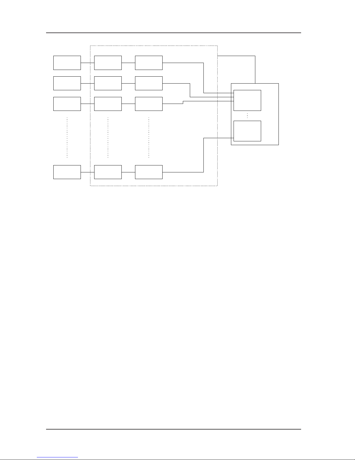
1.1.5. Multiplexing
The M1500 system can be fitted with a multistage multiplexing card enabling up to 16 analog
channels to be multiplexed onto a single analog input of an ADC. Thus using a typical 16 channel
ADC it is possible for the M1500 system to multiplex up to 256 analog channels into a single ADC.
This can be configured as a 64 channel system (one M1500 housing), a 128 channel system (two
M1500 housings) or a 256 channel system (four M1500 housings) by simple jumper selection.
1.1.6. Analog to Digital Converter (ADC)
The analog output, typically up to ± 10 volts, from a signal conditioner channel is converted to a
digital value by an ADC in the host computer. ADC’s for this type of application will typically be
16 channel and may be 12, 14 or 16 bit resolution for ISA or PCI configuration. The M1500
multiplexing card utilises the multiplex control outputs from an ADC to operate its internal
multiplexing, ensuring signal efficacy and compatibility with a large number of different
manufacturers’ products. The M1500 is physically configured for direct connection to the MicroStar
range of intelligent ADC’s. Connection to other manufacturers devices can be implemented easily.
For advice on suitable ADC’s the Micro Movements Application Support will be happy to assist
and Micro Movements can supply appropriate cables for instant connection to most available ADC’s.
1.1.7. High Speed Applications
The multiplexing of up to 256 channels into a single ADC by the M1500 system allows for space
efficient, cost effective implementation of high channel count applications. However, there are
technological limitations on the speed at which the signals can be multiplexed. Finite switching
times, settling times and digital transition delays exist in even the fastest available semiconductor
devices. This places a limitation of 1MHz maximum throughput rate on any multiplexed system whilst
retaining the accuracy of measurement. This means that for a system with 256 channels, sampling rates of
just under 4KHz on each channel are possible. With reduced numbers of channels (with ADC’s that
support equal mode multiplexing) the individual channel sampling rates can be increased.
Max. channel sampling rate = 1000 K samples per sec.
number of system channels
For ADC’s that only operate in burst mode then that is the maximum throughput rate and the maximum
channel sampling rate is: burst rate/256 samples per sec.
It is obvious from the above that in order to obtain higher individual channel sample rates it is necessary to
use more ADC’s. The M1500 system can be configured for Direct Output. In this instance the multiplexers
are bypassed so that individual signal conditioning channels are accessible in permanent real time. The
speed at which channels can be sampled is then only limited by the ADC performance. (See also Section
1.2.3.)

M1500 User Guide Section 1
© 2002 Micro Movements Ltd Ver. 2.0
Page: 4
Figure 1.3. Typical High Speed System with the M1500
As an example, using an M1500 Direct System and a MicroStar 4200 Series DAP board, it is possible to
obtain sampling rates of over 50KHz on each sensor channel. For technical advice on this or any other
application issue please contact Micro Movements Application Support.
1.2. Hardware Configuration
The basic configuration of any M1500 system is based on 4 channels of sensor input to any signal conditioning
module and up to 16 signal conditioning modules mixed in any order in an M1500 enclosure. This means
that 256 sensor inputs can be conditioned within a single enclosure. All enclosures have hard coding on
the backplane slots that interact with the RISC processor on each signal conditioning module. This enables
each module to know where it is located in an enclosure. The host computer can interrogate an enclosure
via the RS232 communication link and establish which type of module is inserted in each of the 16 slots.
Thus it is possible for the host computer to map signal conditioning functionality against location and
system address. Each enclosure has a built-in monitor module which provides visual indication of power
supply, multiplexer and RS232 status. The monitor unit also provides facility for a hardware trigger input
and a jumper selectable enclosure address for use in multi-enclosure systems. (See Section 2.2. for
settings).
TDCR SIGNAL
COND. FILTER
TDCR SIGNAL
COND. FILTER
TDCR SIGNAL
COND. FILTER
TDCR SIGNAL
COND. FILTER
M1500
COMPUTER
ADC
RS232
ADC

M1500 User Guide Section 1
© 2002 Micro Movements Ltd Ver. 2.0 Page: 5
1.2.1. Single Enclosure System
A single M1500 enclosure has the capacity for 16 modules, each of which contain circuitry to condition
signals from 4 sensors. Thus a single enclosure provides for up to 64 sensors.
Figure 1.4. Block Schematic of Single Enclosure M1500
The 16 slots in the enclosure can be populated with any combination of signal conditioning modules and
any number of slots can be left empty.
The normal presentation of the M1500 is as shown in Figure 1.6. With mounting ears for installation in a
19” rack. Without mounting ears but with a carrying handle for free-standing installation. The unit is
normally supplied with the power pack accepting a universal mains input.
Multiplexer
Signal Conditioner
Channel A
Signal Conditioner
Channel B
Signal Conditioner
Channel C
Signal Conditioner
Channel D
Sensor
1
Sensor
2
Sensor
3
Sensor
4
4-Channel Card fitted in Enclosure Slot 1
Signal Conditioner
Channel A
Signal Conditioner
Channel B
Signal Conditioner
Channel C
Signal Conditioner
Channel D
Sensor
5
Sensor
6
Sensor
7
Sensor
8
4-Channel Card fitted in Enclosure Slot 2
Signal Conditioner
Channel A
Signal Conditioner
Channel B
Signal Conditioner
Channel C
Signal Conditioner
Channel D
Sensor
61
Sensor
62
Sensor
63
Sensor
64
4-Channel Card fitted in Enclosure Slot 16
64 Analog sensor
channels
multiplexed onto
16 analog input
lines to ADC

M1500 User Guide Section 1
© 2002 Micro Movements Ltd Ver. 2.0
Page: 6
To cater for different user requirements, the enclosure is available in several optional configurations.
Figure 1.5. M1500 Open Frame Enclosure
The open frame enclosure is ideally suited to OEM installations for incorporation in 19" rack housings.
The backplane contains the necessary signal connectors for direct interface with a host PC and ADC, plus
a power connector for the necessary DC supplies of +5v, +15v, -15v and +24v. A separate power
supply for these DC voltages must be provided.
Figure 1.6. M1500 Closed Frame Enclosure
The closed frame enclosure is also suited to OEM installations but is designed to accept the Micro Movements
M1500 Power Pack. The Power Pack accepts a universal mains input with fusing, switching and filtering
and generation of the required DC voltages for operating the M1500 System. The Power Pack meets
EMC and LVD requirements.
The bench mounted enclosure is suited to single stand alone operations and includes the M1500 Power
Pack.
Figure 1.7. M1500 Bench Mounting Enclosure

M1500 User Guide Section 1
© 2002 Micro Movements Ltd Ver. 2.0 Page: 7
1.2.2. Multiple Enclosure System
The M1500 Enclosures can be grouped in blocks of 4 as shown below. A single enclosure has 16 slots
and thus 64 sensor channel capacity. Grouping 4 enclosures provides for 64 slots and a 256 sensor
channel capacity by using the ‘enclosure address’ facility on the Monitor.
Figure 1.8. Multiple M1500 Enclosure System
A single group of 4 enclosures has complete compatibility with most ADC cards, that support expansion
and a single RS232 control line. A second group of 4 enclosures (providing 512 sensor channels) will
require a second ADC card and a second RS232 port. The only limit to the total number of 4-enclosure
blocks is the capacity of the host computer and application software to support multiple ADC cards and
RS232 ports.
RS 232
RS 232
RS 232
RS 232
RS 232
16 Analog Lines
plus 4 mux
control lines
16 Analog
Output Lines
+ 4 x mux
16 Analog
Output Lines
+4 x mux
16 Analog
Output Lines
+ 4 x mux
16 Analog
Output Lines
+4 x mux
M1500 Enclosure
fitted with up to 16 Signal
Conditioner Cards
Up to 64 Sensor or
Signal Inputs
Enclosure 1
HOST COMPUTER
M1500 Enclosure
fitted with up to 16 Signal
Conditioner Cards
Up to 64 Sensor or
Signal Inputs
Enclosure 2
M1500 Enclosure
fitted with up to 16 Signal
Conditioner Cards
Up to 64 Sensor or
Signal Inputs
Enclosure 3
M1500 Enclosure
fitted with up to 16 Signal
Conditioner Cards
Up to 64 Sensor or
Signal Inputs
Enclosure 4
16
CHANNEL
ADC
RS 232
PORT
ADDITIONAL BLOCK OF FOUR
M1500 ENCLOSURES
Up to 256 Sensor or
Signal Inputs
16
CHANNEL
ADC
RS 232
PORT
16 Analog Lines
plus 4 mux
control lines
MUX
MUX
MUX
MUX

M1500 User Guide Section 1
© 2002 Micro Movements Ltd Ver. 2.0
Page: 8
1.2.3. Wide Bandwidth System
In some applications, the sampling rates discussed in Section 1.1.7. are not fast enough. The M1560
Universal Signal Conditioner, has a High Bandwidth Option of up to 100KHz (-3dB). This of course
requires sampling rates of 200K samples/sec per channel minimum which is incompatible with the use of
the multiplexer.
Figure 1.9. Direct Output Multiple M1500 System
The M1500 system can be factory configured for ‘Direct’ output as shown above, retaining all of the
programmability benefits and flexibility of function. In the signal conditioning housings the multiplexer
option is not fitted and special high bandwidth analog technology used to provide 4 conditioned, wide
bandwidth analog outputs from each card. This still allows up to 64 sensor channels in one enclosure but
requires 4 off 16 input ADC cards. The sampling rate is then determined solely by the ADC cards with no
other limitations.
Systems using the ‘Direct’ architecture can still be expanded as before and controlled by a single RS232
port for each block of 4 enclosures.
16 Analog
16 Analog
16 Analog
16 Analog
RS 232
RS 232
RS 232
RS 232
RS 232
16 Analog
Output Lines
16 Analog
Output Lines
16 Analog
Output Lines
16 Analog
Output lines
M1500 Enclosure
fitted with up to 16 Signal
Conditioner Cards
Up to 64 Sensor or
Signal Inputs
Enclosure 1
M1500 Enclosure
fitted with up to 16 Signal
Conditioner Cards
Up to 64 Sensor or
Signal Inputs
Enclosure 2
M1500 Enclosure
fitted with up to 16 Signal
Conditioner Cards
Up to 64 Sensor or
Signal Inputs
Enclosure 3
M1500 Enclosure
fitted with up to 16 Signal
Conditioner Cards
Up to 64 Sensor or
Signal Inputs
Enclosure 4 16
CHANNEL
ADC
RS 232
PORT
ADDITIONAL BLOCK OF FOUR
M1500 ENCLOSURES
Up to 256 Sensor or
Signal Inputs ADC
RS 232
PORT
HOST
COMPUTER
16
CHANNEL
ADC
16
CHANNEL
ADC
16
CHANNEL
ADC
ADC
ADC
ADC

M1500 User Guide Section 1
© 2002 Micro Movements Ltd Ver. 2.0 Page: 9
1.2.4. System Hierarchy
As described in previous sections, (see Figure 1.8.) the M1500 is structured around 256 sensor
channels feeding in to 64 Signal Conditioning cards, housed in 4 enclosures linked to 1 ADC card
and 1 RS232 port. Within this basic architecture, any number of the Signal Conditioning card or
enclosure elements may be omitted. For example for a 128 channel system, only 2 enclosures are
required or for a 32 channel system only 1 enclosure and 8 cards are required without any special
settings or alterations. Just connect up and use. The enclosures have fixed hardware addresses built in for
each card slot and a jumper settable enclosure address (see Section 2.2.) which enables total system
definition automatically. The M1500 enclosures can report back to the host PC which slots are populated
and which type of card is in each providing automatic system mapping.
Figure 1.10. M1500 System Channel Map
The addressing is in logical order and also controls the signal routing and multiplexing order.
ENCLOSURE
ADDRESS 1
SLOT 1
SLOT 2
SLOT 3
SLOT 4
SLOT 5
SLOT 6
SLOT 7
SLOT 8
SLOT 9
SLOT 10
SLOT 11
SLOT 12
SLOT 13
SLOT 14
SLOT 15
SLOT 16
ENCLOSURE
ADDRESS 2
ENCLOSURE
ADDRESS 3
ENCLOSURE
ADDRESS 4
CH1,CH2
CH3,CH4
CH65,CH66
CH67,CH68
CH129,CH130
CH131,CH132
CH193,CH194
CH195,CH196
CH5,CH6
CH7,CH8
CH69,CH70
CH71,CH72
CH133,CH134
CH135 CH136
CH197,CH198
CH199,CH200
CH9,CH10
CH11,CH12
CH73,CH74
CH75,CH76
CH137,CH138
CH139,CH140
CH201,CH202
CH203,CH204
CH13,CH14
CH15,CH16
CH77,CH78
CH79,CH80
CH141,CH142
CH143,CH144
CH205,CH206
CH207,CH208
CH17,CH18
CH19,CH20
CH81,CH82
CH83,CH84
CH145,CH146
CH147,CH148
CH209,CH210
CH211,CH212
CH21,CH22
CH23,CH24
CH85,CH86
CH87,CH88
CH149,CH150
CH151,CH152
CH213,CH214
CH215,CH216
CH25,CH26
CH27,CH28
CH89,CH90
CH91,CH92
CH153,CH154
CH155,CH156
CH217,CH218
CH219,CH220
CH29,CH30
CH31,CH32
CH93,CH94
CH95,CH96
CH157,CH158
CH159,CH160
CH221,CH222
CH223,CH224
CH33,CH34
CH35,CH36
CH97,CH98
CH99,CH100
CH161,CH162
CH163,CH164
CH225,CH226
CH227,CH228
CH37,CH38
CH39,CH40
CH101,CH102
CH103,CH104
CH165,CH166
CH167,CH168
CH229,CH230
CH231,CH232
CH41,CH42
CH43,CH44
CH105,CH106
CH107,CH108
CH169,CH170
CH171,CH172
CH233,CH234
CH235,CH236
CH45,CH46
CH47,CH48
CH109,CH110
CH111,CH112
CH173,CH174
CH175,CH176
CH237,CH238
CH239,CH240
CH49,CH50
CH51,CH52
CH113,CH114
CH115,CH116
CH177,CH178
CH179,CH180
CH241,CH242
CH243,CH244
CH53,CH54
CH55,CH56
CH117,CH118
CH119,CH120
CH181,CH182
CH183,CH184
CH245,CH246
CH247,CH248
CH57,CH58
CH59,CH60
CH121,CH122
CH123,CH124
CH185,CH186
CH187,CH188
CH249,CH250
CH251,CH252
CH61,CH62
CH63,CH64
CH125,CH126
CH127,CH128
CH189,CH190
CH191,CH192
CH253,CH254
CH255,CH256
M1500 SYSTEM CHANNEL MAP

M1500 User Guide Section 1
© 2002 Micro Movements Ltd Ver. 2.0
Page: 10
The 4-bit multiplexing control is provided by the ADC card and logically interpretted at each signal
conditioning card. Figure 1.11 shows the sensor channel encoding as it appears at the input of the ADC,
in relation to the multiplexer control signals.
Figure 1.11. M1500 Signal Multiplexing Protocol
The ‘position’ of a sensor within the encoding is determined entirely by the slot location in the enclosure. It
is not necessary to manually select the address of a card, it is performed automatically.
12345678910111213141516
Ch
1
Ch
2
Ch
3
Ch
4
Ch
5
Ch
6
Ch
7
Ch
8
Ch
9
Ch
10
Ch
11
Ch
12
Ch
13
Ch
14
Ch
15
Ch
16
Ch
17
Ch
18
Ch
19
Ch
20
Ch
21
Ch
22
Ch
23
Ch
24
Ch
25
Ch
26
Ch
27
Ch
28
Ch
29
Ch
30
Ch
31
Ch
32
Ch
33
Ch
34
Ch
35
Ch
36
Ch
37
Ch
38
Ch
39
Ch
40
Ch
41
Ch
42
Ch
43
Ch
44
Ch
45
Ch
46
Ch
47
Ch
48
Ch
49
Ch
50
Ch
51
Ch
52
Ch
53
Ch
54
Ch
55
Ch
56
Ch
57
Ch
58
Ch
59
Ch
60
Ch
61
Ch
62
Ch
63
Ch
64
Ch
65
Ch
66
Ch
67
Ch
68
Ch
69
Ch
70
Ch
71
Ch
72
Ch
73
Ch
74
Ch
75
Ch
76
Ch
77
Ch
78
Ch
79
Ch
80
Ch
81
Ch
82
Ch
83
Ch
84
Ch
85
Ch
86
Ch
87
Ch
88
Ch
89
Ch
90
Ch
91
Ch
92
Ch
93
Ch
94
Ch
95
Ch
96
Ch
97
Ch
98
Ch
99
Ch
100
Ch
101
Ch
102
Ch
103
Ch
104
Ch
105
Ch
106
Ch
107
Ch
108
Ch
109
Ch
110
Ch
111
Ch
112
Ch
113
Ch
114
Ch
115
Ch
116
Ch
117
Ch
118
Ch
119
Ch
120
Ch
121
Ch
122
Ch
123
Ch
124
Ch
125
Ch
126
Ch
127
Ch
128
Ch
129
Ch
130
Ch
131
Ch
132
Ch
133
Ch
134
Ch
135
Ch
136
Ch
137
Ch
138
Ch
139
Ch
140
Ch
141
Ch
142
Ch
143
Ch
144
Ch
145
Ch
146
Ch
147
Ch
148
Ch
149
Ch
150
Ch
151
Ch
152
Ch
153
Ch
154
Ch
155
Ch
156
Ch
157
Ch
158
Ch
159
Ch
160
Ch
161
Ch
162
Ch
163
Ch
164
Ch
165
Ch
166
Ch
167
Ch
168
Ch
169
Ch
170
Ch
171
Ch
172
Ch
173
Ch
174
Ch
175
Ch
176
Ch
177
Ch
178
Ch
179
Ch
180
Ch
181
Ch
182
Ch
183
Ch
184
Ch
185
Ch
186
Ch
187
Ch
188
Ch
189
Ch
190
Ch
191
Ch
192
Ch
193
Ch
194
Ch
195
Ch
196
Ch
197
Ch
198
Ch
199
Ch
200
Ch
201
Ch
202
Ch
203
Ch
204
Ch
205
Ch
206
Ch
207
Ch
208
Ch
209
Ch
210
Ch
211
Ch
212
Ch
213
Ch
214
Ch
215
Ch
216
Ch
217
Ch
218
Ch
219
Ch
220
Ch
221
Ch
222
Ch
223
Ch
224
Ch
225
Ch
226
Ch
227
Ch
228
Ch
229
Ch
230
Ch
231
Ch
232
Ch
233
Ch
234
Ch
235
Ch
236
Ch
237
Ch
238
Ch
239
Ch
240
Ch
241
Ch
242
Ch
243
Ch
244
Ch
245
Ch
246
Ch
247
Ch
248
Ch
249
Ch
250
Ch
251
Ch
252
Ch
253
Ch
254
Ch
255
Ch
256
MUX BIT 0
(LSB)
MUX BIT 0
(LSB)
MUX BIT 0
(LSB)
MUX BIT 0
(LSB)
TIME SLOT
ENCLOSURE
ADDRESS 0
ENCLOSURE
ADDRESS 1
ENCLOSURE
ADDRESS 2
ENCLOSURE
ADDRESS 3
ADC
INPUT
CHAN.
0
1
2
3
4
5
6
7
8
9
10
11
12
13
14
15

M1500 User Guide Section 1
© 2002 Micro Movements Ltd Ver. 2.0 Page: 11
1.2.5. Product Part Numbering
ENCLOSURES
M1500-M Open frame 64 channel chassis Multiplexed Output.
M1500-D Open frame 64 channel chassis Direct Output.
Options
M1519-A Enclosed housing for M1500-M or M1500-D.
M1519-B Integral Power Pack, Universal Mains Input (can only be fitted with
M1519-A or C options).
M1519-C Bench Top Housing for M1500-M or M1500-D.
SIGNAL CONDITIONERS
M1560-M 4 channel universal programmable amplifier Multiplexed Output.
M1560-D 4 channel universal programmable amplifier Direct Output.
M1588 4 channel straight-through card (Direct Output only).
M1588-A 4 channel straight-through card with switchable attenuators.
Options
M1560-B High Bandwidth option for M1560-D, covers all 4 channels (Specify
Bandwidth up to 100KHz).
M1590-01 LP Filter for M1560 (one required per sensor channel) Specify no. of
Poles, characteristic and cut off frequency.

M1500 User Guide Section 1
© 2002 Micro Movements Ltd Ver. 2.0
Page: 12
ACCESSORIES
C1504 In line attenuator plug for M1560 (Specify attenuation Max = 10:1).
C1508-1 Plug in calibration reference ¼ bridge strain gauge (Specify resistance
120W, 350W, 1KW, other).
C1508-2 Plug in calibration reference ½ bridge strain gauge (Specify resistance 120W,
350W, 1KW, other).
C1508-4 Plug in calibration reference full bridge strain gauge (Specify resistance 120W,
350W, 1KW, other).
C1509 Plug in calibration reference voltage source 1.000 volts.

M1500 User Guide Section 2
© 2001 Micro Movements Ltd Page: 13
Section 2
2.0. M1500 Series Enclosures.
2.1. Overview
The M1500 enclosures are available in Open Frame OEM, Closed Frame OEM and Benchtop
formats. In each of the physical presentations, the enclosures, the facilities and functions are identical
and can be supplied with either the Multiplexed Output or Direct Output options. See Section 1.2.
for details. The basic enclosures are supplied complete with a Monitor module in addition to 16
free signal conditioner slots. The M1515 Monitor module shown in Figure 2.1, provides jumper
selectable settings for the complete enclosure and its relative position in a multi-enclosure system.
The module also provides for hardware trigger inputs to be buffered and distributed in the required
format to the correct ADC in a system.
Figure 2.1. M1515 Monitor Module, Front Panel

M1500 User Guide Section 2
© 2001 Micro Movements LtdPage: 14
The Monitor module provides LED indications of the status of the following:
POWER
+15, -15, +5, TD. These are the internal DC power rails which should all be illuminated for correct
operation.
DIGITAL
D0, D1, D2, M4. These are bussed digital lines for special functions and should be extinguished
for normal operation.
MUX
0, 1, 2, 3. These are the buffered multiplex control lines from the ADC in the host computer. They
will only be illuminated when the ADC is gathering data. For Direct enclosures they should always
be extinguished.
COMMS
Rx, Tx. These indicate the transmit/receive status of the RS232 link with the host computer and
should intermittently illuminate during RS232 communication.
CHASSIS
CA0, CA1. These will illuminate according to internal jumper selection of chassis address. (See
sections 2.3. and 2.4.).
CA0 CA1 CHASSIS ADDRESS
OFF OFF 1
ON OFF 2
OFF ON 3
ON ON 4
Also on the front panel of the Monitor module, is an isolated BNC connector to enable the external
input of trigger signals (See section 2.2.).
2.2. External Triggering
The BNC connector on the front of the Monitor module permits the input of an external trigger.
The internal miniature 2 pin connector from the BNC can be connected to one of two positions on
the PCB (See section 2.3.) to accept either
a. A TTL or voltage pulse up to 24v (through optical isolator) or
b. A voltage free contact closure. (Can accept Normally Open or Normally Closed)
Jumper position allows the selection of trigger polarity. The bus-buffered trigger signal is then
routed to the connectors, on the rear of the enclosure, that interface with the ADC in the host

M1500 User Guide Section 2
© 2001 Micro Movements Ltd Page: 15
computer. This enables hardware triggering of the ADC which is required in some applications.
2.3. Jumper Configuration
Figure 2.2 shows the position of jumpers and settings on the monitor card which is included with all
enclosures.
Figure 2.2. View of Monitor Card
Figure 2.3. Position of jumpers and trigger type selection
TRIGGER TYPE
a. TTL or Pulse input up to 12 volts. Connect BNC to PL1 and ensure that RIO is removed.
b. Contact Closure. Connect BNC to PL2 and fit RIO = 10KOhms.
PL1/PL2 JP1/JP2 JP3-JP6
Sw1

M1500 User Guide Section 2
© 2001 Micro Movements LtdPage: 16
TRIGGER POLARITY
JP1 fitted - trigger to ADC normally low going high on trigger.
JP2 fitted - trigger to ADC normally high going low on trigger.
ENCLOSURE ADDRESS
ADDRESS POLE 1 POLE 2
1 OFF OFF
2 OFF ON
3 ON OFF
4 ON ON
For single enclosure applications, the Enclosure Address should be set to 1 (both poles OFF).
For multiple enclosure applications both Multiplex and Direct, the addresses must be set to unique
values for each enclosure within a 4 enclosure block. (See also section 1.2.2.).
2.4. Power Requirements
For open frame enclosures (see also section 1.2.). it is necessary to provide regulated smoothed DC
voltages. These should be current limited or fused.
+15 volts at 1.5 amps.
- 15 volts at 1.5 amps.
+ 5 volts at 1.5 amps
+24 volts at 2.0 amps.
Micro Movements Application Support can provide technical advice if required.
For closed frame OEM enclosures and Benchtop enclosures fitted with the Micro Movements M1500
Power Pack, the only supply required is AC Mains -
95 - 260 V ac 45 - 65 Hz 180 Watts
Table of contents