Inficon TC1000 User manual
OPERATING MANUAL
iina11e1-a (0604)
Catalog No.
551-005
TC1000
test chamber for hermetically sealed
parts

1-2
iina22e1 chapter 0.fm Operating Manual(0604)
0.1 Imprint
INFICON GmbH
Bonner Straße 498
50958 Köln
Germany
0.2 About these instructions
These instructions are intended for users of the TC1000.
The aim of the instructions is to provide you with a rapid introduction to assembly and
operation of the test chamber.
The structure of the instructions enables you to read the instructions from start to
finish, or only the sections relevant to you if you are already familiar with the unit. In
this case, a glossary is also available at the end of the document.
0.3 Content
0.1 Imprint 1-2
0.2 About these instructions 1-2
0.3 Content 1-2
1 Test chamber TC1000 1-1
1.1 Explanation of terms and symbols 1-1
1.2 Technical data 1-2
2 Structure of the TC1000 2-1
2.1 The test chamber 2-1
2.2 The test chamber on the leak detector 2-2
2.3 The test leak adapter 2-3
2.4 Scope of supply 2-4
2.5 Accessories 2-4
3 Operating the TC1000 3-1
3.1 Starting up the TC1000 3-1
3.1.1 Unpacking 3-1
3.1.2 Starting up 3-1
3.1.2.1 Mount the test chamber 3-1
3.1.2.2 Setting the Auto Leak Test operating mode 3-2
3.1.2.3 Setting the test chamber for the test 3-3
3.1.2.4 Calibrating the leak detector 3-4
3.1.2.5 Measuring mode 3-5
3.1.2.6 Cancelling the test mode 3-5
3.1.2.7 Interrupting and restarting the test mode 3-5
3.1.2.8 Shutting down 3-6
3.1.3 Removal 3-6
3.1.4 Packing 3-6
3.2 Settings in the Auto Leak Test menu 3-6

1-3
iina22e1 chapter 0.fm Operating Manual(0604)
3.2.1 Setting the measuring time 3-7
3.2.2 Setting the verification limit (Trigger level 1) 3-8
3.2.3 Serial errors when testing 3-8
3.2.4 Counting tested components 3-8
3.2.5 Reducing the helium substrate (reference measurement) 3-9
3.3 Maintenance schedule 3-9
3.4 Displaying and reading out the warning table 3-9
4 Further documents 4-1
4.1 Replacement parts list 4-1
4.2 Decontamination declaration 4-1

1-4
iina22e1 chapter 0.fm Operating Manual(0604)

Test chamber TC1000 1-1
iina11e1 chapter 1.fm Operating Manual(0604)
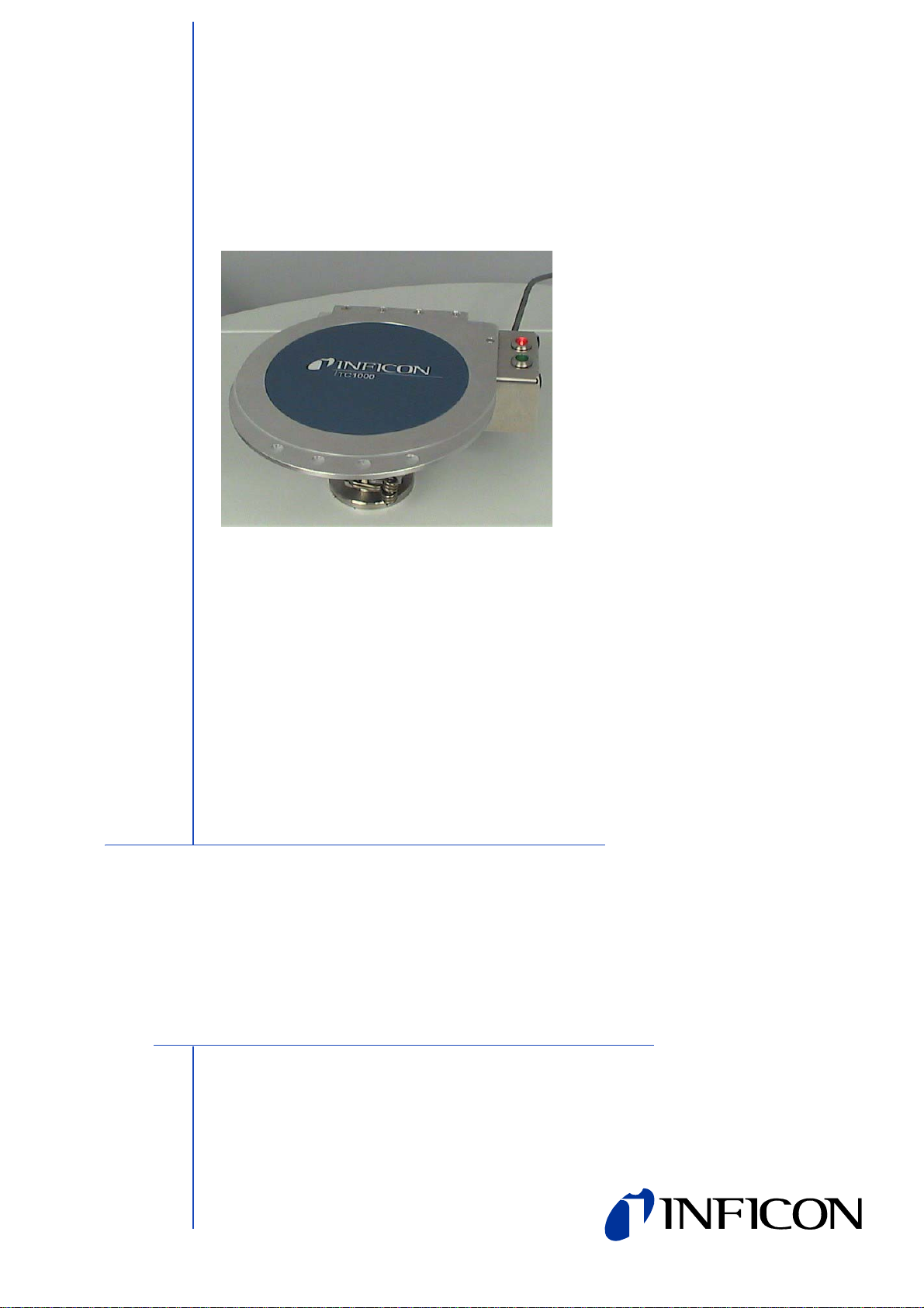
1 Test chamber TC1000
The TC1000 is a small vacuum chamber which allows you to carry out leak tests on
sealed, small solid bodies. These include e.g. quartzes, relays, sensors, ICs and
LEDs.
You can easily mount the test chamber on the leak detectors UL1000 and UL1000
Fab. It does not occupy much space thanks to its small size.
The test procedurefor the test chamber is very easy in conjunction with the INFICON
leak detectors. The test proceeds for the most part automatically.
You place the components in the test chamber and the process is activated by
closing the cover. Two large red and green light emitting diodes show you the results
of the test.
The procedure for dynamic calibration enables rapid and reliable testing of the
components.
1.1 Explanation of terms and symbols
Auto leak test
Refers to the operating mode of the leak detector UL1000 or UL1000 Fab, which
enables hermetically sealed components to be tested for leakproofness.
Dynamic calibration
The rise in a leakage rate signal is compared with the rise in the test leakage signal.
Increasing leakage rates can therefore be detected more rapidly.
Calibration and measurement have the same endurance. So the signals of the
underground that arouse because of a gas occupation of the surface can be better
suppressed.
ESD
Abbreviation for electrostatic discharge.
ESD mat
An ESD mat on the leak detector prevents electrostatic charges from discharging
e.g. onto components placed on it. The charge is removed via the mat.
(Coffee cup)
Indicates the button for the pause function.
1-2 Test chamber TC1000
iina11e1 chapter 1.fm Operating Manual(0604)
Warning triangle
Indicates a upcoming warning message which you can see by pressing the button.
1.2 Technical data
Diameter 130 mm
Depth 40 mm
Volume approx. 430 cm³
Weight 2.7 kg
Connecting flange DN 25 KF

Structure of the TC1000 2-1
iina11e1 chapter 2.fm Operating Manual(0604)
2 Structure of the TC1000
2.1 The test chamber
Abb. 2-1 The closed test chamber
Item Description
1 Cover The cover of the test chamber has a floating
mounting. It rests securely on the sealing lock.
2 Connecting cable The electrical connection to the leak detector.
3 Red light emitting diode The red light emitting diode lights up if a leak is
verified which is greater than the trigger
threshold set.
4 Green light emitting diode The green light emitting diode lights up if a leak
is verified which is less than the trigger
threshold set.
5 ESD bracelet connection
on the right of the test
chamber
You can connect the ESD bracelet to this
pushbutton.
Potential static charges are discharged via a
ESD bracelet. This prevents the components
you are testing from becoming damaged.
6 Handle area Hold the cover here for opening and closing.
2-2 Structure of the TC1000
iina11e1 chapter 2.fm Operating Manual(0604)
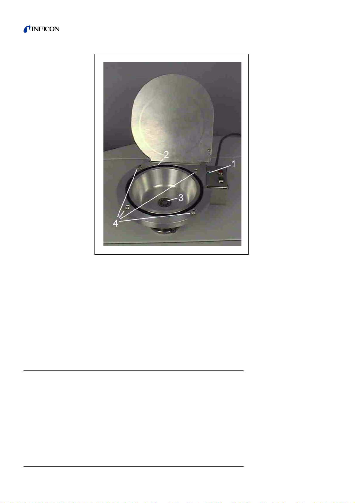
2.2 The test chamber on the leak detector
The test chamber can preferably be operated on the INFICON leak detectors
UL1000 or UL1000 Fab (software version 4.0 or higher).
In the following we describe use of the test chamber on a UL1000 Fab.
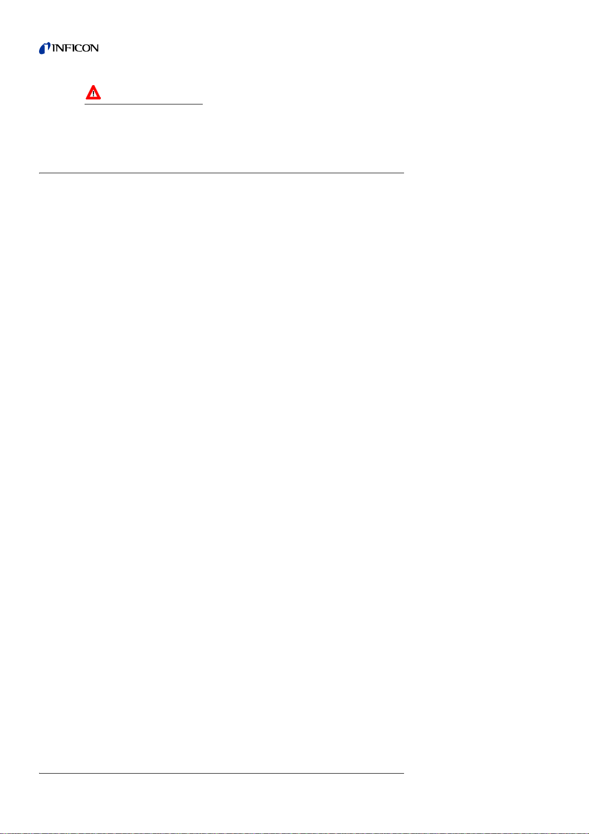
Abb. 2-2 The open test chamber
Item Description
1 Proximity switch Ifyou closethecover, you activate the evacuation
process via the proximity switch.
2 O-ring The sealing ring seals the test chamber against
the cover and can easily be replaced.
3 Screen The screen prevents components from falling into
the connecting flange.
4 Bore holes You can fasten the test chamber on a work table.
The bore holes are already provided for this.
Structure of the TC1000 2-3
iina11e1 chapter 2.fm Operating Manual(0604)
The test chamber is mounted on the leak detector with a tightening ring
You can find the instructions for this in Section 3.1.2.1, Removal.
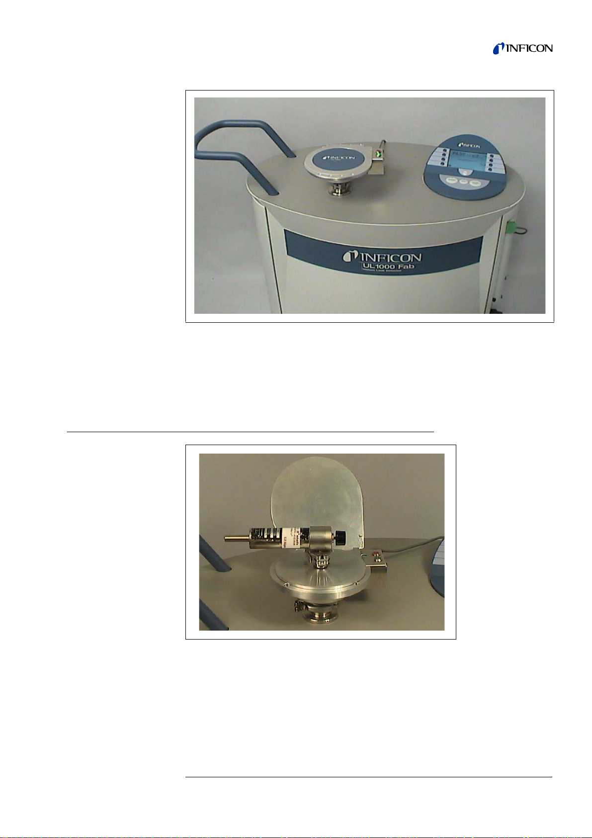
2.3 The test leak adapter
If you carry outan external calibration,you will needan adapter cable anda test leak,
e.g. leak test TL7.
Section 3.1.2.4, Calibrating the leak detector describes how to calibrate the leak
detector.
Fig. 2-3 Mounted on the leak detector
Abb. 2-4

2-4 Structure of the TC1000
iina11e1 chapter 2.fm Operating Manual(0604)
2.4 Scope of supply
The delivery comprises:
• the test chamber TC1000,
• an ESD bracelet,
• the operating instructions for the unit (iina11d1)
2.5 Accessories
Catalogue number
• ESD mat 551-002
• Test leak adapter 200 00 1797
• Test leak TL 7 (leakage rate in the range10-7mbar l/s) 14210
• Test leak TL 8 (leakage rate in the range10-8mbar l/s) 16557
• Test leak TL 8 with DKD calibration 15593
• Test leak TL 9 (leakage rate in the range10-9mbar l/s) 14408
Operating the TC1000 3-1
iina11e1 chapter 3.fm Operating Manual(0604)
3 Operating the TC1000
3.1 Starting up the TC1000
3.1.1 Unpacking
1Now remove the plastic casing in which the TC1000 and accessories are packed.
2Check the delivery for completeness. The scope of supply are listed in Section 2.4.
3Keep the plastic casing and packaging so that you can store the test chamber in it
during periods when you are not using the test chamber.
3.1.2 Starting up
3.1.2.1 Mount the test chamber
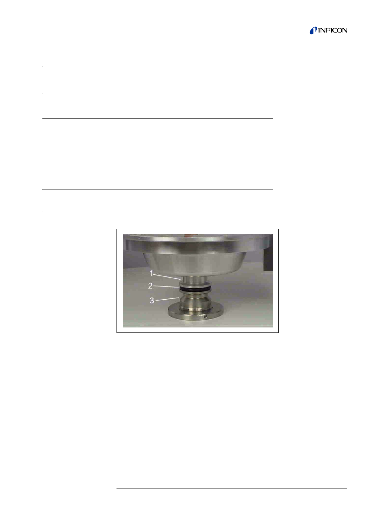
1Place the test chamber on the inlet flange of the leak detector.
Fig. 3-1
Item Description
1 TC1000
2 Centerring ring
3Flange
3-2 Operating the TC1000
iina11e1 chapter 3.fm Operating Manual(0604)
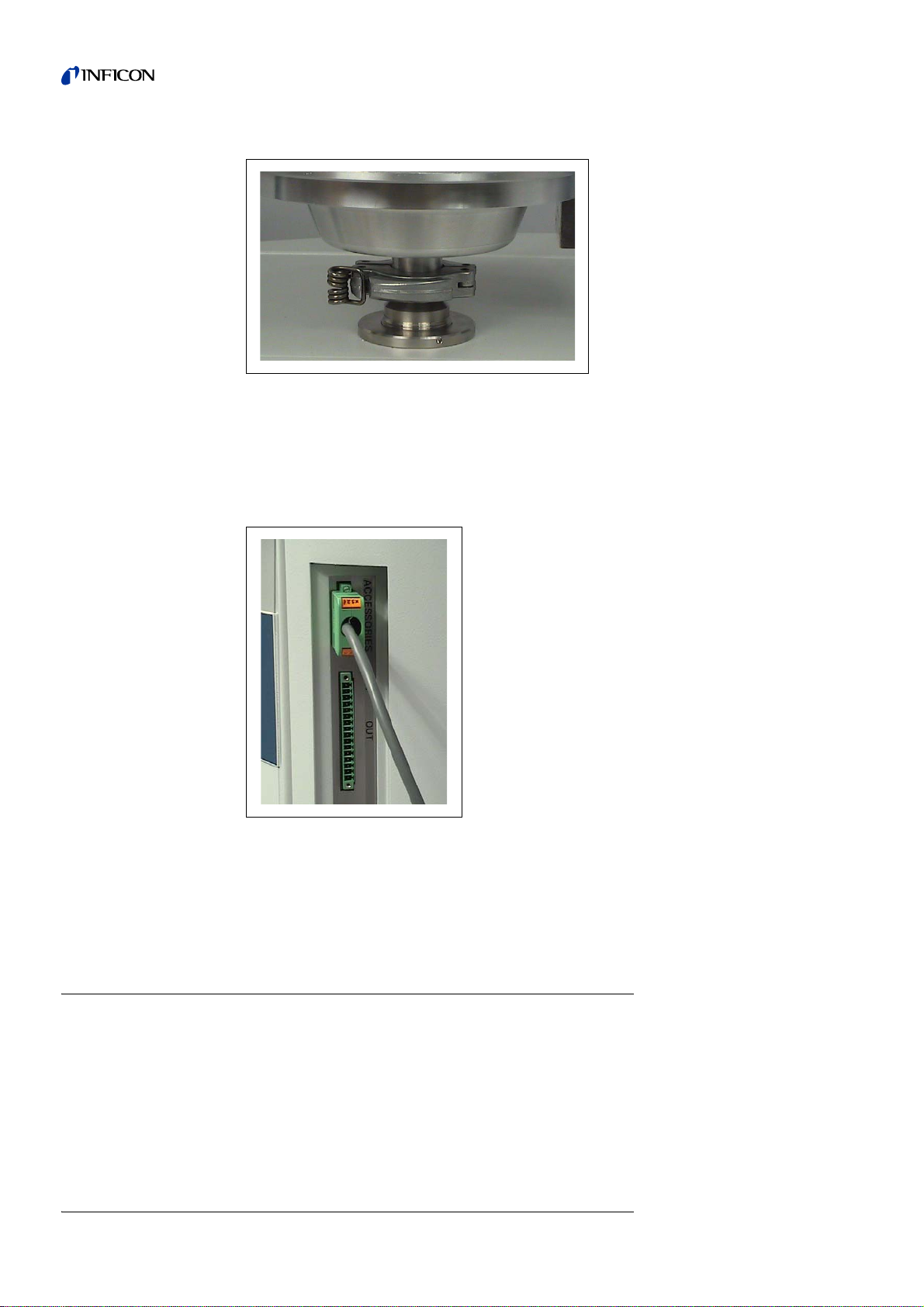
2Connect the test chamber to the leak detector by mounting a tightening ring.
The test chamber is mounted on the unit. You can now establish the electrical
connection between the test chamber and the leak detector.
3Connect the cable to the Accessories socket of the leak detector UL1000 or
UL1000 Fab.
4Call up the Auto Leak Test submenu in order to start the automatic test sequence.
You can find further information on the Auto Leak Test operating mode in Section
3.1.2.2.
3.1.2.2 Setting the Auto Leak Test operating mode
1Switch on the leak detector.
2Press the Menu button.
The Display main menu appears on the screen of the leak detector.
Fig. 3-2
Fig. 3-3

Operating the TC1000 3-3
iina11e1 chapter 3.fm Operating Manual(0604)
3Press the following buttons in the correct sequence in order to prepare the leak
detector for operation of the test chamber.
MAIN MENU →MODE →AUTO LEAK TEST →OK
When first setting the Auto Leak Test operating mode, the leak detector refers to the
menu AUTO LEAK TEST SETTINGS.
4If you set the default settings (OK), you will be taken to operation. If you abort the
process (Cancel), you will leave the operating mode again at this point.
3.1.2.3 Setting the test chamber for the test
1When the leak detector isnot set to AUTO LEAK TEST menupleasepressthe following
buttons in succession:
MENU →SETTINGS →VACUUM SETTINGS →AUTO LEAK TEST SETTINGS
2The Auto Leak Test Settings menu now appears.
To be able to work in measuring mode, you need to set at least the measuring time
and the rejection rate.
Fig. 3-4

3-4 Operating the TC1000
iina11e1 chapter 3.fm Operating Manual(0604)
3Now set the measuring time and rejection rate:
Setting the measuring time:
1Press the Measuring Time button.
2Set the measuring time you require and confirm with OK.
Setting the rejection rate:
3Press the Trigger Level button
4Set the leakage rate you require and confirm with OK.
You can find more detailed information on setting the test chamber for the test in
Section 3.2.
3.1.2.4 Calibrating the leak detector
Please calibrate the leak detector every now and then. Especially when it did not run
for a longer time.
When you set or change the measuring time the leak detector requests you to
calibrate.
Calibrating with the internal test leak:
1Press the CAL button.
You have now started the calibration.
2Follow the instructions on the display.
Calibrating with the external test leak:
1Connect a test leak with manual valve to the adapter cover.
Open the cover of the test chamber for this and place the adapter cover on it.
Fig. 3-5

Operating the TC1000 3-5
iina11e1 chapter 3.fm Operating Manual(0604)
2Press the CAL button.
You have now started the calibration.
3Follow the instructions on the display.
3.1.2.5 Measuring mode
1Place the component in the test chamber.
2Close the cover of the test chamber.
The test mode is automatically started.
The device ends the test after the set measuring time has expired:
If the unit has completed the test, it indicates whether the component has passed the
test (PASS) or whether leaks are present in the components (FAIL).
3.1.2.6 Cancelling the test mode
1Press the STOP button.
The leak detector interrupts the test mode.
The leak detector does not show any result.
3.1.2.7 Interrupting and restarting the test mode
1Press the button next to the pictogram of the coffee cup.
Fig. 3-6 Trigger level set to 1x10⁻⁹, no leak found
Fig. 3-7 Trigger level set to 1x10⁻⁹, a leak found

3-6 Operating the TC1000
iina11e1 chapter 3.fm Operating Manual(0604)
The leak detector is now in an operation-ready state.
2Press the Restart button.
The operation is started again.
3.1.2.8 Shutting down
1Ventilate the test chamber and
2press the mains switch.
This switches off the leak detector.
Notice We recommend to evacuate thetest chamber befor you switch off the leak
detector. So you can avoid defilement.
If the test chamber is to remain depressurised after switching off the leak detector:
1Press the Coffee Cup button.
3.1.3 Removal
You can remove the test chamber if you have switched off the leak detector.
1Loosen the tightening ring.
2Take the test chamber off the flange and remove the o-ring.
You can find photographs, in reverse order, in Section 3.1.2.1, Mount the test
chamber.
3.1.4 Packing
1Take out the cardboardbox with the padding paper which was provided with the test
chamber.
2Pack the TC1000 and accessories in the plastic casing.
3Place the TC1000 in the padded cardboard box.
3.2 Settings in the Auto Leak Test menu
You can access the AUTO LEAK TEST SETTINGS menu at any time from the measuring
mode.
MAIN MENU →SETTINGS →VACUUM SETTINGS →AUTO LEAK TEST SETTINGS

Operating the TC1000 3-7
iina11e1 chapter 3.fm Operating Manual(0604)
Several settings are available for selection.
1Select the setting you require and confirm with OK.
The display then jumps back to the superior menu.
3.2.1 Setting the measuring time
1Proceed as follows in the menu so as to be able to set the measuring time:
MAIN MENU →SETTINGS →VACUUM SETTINGS →AUTO LEAK TEST SETTINGS →
MEASURING TIME
2Enter the required measuring time.
A measurement lasts between 1 second and 30 minutes, depending on how you
have previously set the leak detector.
The measurement depends on three factors: the volume of the test chamber, the
volume of the components being tested and the rejection leakage rate (trigger level).
If you change the measuring time, the unit could require a calibration.
You can find further information at 3.1.2.4, Calibrating the leak detector.
Examples of settings for
time
The INFICON test chamber was used with a content of 430 cm³ for the settings in
these examples.
Fig. 3-8
Item Description Item Description
1 Back 5 Part number
2 Measuring time 6 Reference measurement
3 Trigger level 1
4 Serial error message
Rejection rate Measuring time (recommended)
10E-5 2 seconds
10E-6 2 seconds
10E-7 2 seconds

3-8 Operating the TC1000
iina11e1 chapter 3.fm Operating Manual(0604)
You have now specified the measuring time.
3.2.2 Setting the verification limit (Trigger level 1)
1Proceed as follows in the menu so as to be able to set the verification limit:
MAIN MENU →SETTINGS →VACUUM SETTINGS →AUTO LEAK TEST SETTINGS →
TRIGGER LEVEL 1
2Enter the required verification time.
3Press the button OK.
To test components, the verification limit (trigger level) can be set from 10E-1 to
10E-9 mbar l/s.
You have now specified the verification limit.
3.2.3 Serial errors when testing
1Proceed as follows in the menu in order to test the measuring accuracy:
MAIN MENU →SETTINGS →VACUUM SETTINGS →AUTO LEAK TEST SETTINGS →
SERIAL ERROR MESSAGE
You can specify the number of leaking components occurring in succession during a
test after which a serial error message is indicated by the leak detector.
2You can select between 1 to 9 messages with defective components or deactivate
the function.
You can typically enter the number 3.
The leak detector identifies 3 components in succession as defective in the following
tests.
3The leak detector prompts you to do a reference measurement.
You can find more detailed information in Section 3.2.5.
3.2.4 Counting tested components
1Proceed as follows in the menu in order to give a number to the components you are
testing.
MAIN MENU →SETTINGS →VACUUM SETTINGS →AUTO LEAK TEST SETTINGS →PART
NUMBER
2Enter the number of the first component. Afterwards the unit automatically counts up
the number of tested components.
The unit then counts the tested components and displays the result.
10E-8 >5 seconds
10E-9 >10 seconds*
* We recommend an external calibration with a test
leak TL9 (10E-9).
Rejection rate Measuring time (recommended)

Operating the TC1000 3-9
iina11e1 chapter 3.fm Operating Manual(0604)
3.2.5 Reducing the helium substrate (reference
measurement)
The leak detector responds to helium. This is to verify the helium which emerges
from openings in the components. After a series of tests, there might be so much
helium in the unit that the leak detector responds to this with an error message. It
does not then verify the helium which emerges from the component, but instead the
helium which is located in the unit for other reasons.
1Proceed as follows in the menu in order to reduce the helium substrate:
MAIN MENU →SETTINGS →VACUUM SETTINGS →AUTO LEAK TEST SETTINGS →
REFERENCE TEST
After a series error message has come up you can start the reference measurement
from the stand by display. Press the button reference measurement.
2Follow the instructions on the display
3and press the OK button.
The leak detector pumps the test chamber 3 times empty and then ventilates again
each time. The unit is calibrated internally.
After the reference test, the leak detector measures the helium substrate and
subtracts the value from the measurements which are carried out.
3.3 Maintenance schedule
The test chamber does not require maintenance.
O-ring
Check occasionally whether the o-ring is damaged. If necessary, replace it.
Cleaning
1Clean the test chamber with alcohol.
2Pump the chamber 3 to 4 times after the cleaning. In this way you can remove
residual vapours from the surface.
3.4 Displaying and reading out the warning table
A warning triangle appears on the display if faults occur.
If you wish to read out the fault display,
1press the button next to it.
2Follow the instructions to rectify the warning.

3-10 Operating the TC1000
iina11e1 chapter 3.fm Operating Manual(0604)
This manual suits for next models
1
Table of contents
Other Inficon Test Equipment manuals

Inficon
Inficon 122 20 Quick guide

Inficon
Inficon ULTRATEST UL3000 Fab PLUS User manual

Inficon
Inficon FTC3000 Quick guide

Inficon
Inficon TGF10 User manual

Inficon
Inficon TL3-5 User manual

Inficon
Inficon 12329 Quick guide

Inficon
Inficon VORTEX User manual

Inficon
Inficon E-Check Quick guide

Inficon
Inficon MPG400 User manual

Inficon
Inficon MCT150 User manual


Popular Test Equipment manuals by other brands


Anritsu
Anritsu Site Master S330A user guide

Softing
Softing CableMaster 210 quick start guide

Aimco
Aimco AUDITOR AUET quick start guide

Fluke
Fluke 80PK-10 instruction sheet

EA Technology
EA Technology UltraTEV Monitor operating manual

Keysight Technologies
Keysight Technologies 85058E User's and service guide