Presys TA-1200PLAB User manual
Q
Y
U
T
A
L
I
E
N
T
M
S
E
Y
G
S
A
T
N
E
A
M
M
Reference
Temperature Calibrator
TA-1200PLAB
®
EM0356-02
Technical Manual
presys
presys

Note: changes can be introduced to the instrument, altering the information contained in
this technical manual.
The warranty conditions are available in our sites:
www.presys.com.br/warranty
presys

PRESYS Instruments TA-1200PLAB
EM0356-02
Table of Contents
1 - Introduction ...................................................................................................................1
1.1 - Technical Specifications...........................................................................................3
1.1.1 - Input Technical Specifications...........................................................................3
1.1.2 - Special Software Features................................................................................4
1.2 - Order Code...............................................................................................................4
1.3 - Accessories ..............................................................................................................5
1.4 - Initial Usage..............................................................................................................6
1.4.1 - Mounting the Insert in the Calibrator - Vertical Model......................................6
1.5 - Parts Identification....................................................................................................7
2 - Calibrator Operation.....................................................................................................8
2.1 - Calibrator Menu........................................................................................................9
2.1.1 - Probe Reference..............................................................................................10
2.1.2. - Input Connections Diagrams..........................................................................14
2.1.3 - Saving Current Configuration (Memory Manager)..........................................14
2.2 - Data-Logger............................................................................................................14
2.3 - Help Desk...............................................................................................................16
3 - SETTINGS.....................................................................................................................16
3.1 - Date and Time........................................................................................................16
3.2 - Network...................................................................................................................16
3.3 - Services..................................................................................................................17
3.3.1 - Built-in Web Server..........................................................................................17
3.3.2 - Remote Access - VNC.....................................................................................18
3.3.3 - Command List SCPI........................................................................................18
3.4 - System....................................................................................................................21
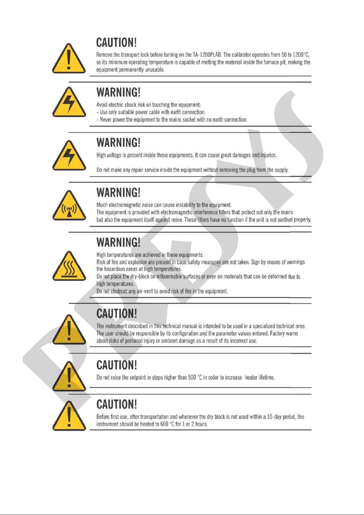
4 - Safety Instructions......................................................................................................22
5 - Recommendations as regards Accuracy of Measurements .................................22
6 - Calibration (Adjustment)............................................................................................23
6.1 - Input Calibration .....................................................................................................23
6.2 - Probe Calibration....................................................................................................24
6.3 - PID Control Parameters.........................................................................................24
6.4 - Axial Homogeneity Adjustment..............................................................................25
presys

PRESYS Instruments TA-1200PLAB
Page 1
1 - Introduction
TA-1200PLAB
The TA-1200PLAB Calibration Furnace is state-of-the-art in the manufacture and
performance of high temperature furnaces for calibration of thermocouples.
Its design privileges fundamental technical characteristics in temperature
measurement and which are usually the predominant sources of uncertainty in a
calibration. Thus it has been designed and tested according to international standards to
perfect the following characteristics:
I. Low axial and radial gradients due to the use of differentiated heaters distributed
along the thermal well in order to minimize losses at the ends of the insert and to
extend the temperature constant region called the measurement zone.
II. High immersion of the sensors to be compared - it has an insert with 250 mm of
immersion in the conductive part and about 70 mm in the insulation part, making
about 320 mm of total immersion of the sensors, which minimizes heat losses by
conduction the rod.
III. High thermal stability or thermal inertia - The 400 mm long insert has a large mass
volume and stabilizes any temperature fluctuation due to insertion or removal ofthe
sensor in the insert.
The entire calibrator is enclosed in a thermal shield for operator and laboratory
protection from the high temperatures generated. Thus in an eventual blackout of energy
the cooling of the furnace happens naturally and surely.
Temperature Advanced Calibrator TA-1200PLAB generates temperature in the
insert in order to calibrate thermocouples. Besides providing high accuracy temperature
values, it also allows the measurement of signals generated by the thermo-element which
is being calibrated. This is possible due to an embedded calibrator specific for this type of
signal. Thus, they incorporate the functions of dry block, standard thermometer and
calibrator for TC.
presys

PRESYS Instruments TA-1200PLAB
Page 2
•TA-1200PLAB calibrator model generates temperatures from 50 ºC (122 ºF) to
1200 ºC (2192 ºF).
•Presents 02 inputs for thermocouples that can follow the parameterization of ITS90
or standard tables.
•Carries out completely automatic calibrations with or without the use of a computer.
•Accuracy to ± 2.5 ºC, stability of 0.01 ºC and resolution of 0.01 ºC.
The calibrator provides an input for an external probe to perform the temperature
measurement from a standard sensor (optional) inserted in the same measuring zone of
the sensor to be calibrated. The standard sensor calibration curve follows the
parameterization of ITS-90.
It presents a wide variety of programming resources, allowing the performance of
automatic calibrations. In this case, the sensor is placed in the insert and its electrical
terminals are connected to the embedded calibrator. The operator defines the calibration
points and the number of repetitions (task), then the process is started and all the
sequence is automatically accomplished. After completing the task, a Calibration Report
is issued and it can be printed directly in a USB connected printer or can be generated as
a PDF document.
TA-1200PLAB has also many other features, such as:
•Built in Web Server, Ethernet communication.
•USB port for software/firmware upgrade.
•The electric signal calibrator is independent from the dry block function.
•Display indication when the temperature reaches the desired value.
•5.7 inches touch screen display that eases the operation and configuration of the
calibrator.
•Thermocouple reading scaled to ITS-90 or IPTS-68.
•Independent circuit for over-temperature protection and safety.
•Insert to choose and test leads included.
presys

PRESYS │ Instruments TA-1200PLAB
Page 3
1.1 - Technical Specifications
TA-1200PLAB
Operating Range
50 to 1200 °C (122 to 2192 °F)
Power Supply
230 Vac 50/60Hz
Resolution
0.01 ºC or 0.01 ºF
Display Accuracy
± 2.5 °C
Stability
± 0.1 ºC
Power Consumption
2500 W
Stabilization Time
1 h
Heating Rate
± 6 ºC / min
Cooling Rate
10 h (1100 ºC to 200 ºC)
Calibration Volume
∅34 mm / 300 mm depth (immersion)
Radial Uniformity
± 0.1 ºC (for metallic insert)
Axial Uniformity (40 mm):
Axial Uniformity (100 mm):
± 0.20 full range
± 0.35 full range
Dimensions (H,W,D)
Horizontal Model:
600 mm x 470 mm x 450 mm
Weight
43.0 kg
Warranty
1 year
1.1.1 - Input Technical Specifications
Ranges
Resolution
Accuracy
Remarks
millivolt
0 to 70 mV
0.0001 mV
± 0.005 % FS
Rinput > 10 MΩ
TC-J
-210 to 1200 ºC / -346 to 2192 ºF
0.01 ºC / 0.01 ºF
± 0.10 ºC / ± 0.20 ºF
IEC-60584
TC-B
50 to 250 ºC / 122 to 482 ºF
250 to 500 ºC / 482 to 932 ºF
500 to 1200 ºC / 932 to 2192 ºF
1200 to 1820 ºC / 2192 to 3308 ºF
0.01 ºC / 0.01 ºF
0.01 ºC / 0.01 ºF
0.01 ºC / 0.01 ºF
0.01 ºC / 0.01 ºF
± 1.25 ºC / ± 2.50 ºF
± 0.75 ºC / ± 1.50 ºF
± 0.50 ºC / ± 1.00 ºF
± 0.35 ºC / ± 0.70 ºF
IEC-60584
TC-S
-50 to 300 ºC / -58 to 572 ºF
300 to 1760 ºC / 572 to 3200 ºF
0.01 ºC / 0.01 ºF
0.01 ºC / 0.01 ºF
± 0.50 ºC / ± 1.00 ºF
± 0.35 ºC / ± 0.70 ºF
IEC-60584
TC-L
-200 to 900 ºC / -328 to 1652 ºF
0.01 ºC / 0.01 ºF
± 0.10 ºC / ± 0.20 ºF
DIN-43710
TC-C
0 to 1500 ºC / 32 to 2732 ºF
1500 to 2320 ºC / 2732 to 4208 ºF
0.01 ºC / 0.01 ºF
0.01 ºC / 0.01 ºF
± 0.25 ºC / ± 0.50 ºF
± 0.35 ºC / ± 0.70 ºF
W5Re / W26Re
W5Re / W26Re
TC-Au-Pt
0 to 500 °C/ 32 to 932 °F
500 to 1000 °C/ 932 to 1832 °F
ºC / 0.01 ºF
0.01 ºC / 0.01 ºF
± 0.09 ºC / ± 0.12 ºF
± 0.06 ºC / ± 0.12 ºF
ASTM E1751
FS = Full Scale
presys
PRESYS Instruments TA-1200PLAB
Page 4
The thermocouple specifications are valid for standard curve.
Accuracy values are valid within one year and temperature range of 20 to 26 °C. Outside
these limits add 0.001 % FS / °C taking 23 °C as the reference temperature. For
thermocouples, using the internal cold junction compensation add a cold junction
compensation error of ± 0.2 °C or ± 0.4 °F max.
1.1.2 - Special Software Features
- Memory Manager: stores configuration types predefined by the user.
- Data Logger: monitoring of input or output signals, storage and visualization of data in
chart or table.
- Help Desk: storage and viewing videos and documents on the calibrator screen.
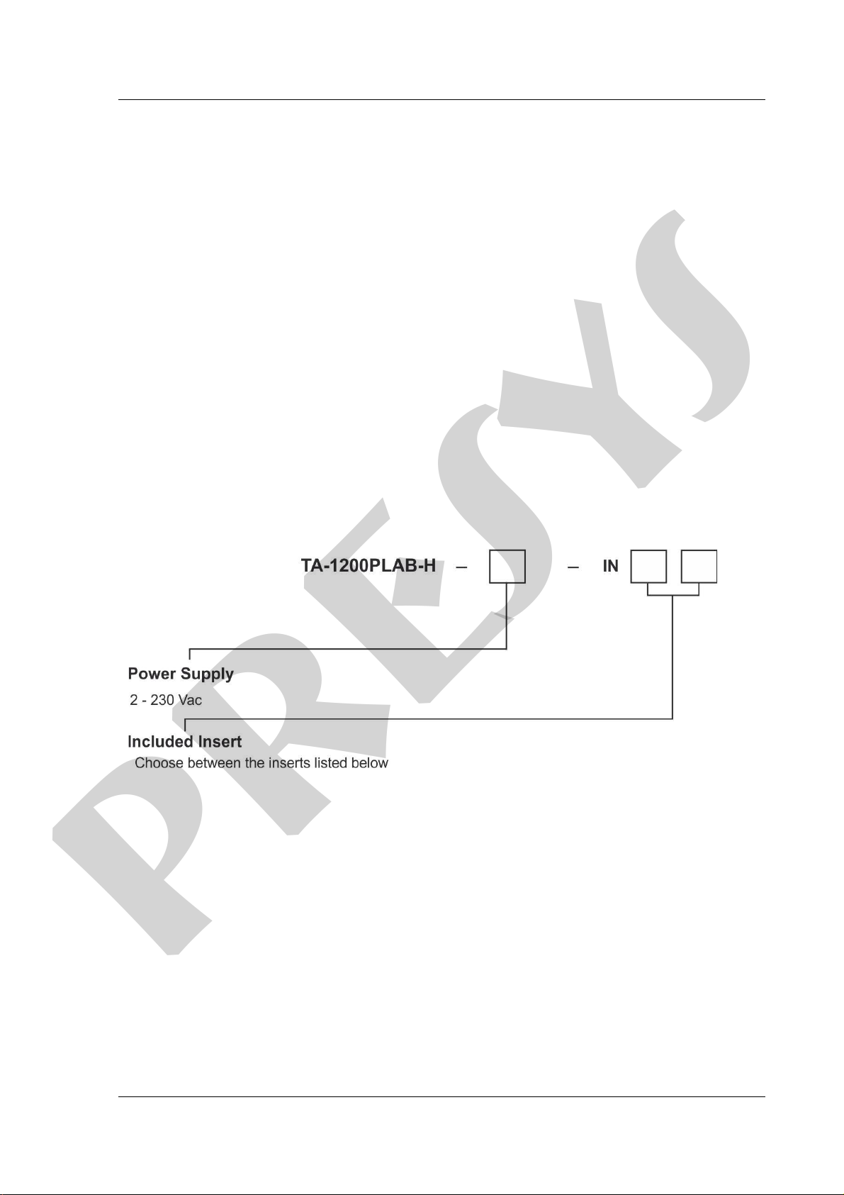
1.2 - Order Code
Notes:
* Changes can be introduced in the instrument, altering specifications in this manual.
presys

PRESYS │ Instruments TA-1200PLAB
Page 5
1.3 - Accessories
- Metallic Insert:
Inserts Holes
ORDER CODE
TA-1200PLAB-H
IN01
1 x 3/4"
06.04.0075-00
IN02
1 x 1/2"
06.04.0076-00
IN03 1 x 6.0mm and 3 x 1/4" 06.04.0077-00
IN04
3 x 6.0mm and 1 x 1/4"
06.04.0078-00
IN05
4 x 6.0mm
06.04.0079-00
IN06
2 x 6.0mm and 2 x 1/4"
06.04.0080-00
IN07 1 x 6.0mm, 1 x 8.0mm and 1 x 3/8" 06.04.0081-00
IN08 1 x 6.0mm, 1 x 3.0mm and 2 x 1/4" 06.04.0082-00
IN09
Without hole, to be drilled by the client
06.04.0086-00
IN10
Others, under ordering
06.04.0084-00
Note: When asked, the calibration certificate will be provided for the first insert ordered.
Fig. 01 - Inserts
Ceramic Insert:
Inserts
Holes
IN1C
2x 3.5 mm, 2x 4.0 mm, 2x6.0 mm and 2x 1/4" (Alumina)
IN2C 1x 1/4" and 6x 7.0 mm (Alumina)
IN10
under ordering (Alumina)
presys
PRESYS Instruments TA-1200PLAB
Page 6
1.4 - Initial Usage
Identify if the following parts are present:
•TA-1200PLAB Calibrator;
•Metallic or ceramic insert;
•Bottom insulation of the insert (only one central hole);
•Top insulation of the insert (same holes of the metallic insert);
In the core of the dry block TA-1200PLAB there is a ceramic tube. Therefore, for
safety purposes, the insert and the insulators are separated. A support is sent to protect
the block. Remove the screws indicated by the arrows and remove the support. Store it
and use it whenever you need to transport the dry block.
Finish the mounting using the grounding pin board and the frame with a grid.
1.4.1 - Mounting the Insert in the Calibrator - Vertical Model
To mount the insert inside the Calibrator, proceed as follows:
I) Place the Calibrator in its definitive place and spacing more than 25 cm from nearby
walls.
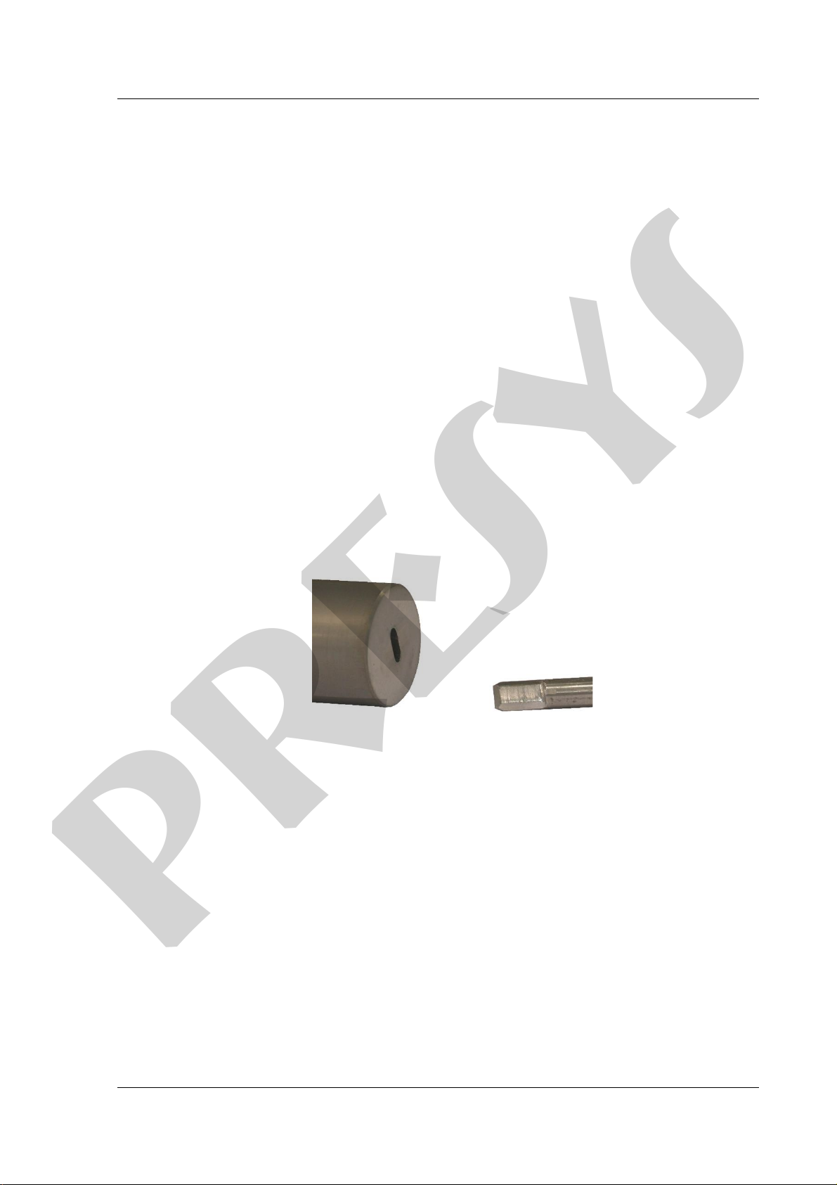
II) Observe in the following figure the type of gap in the lower part ofthe metallic insert
with the type offittingin the grounding pin inside the furnace well. Note: The ceramic
insert does not have this gap.
Fig. 02 - Insert Background (Horizontal Model)
I) Screw or fix the extractor to the insert and holding the insert with both hands slowly
insert the heavy insert into the very fragile ceramic well. Orient yourself by the mark
of a point on the insert to keep this side up.
II) It is essential to ensure an effective grounding if the gap coincides with its fitting on
the grounding pin. It is necessary to repeat the movement of the insert back and
forth a few times in the well to hear the click noise between the insert and the
grounding pin. Unscrew the extractor.
III) Then insert the top insulation in line with the holes in the insert. Use a ceramic rod
for it.
IV) Finally, tighten the metal cap by aligning it with the other holes in the top of the
calibrator well.
Note that the sensors to be tested must pass through the insulation and deepen
inside the metal insert to obtain a correct temperature measurement.
presys
PRESYS │ Instruments TA-1200PLAB
Page 7
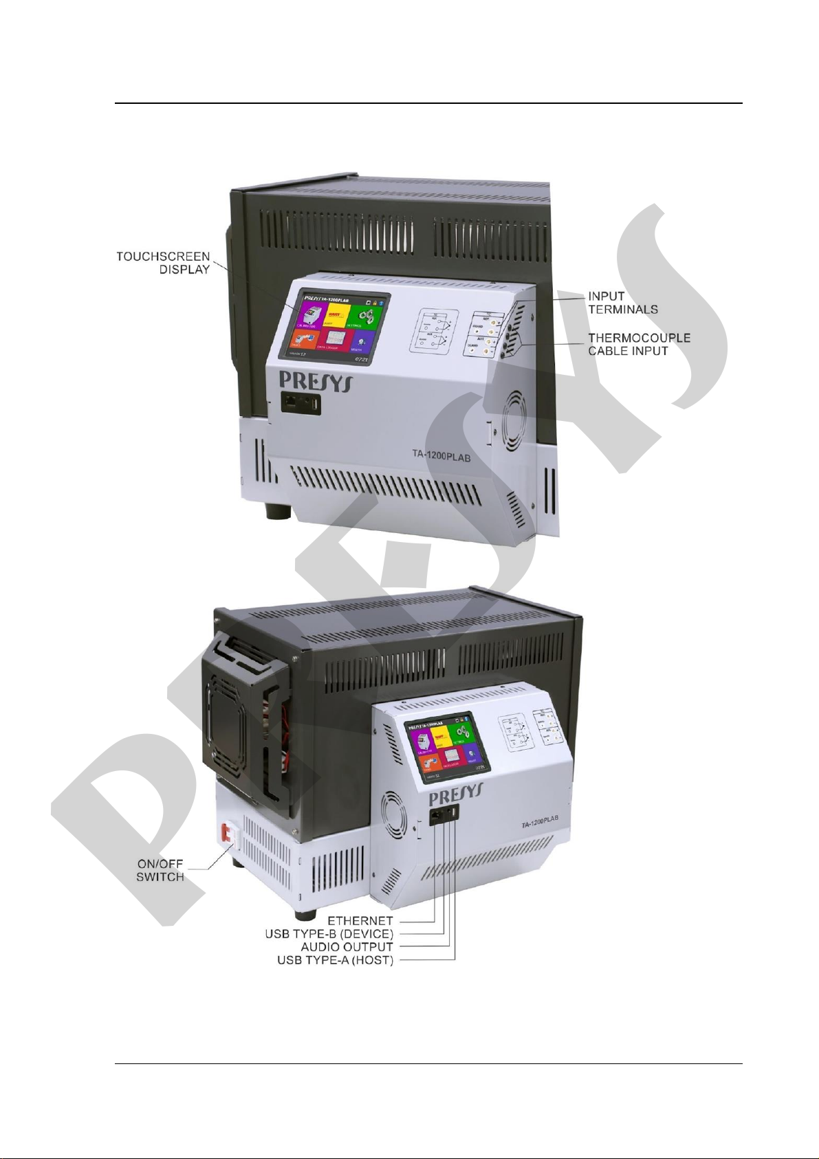
1.5 - Parts Identification
Fig. 03 - Parts Identification
presys
PRESYS Instruments TA-1200PLAB
Page 8
2 - Calibrator Operation
When powered on, the calibrator goes through a self-test routine and shows the
last adjustment date. In case of failure, it displays a message to indicate error; if that
occurs, the instrument should be sent to the manufacturer for repair.
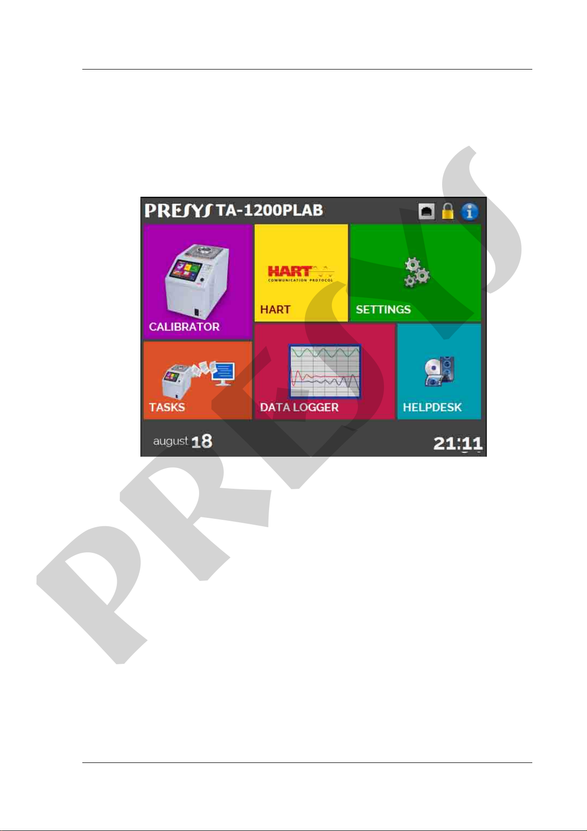
After the self-test is completed, the display shows the main menu:
Fig. 04 - Main Menu
The main menu is divided in four functions:
CALIBRATOR - selects the probe and input functions, see section 2.1
HART®- not available for this model.
TASKS -not available for this model.
DATA LOGGER - record measurements, enabling visualization in chart or table, see
section 2.2.
HELP DESK - features videos and documents to assist in the use of the calibrator, and
can also store files made by the user, see section 2.3.
SETTINGS - general instrument settings, see section 3.
presys
PRESYS │ Instruments TA-1200PLAB
Page 9
2.1 - Calibrator Menu
Toselecttheprobesetpointorelectricalinputfunctions,fromthemainmenu,press
the CALIBRATOR button. The following screen is displayed.
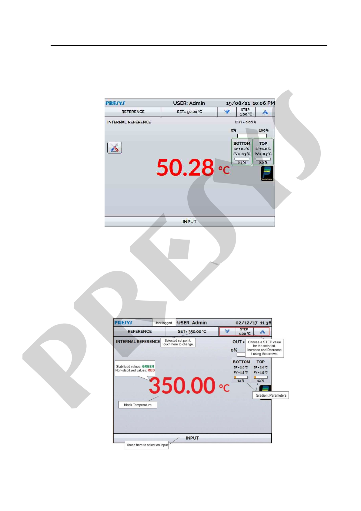
Fig. 05 - Calibrator Function
At the top is shown the probe settings and values.
The centered value shows the block temperature. The GREEN color indicates that
the temperature is stable, otherwise it is RED.
The set point value appears on the top. Touch in the SET bar or in the block
temperature value to change it. Pressing on the temperature unit it can be changed
between °C (Celsius), °F (Fahrenheit) or K (Kelvin).
Fig. 06 - Calibrator Mode
presys

PRESYS Instruments TA-1200PLAB
Page 10
In the STEP function, a step value can be configured, and the steps can be changed
through the up and down arrows.
In the Temperature Generation Configuration button , it is possible to
change the block setpoint rate in ° C / seconds.
In REFERENCE menu, you can configure the type of probe reference (see section
2.1.1 Probe Reference). The chosen reference appears just below the REFERENCE
button.
At the bottom, an input can be configured. When the input is selected, the screen
will split automatically. To select an input, just touch the INPUT bar (see section
2.1.2 INPUT MENU).
The icon shows a Quick Navigator, with the options for Main Menu (HOME),
Data-Logger and Tasks (not available for this model). Pressing MENU, there are options
for the selection of display Brightness and Memory Manager (see section 2.1.3).
Furthermore, it brings information about the auxiliary input configuration and IP address.
Press BACK to return to Calibrator Mode or HOME to go to the Main Menu.
Fig. 07 - Quick Navigator and Secondary Menu
2.1.1 - Probe Reference
There are two different references to the thermal block: Internal Reference and
External Reference.
The Internal Reference is a sensor built into the block.
The External Reference is an option for more accurate measurements. The
reference comes from a Standard Thermocouple Sensor placed inside the insert, among
the DUT (devices under test). This Standard Sensor should be a noble metal thermocouple
(R, S, B or Au-Pt types). To increase accuracy to the measurements, ITS-90 parameters
can be used to correctthe thermocouple electromotive force in reference to the IEC-60751
table.
presys

PRESYS │ Instruments TA-1200PLAB
Page 11
The configuration of the thermocouple calibration coefficients (C0, C1, C2 e C3
corrects the electromotive force (E) given by the linearization table of the thermocouple by
the IEC-60751 standard. After correction, the electromotive force of the thermocouple
follows this formula:
E’ = E + C0 + C1.t + C2.t² + C3.t³, where t is the temperature in °C and E’ and E the
electromotive force in mV.
When using External reference, the probe indication is displayed on the screen and
the control is made by the internal probe.
Fig. 08 - Choosing the Type of Temperature Reference
To select the Reference between Internal and External, touch the REFERENCE
bar. Select a reference between the registered sensors. To add a new sensor, select
MANAGER and ADD. When selecting External Reference, the ITS-90 parameters must
be set. If the sensor does not have parameters, use the value “zero” for all the coefficients.
ID: Sensor Identification
TYPE: Thermocouple type (R, S, B)
Scale: Reference table for the thermocouple
MIN and MAX: Operating range for the thermocouple
CJC: Type of Cold Junction Compensation. If MANUAL is chosen, inform the
temperature.
C0, C1, C2 and C3: Thermocouple coefficients.
presys

PRESYS Instruments TA-1200PLAB
Page 12
The coefficient values can be found in the Reference Sensor Certificate.
Fig. 09 - Adding a new Reference Sensor
After filling the blanks, click on SAVE button and confirm. The new sensor is now
available to be chosen in the list. To edit data from a sensor, select it and press MANAGER
button. To remove a sensor, select it and press REMOVE.
Fig. 10 - Connecting the Standard Sensor for the External Reference
Note: the values corresponding to controlled temperatures appear in GREEN / RED.
Values that show only the sensor indication appear in BLACK.
presys

PRESYS │ Instruments TA-1200PLAB
Page 13
2.1.2 - Input Settings
The INPUT menu has the following options:
Fig. 11 - Input Menu Options
For TC (thermocouple), you must select the thermocouple type and the type of cold
junction compensation (CJC): Internal or Manual. In Internal option, the compensation is
done internally; In Manual you must provide the value of the temperature of the cold
junction to the calibrator.
Fig. 12 - TC Menu Options
presys

PRESYS Instruments TA-1200PLAB
Page 14
2.1.2. - Input Connections Diagrams
Fig. 13 - Input Connections
2.1.3 - Saving Current Configuration (Memory Manager)
The TA Series calibrators admit several special functions that may become of
frequent use. In these situations, it is useful to store such settings in the instrumentin order
to save time.
After setting the desired calibration mode (input type or special function), press the
icon →MENU, and the button MEMORY MANAGER. On the option CREATE NEW
can be given a name for this configuration and a description. Press the SAVE button.
The operation that was being performed by the TA Calibrator shall be stored in
memory identified by the name given to it. To useit again, even after the calibratoris turned
off and on, select the name of the desired setting and press the LOAD button. The SAVE
AS DEFAULT button sets the current configuration as the default configuration of the
calibrator. Thus, every time the calibrator is turned on, this will be the initial configuration
of the calibrator.
2.2 - Data-Logger
The TA Series Calibrators allow you to record a series of measurements over time
to display data in chart or table format.
Select CALIBRATOR from the main menu and select the desired configuration for
Probe and Input.
Press the icon and select DATA LOGGER.
The calibrator automatically starts the measurements and displays each measured point
on the chart.
For measurements to be saved, you must press the REC button (see Figure 22).
With this option selected, all points (measurement and time) are saved in an internal file in
TA Calibrator, which can be used to generate a table or chart.
presys

PRESYS │ Instruments TA-1200PLAB
Page 15
Fig. 14 - Data Logger
In configuration menu (icon , you can edit the background color of the chart,
color and line thickness, sampling rate (in seconds) and set the x (time) and y
(measurements) axis of the chart.
Fig. 15 - Data-Logger Configuration Menu
Recording can also be programmed to start at a certain date and time in the
LOGGER option. Just set the start time and end time of recording. During the defined
range, the measured points are saved in an internal file in TA Calibrator.
To view a saved file press the OPEN button, select the desired file, and press
LOAD. The file name contains the date and time of the measurements.
The SHEET buttonallows the visualizationof data in table format, with the date and
time of the measurement and the measured values.
If the user wants to export the current data to a .csv file that can be opened in
spreadsheet softwares, press the SAVE button and indicate the name and where it will be
saved. The button saves the current screen image as a .png file. All saved screens can
be viewed in the IMAGE menu. These files are saved in the internal SD card of the
calibrator. To access the files saved on the TA Calibrator, connect the USB cable to the
computer (type A USB) and to the TA Calibrator (Type-B USB, see Figure 5).
presys

PRESYS Instruments TA-1200PLAB
Page 16
2.3 - Help Desk
The calibrator allows viewing of videos and documents. The videos can be viewed
while a calibration is performed and are intended to assist in the use of the calibrator. The
documents can be calibration procedures orinstructions that can be stored and viewed on
the calibrator itself.
From the main menu, when selecting HELP DESK and the VIDEOS tab, a list of
video categories will appear. Select the desired category and video. Press the FULL
SCREEN optiontoview the videoin full screen, orWINDOW for reduced screen.Selecting
the window option, it is possible to watch the video while using the calibrator functions.
To insert new videos in the calibrator, connect the USB cable to the computer (USB Type
A) and to the Calibrator (USB Type-B, see figure 05). Open the VIDEOS folder. Copy the
video to some subfolder (category) in the VIDEOS folder. If you prefer to create a new
category, just create a new folder within VIDEOS with the name of the desired category
and copy the file to this folder.
To insert documents, such as procedures or instructions, the files must be
converted into PDFfiles and mustbe saved inside the HELPfolderon the SD card;Create
a folder with the same name as the document and insert it into this folder.
3 - SETTINGS
The SETTINGS menu has 4 divisions (tabs at the bottom): DATE AND TIME,
NETWORK, SERVICES and SYSTEM.
3.1 - Date and Time
The date, time and time zone for the calibrator can be set in the date and time bar.
You can also set the decimal separator for .CSV files between commas and periods.
3.2 - Network
In the NETWORK tab it is possible to configure the IP address of the calibrator for
communication with the computer and the Wi-fi (wireless) network. The IP address can be
configured dynamically (DHCP) or it can have a fixed address (Disable the DHCP option
and change the desired addresses).
Communication via Wi-fi is carried out via USB/WIFI adapter (optional item). In the
NETWORK tab it is possible to configure the device name (name that calibrator will be
displayed on the network). By selecting CONFIGURE WIRELESS NETWORK (WIFI) the
user can view the available networks and configure which network he wants to connect to.
Connecting the calibrator to the network it is possible to view and print Reports /
Certificates of the tasks through the computer. Press the indicated network icon to access
the configured IPaddress after connected to the network.When connected to the wireless
network, the icon will be the Wi-fi network
fi network
presys
Table of contents
Other Presys Test Equipment manuals

Presys
Presys T-25N User manual

Presys
Presys MCS-12-IS User manual

Presys
Presys PCON-Y18-LP User manual

Presys
Presys PCA-570-RM User manual

Presys
Presys T-500PIR User manual

Presys
Presys PC-507-IS User manual

Presys
Presys MCS-XV User manual

Presys
Presys T-1200PIR User manual

Presys
Presys TA-1200P User manual

Presys
Presys T-350P User manual


