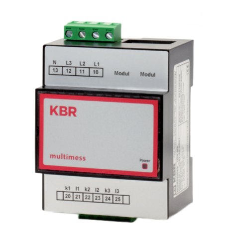
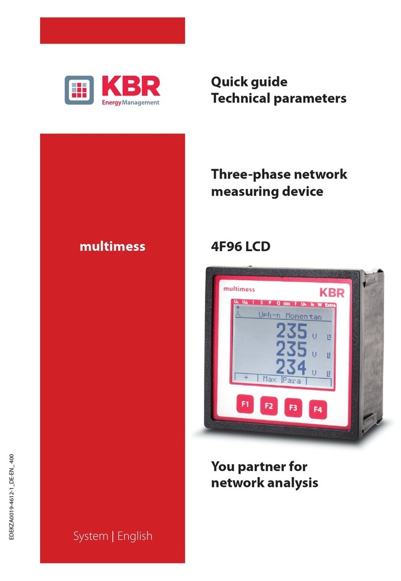
KBR multimess D6 User manual

EDEBDA0224-3823-1_EN
User manual
Technical parameters
Your partner for
network analysis
multimess D6
System IEnglish

© KBR Kompensationsanlagenbau GmbH
Misprints and printing errors
as well as technical changes reserved.
2
EDEBDA0224-3823-1_EN
Table of Contents
1 Introduction.......................................... 4
1.1 User manual .......................................... 4
1.2 Intended use......................................... 4
1.3 Explanation of
safety relevant symbols .................... 5
1.4 Safety notes........................................... 6
1.5 Product liability.................................... 7
1.6 Disposal .................................................. 7
2 Device memory.................................... 8
3 Denition of terms.............................. 9
4 Field of application/
range of functions.............................10
5 Connecting the multimess D6......12
5.1 Installation and assembly ..............12
5.2 Connection diagram........................13
5.3 Terminal assignment........................14
6 Start-up.................................................15
6.1 Control and display panel..............15
6.2 LEDs........................................................15
6.3 Default settings
after reset.............................................16
6.4 Basic device parameters.................17

V5.00 3
EDEBDA0224-3823-1_EN
KBR multimess D6
7 Measured values of the multimess
D6 and their representation..........18
7.1 Display of active or reactive
energy measurement ......................18
7.2 Display of power measurement...19
7.2.1 Display for energy consumption
or recovery...........................................19
7.2.2 Display of the power factor...........19
8 Programming......................................20
8.1 Working with the display menu...20
8.2 Programming scheme.....................25
8.3 Working with the
conguration menu .........................25
8.4 Storage..................................................35
8.4.1 Device settings...................................35
8.4.2 Long-term memory..........................35
8.4.2.1 Load prole memory .......................35
8.4.2.2 Annual energy memory..................36
8.4.2.3 Event memory
and operation logbook...................36
8.4.3 Measurement
period synchronization...................37
8.4.3.1 Synchronization only
by internal clock. ...............................37
8.4.3.2 Synchronization
by the KBR eBus.................................38
9 Serial interface ...................................38
9.1 Operating modes and
interface conguration ...................38
9.1.1 RS 485 Bus operation.......................38
9.1.2 Protective measures.........................38
10 Troubleshooting................................39
11 Technical data:....................................41
11.1 Measuring and display values ......41
11.2 Measuring accuracy .........................43
11.3 Measuring principle .........................43
11.4 Device memory..................................43
11.5 Power supply ......................................44
11.6 Operating and display elements.44
11.7 Hardware inputs................................44
11.8 Hardware outputs.............................45
11.9 Electrical connection .......................46
11.10 Mechanical data ................................47
11.11 Dimensioned drawing.....................47
11.12 Ambient conditions,
electrical safety and standards.....48
Fundstelle: Protokollbeschreibung
multimess D6 Modbus ...................................50

KBR multimess D6
V5.00
EDEBDA0224-3823-1_EN
4
Introduction
1 Introduction
Thank you for choosing this KBR quality product.
To familiarize yourself with device operation and conguration, we recommend
you read this manual carefully. This will enable you to make use of the entire
range of functions that this high-quality product oers.
The individual chapters serve to explain the technical details of the device and
show how to properly install and start up the device to prevent damage.
1.1 User manual
This user manual is included in the scope of delivery of the device and must be
accessible to the user at all times (e.g. in the switchgear cabinet). Even if the de-
vice is resold to third parties, the manual remains an inherent part of the device.
Although the utmost of care has been taken in putting together this user
manual, errors may still occur. We would be very grateful if you could notify us
of any errors or unclear descriptions you may notice.
1.2 Intended use
This device helps you to optimize energy consumption and avoid expensive
load peaks.
The system assists you in monitoring the energy consumption of your devices,
helps you to make optimum use of your tari and permanently lower your
energy costs.
This device does not, however, render careful system planning indispensable.
Moreover, it is essential that you take time to congure the device in line with
your system parameters on rst use and plan the shut-down of your devices.

V5.00
KBR multimess D6
EDEBDA0224-13823-1_EN
5
Introduction
1.3 Explanation of safety relevant symbols
These operating instructions contain notes that must be observed for your
personal safety and to avoid damage to equipment. These notes are identied
by a warning sign or information symbol, depending on the degree of hazard
they represent.
Warning
"Warning" means that death, major injuries or damage may occur if the appro-
priate safety measures are not taken.
Caution
"Caution" means that minor injuries or damage may occur if suitable safety
precautions are not taken.
Note
"Note" is an important piece of information on the product, its operation or the
respective part of the operating instructions to which special reference is being
made.
Disclaimer
The contents of these operating instructions have been carefully reviewed in
terms of the hardware and software described. Nonetheless, deviations cannot
be ruled out, and the manufacturer cannot guarantee 100% conformity. The
specications made in these operating instructions are reviewed on a regular
basis; any corrections required will be included in the next revision.

KBR multimess D6
V5.00
EDEBDA0224-3823-1_EN
6
Introduction
1.4 Safety notes
In order to prevent operating errors, device operation is kept as simple as possi-
ble. This will enable you to start your device up quickly.
In your own interest, however, the following safety notes should be read care-
fully. The applicable DIN / VDE regulations must be observed for installation!
Power supply connection, setup and operation of the device must be per-
formed by qualied personnel only. Qualied personnel as dened in the
safety notes in this user manual are those authorized to set up, ground and
mark devices, systems and circuits in accordance with applicable standards and
regulations.
To prevent re and electric shocks, the device must not be exposed to rain or
humidity!
Before connecting the device to the power supply, check whether the local
power supply conditions comply with the specications on the device name-
plate.
Caution
A faulty connection may result in the destruction of the device!
For device connection, the data given in the connection chart must be com-
plied with (see “Connection chart”) and there must be no voltage in the con-
nection lines. When wiring, always ensure that all wiring material used is neither
damaged nor defective and that the polarity is correct!
In order to ensure proper and safe product operation, it must be transported,
stored, installed and assembled in accordance with the specications, as well as
carefully operated and maintained.
A visibly damaged device must generally be considered unt for use and dis-
connected from the power supply!
Error detection, repair and maintenance work may only be carried out in our
facilities or after contacting our service team. Opening the device unauthorized
shall render your warranty null and void. Correct operation can no longer be
guaranteed!
Opening the device may expose live parts. Capacitors in the device may still be
under load, even if the device has been disconnected from all voltage sources.
Open devices must not be operated!

V5.00
KBR multimess D6
EDEBDA0224-13823-1_EN
7
Introduction
Systems that are at risk from lightning strikes must feature lightning protection
for all input and output lines.
1.5 Product liability
You have purchased a high-quality product. Only components of the highest
quality and maximum reliability are used.
Each device is subject to long-term testing before it is delivered.
For details on product liability, please refer to our general terms and conditions
for electronic equipment, which you can nd at www.kbr.de.
The warranty on device properties applies only if the device has been operated
in accordance with its intended use!
1.6 Disposal
Defective, outdated or disused devices must be properly disposed of.
If required, we are happy to dispose of the devices for you.

KBR multimess D6
V5.00
EDEBDA0224-3823-1_EN
8
Device memory
2 Device memory
Non-volatile long-term memory
The device is equipped with an internal, non-volatile memory in which long-
term data is stored.
Buered real-time clock (RTC)
After an uninterrupted charging time (device connected to the supply voltage)
of approx. 8 hours, the buer capacitor will have a sucient charge to protect
the internal clock from failure due to lack of operating voltage for approx. 14
days.
Note
If the buer capacitor is discharged and there is no supply voltage, once the
device has been switched on the time settings will be incorrect and must there-
fore be reset.

V5.00
KBR multimess D6
EDEBDA0224-13823-1_EN
9
Denition of terms
3 Denition of terms
Below, you will nd brief explanations of the terminology used in this manual.
Root-mean-square value:
By denition the square of the average value of a periodic or pulsating value is
referred to as the root-mean-square value. multimess D6 exclusively uses the
RMS values of pure periodic values.
Instantaneous root-mean-square value:
The value determined by the multimess D6 during its measurement intervals.
Measurement interval:
During a measurement interval, the electrical quantity “Voltage”or “Current”
of one phase is scanned. The resulting scanning spots are available for further
calculations. This interval is mainly determined by the A/D conversion.
Measuring cycle:
The measuring cycle is the time the measuring device needs in order to mea-
sure all the values recorded by the device for all three phases.
Firmware:
The operating system software implemented in the multimess D6’s microcon-
troller.
Load prole memory:
Saves the actual values of the measurment periods with timestamp.
Measurement period maximum value:
The measurement period containing the highest (maximum) value that oc-
curred.
Active/reactive power periods:
Actual active or reactive power within a measurement period.
Measurement period:
The period of time used to determine the average power demand. Typical inter-
vals: e.g. 15, 30, 60 minutes.
DIN rail
Top hat rail / mounting rail acc. to DIN EN 50022

KBR multimess D6
V5.00
EDEBDA0224-3823-1_EN
10
Application/range of functions
4 Field of application/range of functions
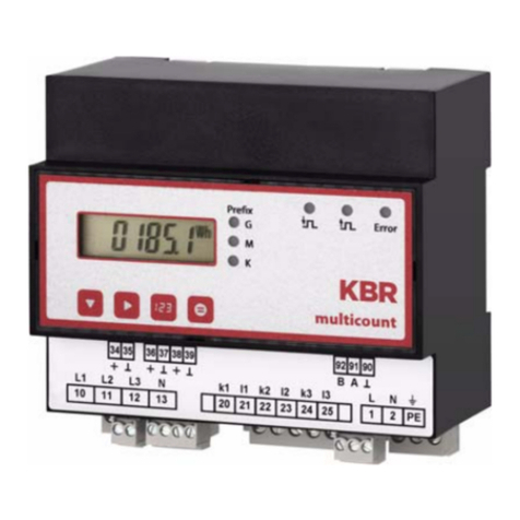
multimess D6 is a compact, easy-to-use energy meter that records active as well
as reactive energy (for consumption and recovery).
This energy counting device was designed in accordance with the standards
DIN EN 61036 (IEC 1036), DIN EN 61268 (IEC 1268) and requirement specica-
tion 2.0 revision 12/97 by the German Electricity Association (VDEW).
Dual-tari counter function (HT/LT)
Consumption during high tari and low tari times is saved separately. Switch-
ing from high to low tari times and vice versa is either carried out by means of
a digital signal to be applied externally, e.g. from the energy supplier, or via an
internal clock. A display ashing on the front of the device indicates which tari
is active at the moment. When operated with the KBR Energy Bus, switching can
also be carried out centrally via the Multimaster or computer.
Convenient operation and display
The LCD serves to either display the measured values directly or enter the re-
spective parameters and conguration data. In addition, six LEDs serve to show
the status and monitor the functions. Four buttons facilitate clearly structured
navigation through the menus.
For 100 to 400 V networks
The multimess D6 can be applied in three-wire as well as four-wire networks.
If the measuring value displays in the three-wire network are incorrect, a ze-
ro-point creator should be used. The unit can be implemented in 100 V as well
as in 400 V networks for direct measurement. Using a transducer adaptor, up to
700 V can be connected to the meter. Higher voltages can only be connected
via external voltage transformers, whereby primary and secondary voltage can
be freely programmed. The measuring voltage inputs of the device measure
directly, i.e. they are not metallically separated by a voltage transformer!
For energy supply networks with outer conductor connected to the earth po-
tential, suitable control gear with electrical isolation (e.g. voltage transformer)
must be used.
x/5A or x/1A freely programmable
The measuring inputs for current must always be fed via current transformers,
while the transformer ratio is programmable. The primary current value as well
as the secondary current value can be selected.
Programmable pulse output
Active energy or reactive energy proportional pulses can be output via a
programmable output laid out as an S0interface. The pulse output type (in
proportion to active or reactive energy
V5.00
KBR multimess D6
EDEBDA0224-13823-1_EN
11
Application/range of functions
for consumption or recovery) as well as the pulse values (number of pulses per
kWh or per kvarh) and the pulse length can be congured. These pulses can be
processed by, for example, a master system for data acquisition or optimization,
a maximum-demand monitor or a central process control.
Each pulse is visualized by a ashing LED.
Serial interface for connection to the KBR Energy Bus
In its default conguration, the multimess D6 has a serial interface
(RS-485) for operation with the KBR eBus.
A large amount of information that cannot be shown on the display can be read
from the device via the Energy Bus.
Thus the online measuring values of the individual power factors and the indi-
vidual power as well as a large amount of data can be read from the long-term
memory.
Extensive storage functions
In addition to its counting functions, the multimess D6 oers extensive memo-
ry functions:
4-quadrant load prole memory to record the cumulated active and reactive
power
Memory to record the daily energy values for 365 days
Memory for the previous month’s maximum measurement period
Event memory (4096 entries), for logging actions of the meter such as mains
failures, tari switches, delete functions etc.
These memory functions are only available via the KBR eBus.
Synchronization
Synchronization as well as high/low tari switching can be controlled centrally
via the KBR eBus or via the internal clock.
Software (optional)
A number of software products that can be run on most Microsoft® Windows®
operating systems is available for the convenient programming and storage of
long-term data.
Separate power supply
The device requires a separate auxiliary voltage for operation (see nameplate).
For questions on this device or on our software products please don’t hesitate
to contact us. We will be glad to assist you. Please see the cover sheet of this
manual for your contact address.

KBR multimess D6
V5.00
EDEBDA0224-3823-1_EN
12
5 Connecting the multimess D6
5.1 Installation and assembly
The housing of the multimess D6 has been designed for wall mounting on a
35 mm DIN rail. The module is assembled to the mounted DIN rail.
Caution
The control voltage as well as the applied measuring voltage of the device
must be protected by means of a back-up fuse. When connecting the current
transformers, the energy ow direction and the correct assignment to the
voltage paths must be observed!
For the wiring of the pulse output, we recommend to exclusively use shielded
twisted pair material to avoid disturbance (e.g. installation line I-Y(ST) Y 2x2x-
0.8mm, whereas the shielding may only be connected on one side).
During installation, please also observe our notes on safety measures against
overvoltage and lightning in the chapter“Protective measures” of this manual.
Note
You should take the following points into consideration when connecting
the device to the three-phase network
to be measured:
- Energy ow direction
- Assigning of measuring voltage input/current transformer input
Rotary eld:
As soon as the multimess D6 is connected to the mains, it will automatically
detect the rotary direction.
Current transformer connection:
Energy ow direction:
When mounting the transformers, observe the current ow or energy ow
direction. If the current transformers are inserted the wrong way round, the cur-
rent will have a negative sign for active power input. In this case, interchange
the pins of the terminals k and l of the aected transformers.
Connecting the multimess D6

V5.00
KBR multimess D6
EDEBDA0224-13823-1_EN
13
5.2 Connection diagram
Stromussrichtung / current direction
Impuls
Ausgang
Impuls
output
Eingänge
Inputs
Messspannung
Measuring voltage
Messstrom
Measuring current
Netz
Power
Tarif/Tari
Schnittstelle
Interface
Modbus
Connecting the multimess D6
Assigning measuring voltage input / current transformer input:
The current transformer on terminal 20/21 (k1/l1) must be arranged in the
phase where the measuring voltage for terminal 10 (L1) is measured. The same
applies to the other transformer and measuring voltage connections.
Caution
Before any interchanging, the current transformers must be shorted out.

KBR multimess D6
V5.00
EDEBDA0224-3823-1_EN
14
Connecting the multimess D6
5.3 Terminal assignment
Terminals 1 (L) / 2 (N) and PE Power supply connection
A control voltage is required to supply the
device with power. The device can be op-
erated with a voltage from 85 V to 265 V.
Terminals 20 (k1) and 21 (l1)
22 (k2) and 23 (l2)
24 (k3) and 25 (l3)
Current measuring inputs
The measuring inputs for current must be
connected via current transformers x/1A
AC or x/5A AC.
When connecting transformers, pay atten-
tion to the energy ow direction and the
correct assignment of measuring voltage
inputs to the current transformers.
Terminals 10 (L1)
11 (L2)
12 (L3)
13 (N)
Voltage measuring inputs
Three phase voltage measurement in
4-wire alternating current networks.
Direct measurement is possible in the
following networks: 3 x 100V/57,7V AC;3 x
400V/230V AC;
For higher voltages, the unit needs to be
connected via a voltage transformer.
Terminals 92 (B)
91 (A)
90 (earth)
Bus connection
For device conguration and for
communication at the KBR eBus
Terminals 34 (+) and 35 (-) Pulse output
Output of energy-proportional
pulses via a digital contact (S0interface in
accordance with DIN 43864). Paying at-
tention to the correct polarity is important
for this output. The output signals can be
processed by a maximum demand moni-
tor or a master central process control, for
example.
Terminals 36 (+) and 37 (-) not in use
Terminals 38 (+) and 39 (-) Tari input
A oating contact, e.g. from the energy
supplier for switching from high to low
tari, can be connected to this input.

V5.00
KBR multimess D6
EDEBDA0224-13823-1_EN
15
Commissioning
6 Start-up
6.1 Control and display panel
The multimess D6 features four key buttons, , , and , to reach
the individual menus and submenus for programming the device. The 6-digit
LCD serves to display the currently selected measured values. Six green LEDs
indicate the signicance of the measured data as well as dierent messages.
6.2 LEDs
LED “K” While the LCD shows the type of measurement and the measured
LED “M” numerical value, the three prex LEDs “K,”“M” and “G” show the
LED “G” signicance of the unscaled unit. It is decisive which LED is active:
- “K” means that the value is shown in “kilo…” (e.g. [kW]),
- “M” stands for“mega…” (e.g. [MVAr]) and
- “G” corresponds to “giga…” (e.g. [GVA]);
- if no LED is active, the value is represented as an unscaled unit.
LED “Error” This LED ashes if an error message is waiting or an error has
occurred.
LED Not in use
LED This LED always ashes when the pulse output is active.

KBR multimess D6
V5.00
EDEBDA0224-3823-1_EN
16
Commissioning
6.3 Default settings after reset
Measuring voltage, primary 400 V
Measuring voltage, secondary 400 V
Measuring current primary 5 A
Measuring current secondary 5 A
Zero-point creator Deactivated
Daylight saving time from months 03 to 10
Frequency correction automatic
Current average value over 10 minutes
Tari switching Bus
Default setting for
internal tari switching
Start time: 00:00 for LT start,
End time: 00:00 for LT end
All measurements Restart
Energy Memory Deleting all energy memories
Measurement period 15 min.
Measurement period memory Deleting all entries
Synchronization type internal
Attenuation coecient for current/
voltage
0
Pulse output type proportional to active energy, active energy
consumption
Pulse value 1 pulse / kWh
Pulse length at pulse output 100 ms (Te/Ta =50/50)
Tari HT
Password Default setting 9999,
device can be freely congured
Unaected by a RESET: Bus address and time
Basic conguration when
delivered: All settings set to default values.
Bus address is 0000.

V5.00
KBR multimess D6
EDEBDA0224-13823-1_EN
17
Commissioning
6.4 Basic device parameters
Parameters Stored by user
Measuring voltage, primary programmable by user from
1 to 99.99kV
Measuring voltage, secondary programmable by user from
1 to 600V
Measuring current; transformer pri-
mary current
programmable by user from
0001A to 9999 A
Measuring current (at device input,
i.e. secondary transformer!)
can be selected by user:
1A or 5A
Pulse output type / pulse value according to user settings -
0.00 to 9999 P/kWh
Pulse length 30 to 990 ms
Tari switching user can select digital input, switching via
KBR eBus or at times programmed in the device
Synchronization settings Setting options: Bus and internal clock
Bus mode Choice of KBR eBus, Modbus RTU or Modbus
ASCII
Bus address according to user settings between 0001 and
9999 for KBR eBus and 1 to 247 for Modbus
Time acc. to user settings in hh:mm:ss
Password according to user settings, password is a 4-digit
number (leading zeros); 9999 means: Device is
not password-protected
Device name any name chosen by the user 1*)
Event name an individual designation is assigned to
every event
Measurement period 1 / 15 / 30 / 60 min. 1*)
1*) This function can only be set using the computer, with optionally available software
(e.g. visualenergy).

KBR multimess D6
V5.00
EDEBDA0224-3823-1_EN
18
Measured values
7 Measured values of the multimess D6
and their representation
The following section provides an overview of the measured values of the
multimess D6 and their representation on the device. The respective measuring
range is automatically switched over in the display.
T1 12 Wh G
M
k
T1 345 Wh G
M
k
T1 678.9 Wh G
M
k
Example:
Display:
7.1 Display of active or reactive energy measurement
T1 000000 Wh
T2 Varh
Display:
High tari HT
Display:
Low tari LT
Display:
Consumption or
recovery
5 places for
display of measured
values
Display:
Active energy [Wh]
Display:
Reactive energy [Varh]

V5.00
KBR multimess D6
EDEBDA0224-13823-1_EN
19
Display of the active energy WAct in kWh, MWh or GWh and the reactive energy
WReact in kVArh, MVArh or GVArh. The output measuring value must be calculat-
ed with the respective display signicance“Kilo,”“Mega”or “Giga,” depending on
the active LED.
7.2 Display of power measurement
The total active power measurement is identied by a„p“ in the rst place,„s“
identies the total apparent power measurement and„q“ identies the total
reactive power measurement.
Active power during energy consumption is displayed without a polarity sign,
during energy recovery with a negative polarity sign. For inductive reactive
power, the measured value is preceded by an„i“; capacitive reactive power is
identied by a„c“.
For the display of the measured values themselves the same principles apply as
for the display of active and reactive energy. The output measuring value must
be multiplied with the respective display signicance„Kilo“,„Mega“or„Giga“,
depending on the active LED.
Display of active power in W, kW, MW, GW, the apparent power S in VA, kVA,
MVA, GVA and the reactive power Q in Var, kvar, Mvar, Gvar.
7.2.1 Display for energy consumption or recovery
Whether energy is recovered can be determined by means of the polarity sign
for the active power and the continuous counter.
7.2.2 Display of the power factor
If the power factor λ is measured, this is indicated by “PF” (power factor) in the
rst of the two spaces in the display.
By denition the power factor is the relationship of the active power to appar-
ent power
ΙPΙ
λp = PF=
S
In contrast to the cos φ, for the power factor λ the proportion of distortion
reactive power is included in the calculation.
Display of the power factor λ in the range 0.00 to 1.00.
Measured values

KBR multimess D6
V5.00
EDEBDA0224-3823-1_EN
20
Programming
8 Programming
The multimess D6 is programmed using the 4 keys , , and .
8.1 Working with the display menu
Pressing the navigation key jumps to the respective
following menu item.
Note
The active tari is indicated by permanent ashing of the respective tari dis-
play T1 or T2 in every display menu.
Active energy for
low tari
Display of the accumulated active
energy in low tari.
The tari display T2 (low tari)
lights up permanently.
The tari display T1 ashes, i.e. the
current counting tari is T1 (high
tari)
T1 2.35 Wh
T2
Menu LCD Unscaled unit
Active energy WAct
for high tari T1 2345.6 Wh kWh if the prex LED "k" lights up. (if
the prex LED “G” or “M” lights up,
other menus are available)
Continue in the main menu
or
For meter count detailed view
T1 2Wh Detailed view gigawatt-hours
GWh if the prex LED “G” is active
Continue with or to
jump back to the basic menu
T1 456 Wh Detailed view megawatt-hours MWh
if the prex LED “M” is active
Table of contents
Other KBR Measuring Instrument manuals

KBR
KBR multicount D5-0-LCD-1DO-3P-75A-MID User manual

KBR
KBR D9-PQ User manual

KBR
KBR multimess 4F96 LCD User manual

KBR
KBR multilog 3 User manual

KBR
KBR multimess F144-2-LED-ESMS 4 Series User manual

KBR
KBR multisio 5D6-ESBS-5DI6RO1DO User manual

KBR
KBR multimess F144-0-LED 5 Series User manual

KBR
KBR multimess F144-0-LED-EP 4 Series User manual

KBR
KBR multimess 1D4 User manual

KBR
KBR multisys 1D3-ESDP Operating instructions