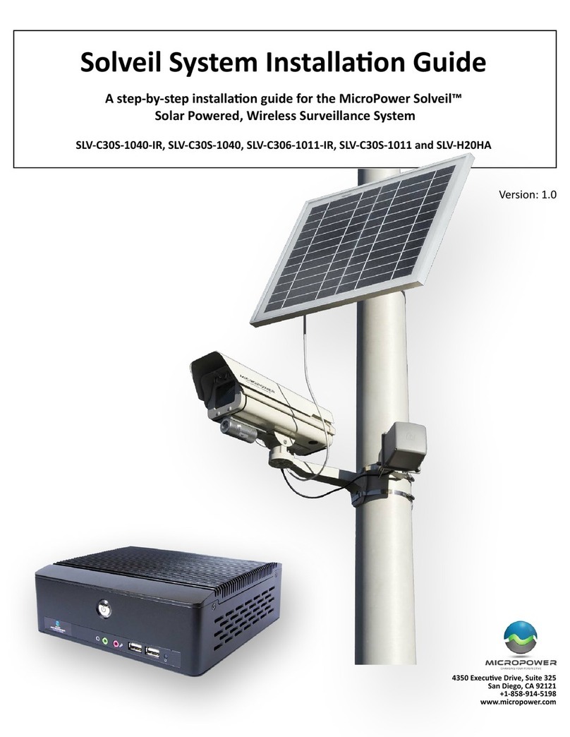
MICRO-POWER Helios User manual

© 2012 MicroPower Technologies, Inc. 1
4350 Executive Drive, te. 325
an Diego, CA 92121
+1-888-854-3312
www.micropowerapp.com
Helios™
olar Wireless IP urveillance ystem
Installation Guide
Version 5.0

Helios Installation Guide
© 2012 MicroPower Technologies, Inc. 2
Table of Contents
Contacting MicroPower Customer Support 3
General Safety Precautions 3
Package Contents 4
System Overview 5
Installation Recommendations 6
I.
Site Survey 6
II.
System Setup 7
III.
Mounting the MiniHub and Rugged-i camera 24
IV.
Adjusting the Camera Image 28
V.
Configure the Video Management Software (VMS) 29

Helios Installation Guide
© 2012 MicroPower Technologies, Inc. 3
Contacting MicroPower Customer Support
MicroPower’s customer support strategy is through best-in-class business partners
including OEMs, distributors, systems integrators and systems vendors If your
MicroPower product was purchased directly from a MicroPower business partner, that
partner is the first point of contact for technical support If the business partner cannot
resolve a problem, then the partner will contact MicroPower
Web Support: http://www micropowerapp com
Email Support:
help@micropowerapp com
Phone Support Worldwide:
+1
-
888
-
854
-
3312
Fax Support – Worldwide: +1-858-947-3907
General Safety Precautions
• Follow all cautions, instructions, and warnings as listed on the product and related
documentation, including electro-static discharge (ESD) recommendations, physical
handling advice and other recommendations or best practices
• Use ESD precautions when unpacking and installing MicroPower camera and hub
products ESD mats and grounding straps are recommended
• Ensure that the voltage and frequency of your power source match the voltage and
frequency required by the equipment Do not use an alternative power supply
• Ensure that the battery size and voltage match the size and voltage required by the
equipment Failure to do so could result in damage to the equipment and nullification
of the product warranty
• Use only the included antennas and ancillary equipment provided with the product
• Do not make mechanical or electrical modifications to equipment MicroPower is not
responsible for the safety or regulatory compliance of a modified product
• Do not omit device components that would interfere with air flow and cooling as
designed Failure to follow these guidelines can cause overheating and affect the
reliability of your MicroPower product
• Protect your warranty A product which has been damaged, misused, abused or
misapplied may be determined to be out of warranty

Helios Installation Guide
© 2012 MicroPower Technologies, Inc. 4
Package Contents
Helios Solar Wireless IP Surveillance System consists of two major devices; the MPT
2500 Rugged-I Solar Wireless IP Video Camera and the MPT 2700 Wireless Video Hub
MPT 2500 Rugged-i™ olar Wireless IP Video Camera
•One Directional Antenna (Combination for Narrowband and Wideband)
•Rugged-i Camera
•Camera Mounting Arm
•Mounting Hardware (IP66 Enclosure) for Camera
o3 Hex 10 mm Philips head screws
o2 attachment Philips screws
o3 plastic sleeves
•Antenna Mounting Bracket
oU-Bracket
o2 attachment screws and nuts
MPT2700 MiniHub™ Wireless Video Hub ystem
•One Directional Antenna
•Antenna Mounting Bracket
oU-Bracket
o2 attachment screws and nuts
•MiniHub
•Power Cord

Helios Installation Guide
© 2012 MicroPower Technologies, Inc. 5
System Overview
MicroPower Technologies has developed a unique power and wireless technology,
TrustLinx, that is 90% lower power and 400% longer range than traditional wireless IP
video camera technology With this proprietary and patented technology, the
MicroPower outdoor IP video cameras can be operational for five days without being
recharged by the sun and maintain 24 hour operation at 5 frames per second (fps) In
addition, TrustLinx, has a unique capability to cooperate with multiple wireless
technologies that allow the transmission of video data at a potential distance of 1/2 mile
with the highest possible video quality
Because of this unique and proprietary technology, the MicroPower Technologies Helios
System with the MPT2500 Rugged-i Solar Wireless IP Video Camera and the MPT2700
MiniHub Wireless Video Hub work in tandem to provide a wireless IP video system
which allows for the placement of the outdoor wireless IP video camera system
practically anywhere that is needed Thus, the MicroPower system eliminates the need
for digging trenches to connect power to outdoor IP video cameras, significantly
reducing installation time and labor costs
Up to six (6) Rugged-i IP video cameras can be associated to each MiniHub The
MiniHub is the data connection to a broadband Internet access point The broadband
Internet access point can be a wireless or wired router, or a broadband modem (cable
model or ADSL modem)

Helios Installation Guide
© 2012 MicroPower Technologies, Inc. 6
Installation Recommendations
There are 5 major steps that are recommended for a successful installation These are:
1 Site survey
2 System setup
3 Mounting MiniHub and Rugged-i camera
4 Adjust focus of the camera
5 Configure VMS
I. Site Survey
A well-thought out plan for the location of the hub and camera(s) are important steps to
ensuring that the entire system can communicate and integrate with a new or existing
video surveillance and management system For complete guidance on performing a
quality site survey, please refer to the MicroPower collateral titled “Site Survey
Guidelines”
For best results, a line-of-sight design between the Helios system can provide a range of
up to 1/2 mile However, obstacles such as buildings, concrete, steel or stucco walls
and ceilings will impact the wireless performance in terms of reach and data rate
speeds Hence, these items can affect performance and range so that the distance
between the MiniHub and Rugged-i camera may need to be reduced If the distance
between the MiniHub and a Rugged-i camera is too far, then the video will either be
non-operational since the MiniHub and Rugged-i camera did not pair correctly, or there
will be noticeably slower frame rates The distance between the MiniHub and a
Rugged-i camera must be a minimum of 25 feet For further education and guidelines
on RF effects, refer to MicroPower document “A Guide to Optimizing Your RF Setup”
Since the Rugged-i camera is powered by solar, the impact of shadows and sun direction
is an important consideration The Rugged-i does not require direct alignment with the
sun, but it is advisable to place the camera in a location which receives an adequate
amount of sunlight throughout the day The best time to perform a sun profile for all
cameras is during the peak hours of sunlight from 11 a m to 3 p m to determine shadow
avoidance strategies
If the Rugged-i camera is being installed in the Northern Hemisphere, ideally the panels
and cameras should be placed on the OUTH side of a pole or facing OUTH to minimize

Helios Installation Guide
© 2012 MicroPower Technologies, Inc. 7
shadows created by the attached pole East and west facing cameras are acceptable but
not optimal Avoid placing the camera on the NORTH end of a pole or facing NORTH If
the Rugged-i camera is installed in the Southern Hemisphere, ideally the panels and
cameras should be placed on the North side of a pole or facing NORTH for minimal
shadow impact
For more information, see the following link
http://www ehow com/how_6069191_install-panel-direction-aiming-degrees html
In addition, areas that are not recommended include:
•Indoors
•Under a roof eave
•Underneath a tree canopy or foliage which does not receive adequate sunlight
•Next to a building that will create shadows at a different part of the day
Additionally, please make sure there are minimal obstructions to the camera antennas
and that they are able to be appropriately positioned to receive and transmit data and
video to the hub
II. System Setup
The following steps are required when performing system setup and installations
1 Add antennae to MiniHub
2 Configure MiniHub for the final IP address desired
3 Reboot the hub system
4 Add camera through the web interface
5 Add camera antennae
6 Connect the battery cables to the camera
7 Adjust camera settings if necessary
8 Verify the pairing between the MiniHub and Rugged-I camera in a close
proximity environment
9 View the camera connection through the web interface and Live Connection
10 Begin mounting process of the final locations for the MiniHub and cameras

Helios Installation Guide
© 2012 MicroPower Technologies, Inc. 8
For most systems, the pairing between the MiniHub and the Rugged-I Camera have not
been performed If the pairing between the MiniHub and Rugged-I camera has been
performed by the factory (steps 1 – 5 have been completed), the user only need to
perform the VMS setup Refer to the documents titled VMS setup for your specific
VMS
During the configuration and pairing exercise, the antennas for the MiniHub and
Rugged-i Camera are required to be attached before the battery connection with the
camera is connected
A. Accessing the MiniHub
Accessing the MiniHub is similar to setting up a wireless router in the home A display
or network console is used to directly address the MiniHub There are two basic
topologies in which the MiniHub can be addressed The common method for systems
which already have a sophisticated network in place is addressing the MiniHub through
a network switch It is also possible to communicate to the MiniHub from a server
directly to the MiniHub through a crossover cable Below are illustrations of both
topologies
Network Switch Topology
Crossover Cable Topology

Helios Installation Guide
© 2012 MicroPower Technologies, Inc. 9
B. System Setup via the MiniHub
It is important to configure the MiniHub first, prior to pairing the MiniHub to the
Rugged-i cameras System setup is performed through a web Interface while addressing
the MiniHub through a network console, similar to how a wireless router is configured in
a home setting
The MiniHub must be connected to a network switch prior to configuring the MiniHub
or directly to a laptop/network server through a crossover cable Communication to
the administration console application of the MiniHub is performed through a standard
browser via a network console (Note: The MiniHub is a fully operational Linux server
Any application that is loaded on to the MiniHub will nullify the MicroPower
Technologies warranty )
To configure the MiniHub, you will need to:
1
Connect the AC power cable to the MiniHub and plug into a power source
2
Connect MiniHub Antennae
3
Power on the MiniHub using the toggle button on the rear of the unit Make sure the
Rugged-i camera and MiniHub are at least 25 feet away from each other
4
Configure the network console so that it can directly address the MiniHub The default
IP address of the MiniHub is 192 168 0 100 You may need to modify the IPv4 adapter
settings of the network console to match the default MiniHub IP address, since it is
required to be in the same domain to be addressable To communicate to the MiniHub,
the first three numbers of the IP address of the network console need to match that of
the default MiniHub IP address In this case, it is necessary to enter 192 168 0 XXX
where XXX is any number not previously issued within connected network
Power Toggle
Button
Antenna Connector(s)
AC
Power

Helios Installation Guide
© 2012 MicroPower Technologies, Inc. 10
Below is an example screen of modifying the IPv4 properties in Windows to make this
change
.
Press OK
5
To communicate to the MiniHub through the network console, type the default IP
address of the MiniHub in a browser
http://192 168 0 100
This is a temporary IP address which will eventually be modified through the system
setup application
At this point, a login screen will appear This is the MicroPower Technologies setup
application This login screen will look like the following
:

Helios Installation Guide
© 2012 MicroPower Technologies, Inc. 11
Type in admin for the username The password should be left blank
At this point, the System Setup Web Interface will appear Six tabs will be available; System
Setup, Add/Remove Camera, Camera Settings, Hub Interface, Camera Info and Hub Status All
instructions and menu options to this Installation Guide pertain to Version 16 16 or greater
You will note Version 16 16 by looking up the Version number in the Hub Status Tab
The firmware version is located in the Web Interface on tab, Hub tatus, under the heading
PKTVER See below

Helios Installation Guide
© 2012 MicroPower Technologies, Inc. 12
6
Begin configuration of the MiniHub by selecting the System Setup tab
This is the menu used to specify the final IP address, hostname, WiFi channel, Wi-Fi
bandwidth, narrow band channel number, narrow band channel power and time out period
Typically, you will only need to change the IP address To configure the IP address, single
click the IP address The user will then be directed to a Configure Hub IP address menu
See below
This menu allows a user to modify a static IP address, gateway address, subnet address or
choose Dynamic otherwise known as DHCP (Dynamic Host Configuration Protocol)
Note: Caution should be used in using DHCP, since the IP address will be dynamic, making it
difficult to determine the appropriate IP address to access the setup menu in the MiniHub
The only access to the MiniHub for setting modifications is by using the IP address as the
URL in the web browser Hence, using DHCP would require assistance from the IT
administrator to perform discovery to determine the assigned IP address of the MiniHub at
the moment in which modifications are desired
The new Hub IP address should correspond to the IP address within the subnet of your
network For instance, should your devices be assigned an IP address of 192 168 100 1,
192 168 100 5 and 192 168 100 10, then a viable Hub IP address would be 192 168 100 150

Helios Installation Guide
© 2012 MicroPower Technologies, Inc. 13
This allows other devices within your subnet network, including the NVR, to communicate
with each other Input the desired IP address and select Update
After updating the “Configure Hub IP Address menu”, you will be directed to the previous
menu, System Setup
When Apply is selected at the System Setup tab, a dialog box will be displayed informing the
user that a system reboot is required, since the MiniHub will not be configured for the new
IP address until a reboot is complete A manual reboot is performed by toggling the power
button in the back
The other variables (WiFi Channel, Demod Level, Narrow Band Chan, Narrow Band Pwr) are
selectable, but should not be necessary to change
7
Address the hub through the network console and type in the new modified IP address
http://xxx xxx xx xx
The administration login screen will reappear If there is a problem, then the IP address
may need to be readjusted on the IPv4 properties page so that the network adapter is
within the same domain as the new MiniHub IP Address

Helios Installation Guide
© 2012 MicroPower Technologies, Inc. 14
C. Add/Remove Cameras
This is the menu used to add or remove cameras that are associated with the specific
hub that is being configured
1
Connect the antennas to the camera
2
Select Tab labeled Add/Remove Camera
3
Select option to “Add New” A pop-up window for the MAC address of the camera is
displayed
Add the MAC Address that is printed on the sticker of the Rugged-i camera The sticker is
located inside the camera enclosure You will need to open the safety latch on the camera
in order to access the inside of the Rugged-i camera
Press OK when the MAC address is entered
1
Follow Step 3 again to add additional cameras (maximum of 6)

Helios Installation Guide
© 2012 MicroPower Technologies, Inc. 15
2
Inside the camera enclosure, connect the battery charger cable to the battery
connector The camera ships with a fully charged battery pack However, when the
Rugged-i camera is shipped from the factory, the battery charger is disconnected from
the battery connection While the camera enclosure is open, it is best to attach the
battery charger connectors together You should hear a beep that indicates power
being supplied to the system, when you complete the connection
The LED indicator light (on the left side while peering inside the camera) should glow red
when the battery is connected
3
Close the camera housing then lock the safety latch

Helios Installation Guide
© 2012 MicroPower Technologies, Inc. 16
D. Camera Settings
The tab, Camera Settings, is used to customize each Rugged-i camera associated with
the paired MiniHub
1 Select tab labeled Camera Settings.
Vvariables for the Camera Settings beyond the MAC address are:
Variable Description Valid value for
Rugged-i cameras
MAC
Camera MAC Address
Six Hex values
WB Power
Power settings for the Wideband signal
Hi, Med, Lo
Demod Data bandwidth of the individual
cameras
54, 48, 36, 24 Mbps
Fr Rate
Frame rate desired
5
Invert State Specifies whether the video is an
inverted image or not
Off
Encrypt State
Determines whether data uses
encryption between the Rugged-i and
MiniHub This is a future feature
Off
Stream Displays the stream ID of the camera StreamX where X can
be 0 to 5
Use the Apply button at the end to apply new settings for that specific camera
The Align button is used for aligning antennas See below for further information

Helios Installation Guide
© 2012 MicroPower Technologies, Inc. 17
E. Align Mode
The very last button, Align, is a special button for determining the best alignment of
antennas between the MiniHub and Rugged-i cameras The Web Interface allows the
user to see the Narrow band and Wideband wireless performance for each individual
camera
This mode is especially useful while performing the installation, optimizing the camera,
Minihub, and antenna location and placement for the best performance for each
camera
By selecting Align, the user will be directed into a new menu set that provide radio
measurements on the signal power, quality and noise of the narrowband (NB Signal)
and wideband (WB Signal) link
The opening menu will look like below
The meters are defined as you move left to right; top to bottom are:

Helios Installation Guide
© 2012 MicroPower Technologies, Inc. 18
•NB Signal (cam) = (915 MHz) signal strength received by the camera
•NB Signal (hub) = (915 MHz) signal strength received by the MiniHub
•NB Quality (cam) = (915 MHz) signal quality received by the camera
•NB Quality (hub) (915 MHz) signal quality received by the MiniHub
•WB Signal = (2 4 GHz) signal strength
•WB Noise = (2 4 GHz) noise level
•WB Quality = (2 4 GHz) signal quality
Note: The Narrow Band (NB) antennas have yellow bands on the bottom of the antenna
on both the camera and the MiniHub The Wideband (WB) Band antennas have red
bands
The steps for optimizing the alignment of the camera and MiniHub are:
1 Maximize the Narrow Band signal strength
2 Maximize the Narrow Band signal quality
3 Maximize the WiFi band signal strength
4 Maximize the WiFi band quality
IMPORTANT: YOU MU T ELECT TOP AFTER COMPLETING THE ALIGNMENT
EXERCI E. IF TOP I NOT PERFORMED, THE CAMERA AND MINIHUB WILL NOT
OPERATE PROPERLY.

Helios Installation Guide
© 2012 MicroPower Technologies, Inc. 19
Detailed instructions
#1 Adjust the Narrow Band signal strength to be as high as possible Acceptable
ranges are -15 to -70 -15 is considered to be higher than -70 The values of the signal
strength received by the camera and MiniHub are expected to be approximately the
same value If they are not within 5 units of each other, please call the factory for
assistance
#2 Adjust the Narrow Band quality value to be as high as possible Acceptable ranges
will vary based on the RF environment However, in general, values above 35 should
yield an acceptable operation
#3 Adjust the WiFi Band signal strength to be as high (closer to zero) as possible
Acceptable ranges vary by environment However, it will certainly work within the
range of -40 to -60 -40 is considered to be higher than -60 If the Demod value is
decreased to 36 Mbps, then acceptable values are -40 to -65 If the Demod value is
decreased to 24 Mbps, then acceptable values are -40 to -70
#4 Adjust the WiFi Band quality value to be as high as possible Acceptable ranges will
vary based on the RF environment However, in general, values above 70 should yield
an acceptable operation
IMPORTANT: YOU MU T ELECT TOP AFTER COMPLETING THE ALIGNMENT
EXERCI E. IF TOP I NOT PERFORMED, THE CAMERA AND MINIHUB WILL NOT
OPERATE PROPERLY.
F. Hub Interface
When the MiniHub is shipped from the factory, the standard default mode hub interface
to the VMS system is set to the Native Mode In the Native mode provides RTSP over
UDP (unicast) or HTTP over TCP as the primary interface to a VMS generic driver For
some VMS systems, it is more appropriate to us the alternate mode, emulation mode
Please refer to the specific VMS setup guide for the desired VMS guide to be used
Below are a set of instruction on how to change the Hub Interface from the Native
Mode to the emulation mode

Helios Installation Guide
© 2012 MicroPower Technologies, Inc. 20
et Hub Interface to Emulation Mode
Note: Before adding cameras, the setup requires specifying a collection of IP addresses
for each camera Before proceeding, obtain IP addresses from your network
administrator that are not assigned to other devices and which conform to the subnet of
the network over which the cameras and MiniHub will be communicating
1) Point your browser to the IP address you assigned to the MiniHub and use the
updated IP address to log in to the web management interface of the MiniHub
2) Select the Hub Interface tab in the web management interface This will display the
Video Interface options
3) Video Interface can select either the Native or Emulation mode Select the
Emulation Mode via the pull-down menu
4) Upon selection of the Emulation Mode, a table of camera MAC addresses and
associated IP Addresses will appear These are camera MAC addresses that have
already been entered using the Add/Remove Camera menu Complete the table by
entering static IP address(es) for each camera associated with this specific MiniHub,
as provided by your system administrator There must be a unique IP address for
every camera that is to be added
5) Once all the IP address(es) have been entered, select Apply
This manual suits for next models
2
Table of contents
Other MICRO-POWER Security System manuals
Popular Security System manuals by other brands

Alarm
Alarm DRG-AR-RTD instruction sheet

Jenzi
Jenzi JZ-824 instruction manual

Bunker Hill Security
Bunker Hill Security 66704 Operation instructions

Digital Watchdog
Digital Watchdog SiteWatch DW-DTLA500 quick start guide

Night Owl
Night Owl BUL series Quick setup guide

LEGRAND
LEGRAND tynetec ZXT830 quick start guide