LDA Audio Tech One User manual

User Manual
EN54-16 and EN54-4 Voice Alarm and Public
Address Certified System LDA ONE


Table of contents
1 INTRODUCTION.................................................................................................................6
1.1 System characteristics.................................................................................................6
1.2 System diagram ..........................................................................................................7
1.3 HW and FW versions...................................................................................................8
1.4 User interface description............................................................................................8
1.4.1 Light indicators..................................................................................................8
1.4.2 Alphanumeric display .......................................................................................9
1.4.3 Controls.............................................................................................................9
1.5 User profiles. Access level. Passwords ....................................................................10
2 INSTALLATION INSTRUCTIONS .................................................................................. 11
2.1 Orientation change.....................................................................................................11
2.2 Inputs and outputs .................................................................................................... 11
2.2.1 Power supply...................................................................................................11
2.2.2 Battery installation.......................................................................................... 12
2.2.3 Fire Panel Interface ...................................................................................... 13
2.2.4 Speaker line outputs ......................................................................................14
2.2.5 Audio source inputs........................................................................................ 15
2.2.6 ACSI devices and microphones input.............................................................16
2.2.7 System expansion output. LINK-OUT............................................................ 17
2.2.8 Pre-amplified audio outputs. PRE-AMP OUTPUTS.......................................17
2.2.9 Attenuators override output. OVERRIDE 24V................................................17
2.2.10 Internal connections......................................................................................18
2.2.11 Connecting distributed systems....................................................................18
3 CONFIGURATION AND STARTUP.................................................................................20
3.1 Power supply............................................................................................................. 20
3.1.1 Battery charger installation.............................................................................20
3.1.2 Device closure................................................................................................ 20
3.2 Automatic Configuration. <Run Autosetup>............................................................ 20
3.2.1 Date and time.................................................................................................. 20
3.2.2 Evacuation messages. ...................................................................................20
3.2.3 Advanced mode selection...............................................................................21
3.3 Manual configuration. <Configuration>.................................................................... 22
3.3.1 Audio Inputs. <Audio Inputs>.........................................................................22
3.3.2 Audio Outputs. <Audio Outputs>...................................................................23
3.3.3 Speaker Lines configuration. <Speaker Lines>.............................................24
3.3.4 Configuration of device zones. <Device Zones>............................................24
3.3.5 Import and edit messages. <Messages>....................................................... 25
3.3.6 PA/VA microphones. ACSI devices.................................................................26
3.3.7 Interface with the fire panel. <CIE>................................................................27
3.3.8 Battery Charger. <Battery>.............................................................................27
3.3.9 Save and charge configuration. <Load/Save>..............................................28
3.3.10 Device Configuration. <Device>...................................................................29
3.3.11 System configuration. <System>..................................................................29
3.4 User management <Login>......................................................................................30

3.5 Multi-device distributed systems................................................................................30
3.5.1 Introduction.....................................................................................................30
3.5.2 Individual configuration of each unit...............................................................31
3.5.3 System setup - Discover operation.................................................................31
3.5.4 Distributed system operation..........................................................................31
3.6 Advanced configuration............................................................................................. 32
3.6.1 Advanced configuration variables...................................................................32
3.6.2 Blocking PAsources in battery and emergency.............................................33
3.6.3 Equalizers.......................................................................................................34
4 SYSTEM USE ..................................................................................................................35
4.1 Main screen............................................................................................................... 35
4.2 Emergency management. <VA Operator>............................................................. 35
4.2.1 Launch evacuation and alert. <Launch EVAC/ALERT>.................................35
4.2.2 Emergency activation. <Enter EMG>.............................................................35
4.2.3 Stop voice announcement. <Silence Zones>.................................................35
4.2.4 Deactivate emergency. <Reset Zones/Sys EMG>.........................................35
4.2.5 VA System monitor. <VA Monitor>.................................................................36
4.3 Public Address Settings. <PA Operator>...................................................................36
4.3.1 Volume Settings. <Volume>.......................................................................... 37
4.3.2 Matrix. <Matrix>..............................................................................................37
4.3.3 Monitor. <Monitor>.........................................................................................37
4.4 System monitor. <Sys Monitor>.................................................................................37
4.4.1 VA system monitor. <VA Monitor>..................................................................38
4.4.2 Emergency log. <EMG_Log>....................................................................... 38
4.4.3 Fault Log. <FLT_Log>................................................................................... 38
4.4.4 System log. <SYS_Log>................................................................................38
4.4.5 LOGs configuration. <Logs Config>..............................................................38
4.4.6 System information <Sys Info>......................................................................38
4.4.7 Test..................................................................................................................39
5 MAINTENANCE INSTRUCTIONS................................................................................... 40
5.1 RESOLUTION OF FAULT INDICATIONS................................................................. 40
5.1.1 Loss of system date and time........................................................................40
5.1.2 Cover opening protection................................................................................40
5.1.3 Speaker lines..................................................................................................40
5.1.4 Transmission line with CIE ............................................................................. 41
5.1.5 Power supply.................................................................................................. 41
5.1.6 Link................................................................................................................. 41
5.1.7 System............................................................................................................41
6 TECHNICAL SPECIFICATIONS .....................................................................................42
6.1 EN54-16 functions.....................................................................................................43

SAFETY INSTRUCTIONS
Please, read carefully these safety instructions.
1. Retain this User Manual for future reference.
2. The device must be connected to a bipolar mains switch according to the Low
Voltage Directive, and must be easily accessible for disconnection.
3. The device should not be exposed to dripping or splashing water, and no objects
filled with liquids should be placed on the unit. Do not use liquid or spray detergents
for cleaning. Do not expose this device to humid areas.
4. No flame sources, such as lit candles, should be placed on the unit.
5. Install this device on a safe surface, applying these User Manual instructions. If you
do not place the unit on a safe surface, it may fall and be damaged.
6. Cover grills are for ventilation. DO NOT COVER THE GRILLS. To allow proper
ventilation, please leave 5 cm on each side.
7. This device should be opened only by qualified or trained personnel.
8. The unit must be connected to an outlet with a protective earthing. When using a
non-ducted cable, this must be fixed to the unit with a cable gland to prevent it from
being damaged or disconnected.
9. Pay attention to the polarity of the connection when operating the device with a
direct current (DC) power supply. If the polarity of the connection is reversed, it can
cause damage to the unit, or to the power supply.
10.If any of these situations arise, let technical personnel check the unit:
a) The power cord or the plug are damaged.
b) Liquid has penetrated inside the device.
c) The device has been exposed to moisture.
d) The device has not worked properly or does not work according to the User
Manual.
e) The device has been dropped and damaged.
f) If the unit shows any obvious signs of damage.
11.The wiring must be carried out only by trained personnel. Disconnect the audio
inputs and outputs while making connections or disconnect the unit from the power
supply. Be sure to use the proper cables to make the connections.
1

1 INTRODUCTION
LDA ONE PA/VA system is certified according to EN 54-16 and EN54-4 requirements,
ensuring a safe and controlled emergency evacuation. Its high performance, versatility and
audio quality make it a powerful and affordable music and voice distribution system for all
kinds of installations. This User Manual is applicable from FW version v02.00.01.00
onward.
Range of products and accessories for ONE:
•ONE 500. Expandable VA central module.
◦ONE-BC: Battery management module according to EN54-4
◦ONE-LOOP: Expansion card for multi-device distributed systems.
•TFL2. Speaker Line terminator.
•MPS-8Z. Expandable 8-zone microphone station.
•VAP-1. Voice Alarm Panel with optional zone selection.
Other accessories:
•ONE-WMA Wall Mount Brackets and ONE-RMA rack.
1.1 System characteristics.
Each ONE unit consists of an EN54-16 system capable of controlling a maximum of 6
zones and delivering a maximum total power of 500W. In addition, it is possible to create
larger systems by linking several ONE units, allowing the control of up to 60 zones with an
overall power of up to 5000W.
Characteristics of each ONE unit:
•Up to 6 zones
•6 amplified audio outputs for speaker lines
•4 pre-amplified audio outputs
•3 physical audio inputs, 2 of them with dynamic request for speech
•1 internal mixer that can generate an additional MIX source from the 3 physical
inputs
•ACSI port for connection of up to 8 microphones or fire panels
•Internal memory for evacuation and alert messages, organized in 2 independent
playlists
•Interface for connection to fire stations (ECI / CIE):
◦Activation inputs and global reset of the emergency
◦Zonal emergency activation inputs
◦Outputs of information on emergency status and system fault
◦RS485 / Modbus serial integration port
•6 attenuator override outputs (24V override)
2

ONE Extended System Features:
•Connection of up to 10 ONE devices with redundant communication link
•Up to 60 zones
•ACSI port for connection of up to 8 microphones or fire panels, with access to each
zone of the extended system
•Monitoring of the emergency system from any ONE unit
•Manual control of the evacuation system from any device or fire panel in the system
•Distribution of global audio sources, generated from the main unit:
◦System general audio sent from the MIX of the main unit to other units of the
system
◦ACSI microphones and fire panels, both for public address messages and
evacuation operations
•In addition to the integrated functions, each unit meets the mandatory requirements
of the EN54 standard and has its own functions:
◦Exclusive and independent emergency messages
◦Emergency activation inputs per zone
◦Independent emergency power
◦For public address use, each unit has 1 audio input for music (Input 3) and 1
microphone input with priority (Input 1)
◦Input 2 receives the audio from the main unit and forwards it to the next unit
1.2 System diagram
The system will always consist of a main or master unit which will receive the
connection of ACSI bus and its devices. Optionally, a system can be made up of more than
one unit. In this case, the first unit must have a redundant system link card (ONE-LOOP)
installed in its expansion bay. For more information on the connection of these types of
systems and their configuration, see respectively section 2.2.11 and section 3.5.
3
Figure 1: Example of a system with 3 units

1.3 HW and FW versions
For the operation of the expanded ONE system, ONE devices must have a serial
number over 20xxxxxx and have their firmware updated to version v02.00.01.00 or higher.
You can check for firmware updates on the LDA support website.
1.4 User interface description
The device has a manual control interface, which will serve as an information and
control point for the system user. A view of this element, which will be described in the
following sections, is shown in figure 3.
1.4.1 Light indicators
The status indicators show the operating condition of the unit or system at all times.
They are located on the left of the screen.
4
Figure 3: Control panel
Figure 2: Inside view

a) PWR: “POWER” / “ENERGÍA”. Green
On: when the device is powered from any of the possible power sources.
b) EMG: “EMERGENCY” / “EMERGENCIA”. Red
On: when the system is in an emergency operating status (voice alarm), either by
manual or automatic activation from the CIE (Control and Indicating Equipment) from any
of the available emergency inputs.
Along with the indicator lighting up, a continuous audible warning will be emitted. This
warning can be silenced by the “BCK” button.
c) FLT: “FAULT” / “FALLO”. Amber
On: When the system is in a fault status. This indicator is automatically activated upon
fault detection of any of the supervised functions.
Along with the indicator lighting up, an intermittent audible warning will be emitted. This
announcement can be silenced by the “BACK” control, or automatically when the
emergency microphone is used.
d) SYS: “SYSTEM FAULT” / “FALLO SISTEMA”. Amber
On: when there is a fault in the execution of the software of the unit, or in its memory.
Reset the fault condition. If the problem persists, please see section 5.1.7.
1.4.2 Alphanumeric display
This screen, based on a 2-line, 16-character alphanumeric display, will serve to show
the device configuration menus. Likewise, it will offer expanded information on the system
that is not expressly included in the light indicators such as, among others, zonal statuses
of emergency and fault.
1.4.3 Controls
a) Scrolling controls
They are located on the right of the display. They
allow navigation through the use and configuration
menus. The central button allows the ENTER/OK
function, in order to access the menu and for
operations requiring confirmation.
5
Figure 4: Interface buttons

b) Direct access controls
i) ENTER/OK: Press for 2 seconds to perform the test of the indicators.
ii) RESET/RST: Press for 2 seconds to allow the restart of the system operating
condition, when it is in emergency or fault status.
iii) BCK:
•Menu navigation: go up one level / go back. If pressed for 3 seconds, the unit
will return to the initial screen and restart the access level (log-out).
•It silences the acoustic buzzer when it is playing (ACK function)
1.5 User profiles. Access level. Passwords
The access levels define the different user profiles that can operate with the unit /
system. Each of the access levels has permission to enter different menu options, with
level 1 having the smallest number of options available and level 5 having the largest
number of options available.
Generally, access levels allow:
•Level 1 (L1): Visualization of elements according to EN54 and use of PAsystem1
•Level 2 (L2): System management and emergency functions. Password2: 0002
•Level 3 (L3): System configuration and advanced functions. Password2: 0003
•Levels 4 and 5 (L4 and L5): Only accessible by the manufacturer.
In some screens, the access to some functions is allowed only to authorized level users.
A user with a higher level password will be able to access lower level functions.
To access a certain level or to configure the access mode, use the Login menu (see
section 3.4). You can select between access by confirmation, or access by 4-digit
password.
The login has a validity time of 5 minutes, it can be reduced by pressing the BCK button
for 2 seconds, then it will return to user level home screen 1.
1 PALock: A password access can be optionally configured for PAcontrols (volume, routing, etc.). See
section 3.4.
2 This is your default password, which can be modified using the corresponding configuration menu (see
section 3.4).
6

2 INSTALLATION INSTRUCTIONS
The device allows wall or rack installation in vertical or horizontal orientation, using
optional installation accessories that facilitate the process.
Device fixing to the supports must be done from the outside of the device, removing 4
of the 8 screws located in the outer corners of the unit. For each pair of screws, remove
the one closer to the front, where the support will be placed. Insert the clamping wings into
the corresponding perforations, and place the screws that will fix the unit preventing it from
falling.
2.1 Orientation change
To change the orientation, remove the 4 screws that fix the front of the device to the
chassis, thus releasing the front. Now front orientation can be changed so that the controls
are accessible according to their final placement.
2.2 Inputs and outputs
For wiring entry and exit, the enclosure has 7 pre-cut holes, which can easily be
perforated with the help of a flat screwdriver. Its size is 36mm, matching the size of the
32mm tube fittings. For its correct installation, the wiring must be protected and properly
fixed.
2.2.1 Power supply
Thanks to the battery charger, the device has a redundant power supply according to
EN54-4. The AC input power supply range is universal 90-240 V~ with 50 or 60Hz
frequency. The backup power supply source is an internal battery.
a) Mains main input, AC power
The power connection is made directly by
internal wiring of the device, so it must include
the mains bipolar disconnection elements
externally. It is recommended to mark it with a
label informing “evacuation system, do not
disconnect”.
To handle the device, the external power
must be disconnected.
There is a three-pole 1.5-2.5mm cable
connector marked for Phase, Neutral and
Ground. The cable can be inserted and
removed thanks to the push button.
7
Figure 5: Front fixing and interior view
Figure 6: Power (mains & battery) connections

b) Disconnection switches
These switches cut the power path of the mains and the battery. These switches help to
avoid the danger of sparks when connecting the battery, and they can serve to restart the
device completely.
2.2.2 Battery installation
Before installing the battery, cut off the mains main power.
It is also recommended to use the cut-off switches (image),
this allows a safe mounting of the battery, preventing
unintentional short circuits. Additionally, there is a 25 Amp
safety fuse for the battery input located on the power supply
board.
The device has room for 12V sealed lead-acid batteries
with a maximum size of 167 (height) x181 (width) x76
(depth) mm.
The installed model must meet the corresponding battery standard:
For example, EN 60896-21/22 and EN 61056. In case of lead-regulated valve batteries,
the device must be installed in a place with ventilation (<0.003 m³/h.)
Autonomy: The consumption per hour at rest is 0.4 Amps. Evacuation draw is 4 amps
in 30 minutes. Ex: With the YUASA NP17-12I battery we have 17Ah to cover the reserve
needs of 30 hours at rest + 30 minutes in evacuation.
Battery connection and fixing:
Unclip the fixing piece and release the flange that holds the cable for transport.
Once connected, place it in its position and screw the fixing piece.
NOTE: The battery should never be inverted once installed.
8
Figure 8: Battery installation
Figure 7: Power switches

2.2.3 Fire Panel Interface
The emergency activation interface is advised for interfacing with fire control and
indicating equipment (ECI/CIE). All input connections are supervised for faults in the
transmission line. This interface is made up of four sections.
The connection is made using female euroblock connectors, supplied with the device.
The cable section range for each pole of this connector is: 0.14 1.5mm² (30 14→ →
AWG).
The inputs are activated upon detection of contact closure with the specified supervisory
load. (N.O. = normally open). See chapter on manual configuration for other options and
operating modes (section 3.3.7).
a) General emergency control inputs: RST and EMG
Supervised inputs for closing the connection of voltage-free contacts (N.O.): Reset
(RST) and Emergency (EMG).
In order to allow link supervision, the connection of the contact closure to the unit must
be made by a shielded cable with two external 10K resistors (supplied with the device)Ω
placed at the exit of the fire panel as indicated in figure 9.
Default operation: When the general emergency input (EMG) is activated by a contact
closure (0V), the device will automatically change work mode, activating the emergency
status, and emitting the voice evacuation message for each system zone. When the reset
input (RST) is activated, the device will exit the emergency mode and return to the idle
status (PA).
NOTE: When a system reset is made through the RST input, it will not be possible to
return to emergency until a few seconds have passed.
b) Zonal emergency activation inputs (Z1 - Z6)
In order to allow link monitoring, these inputs are connected in the same way as the
general inputs.
Default function: Activating the closing of a zone entrance Z1...Z6 will activate the
general emergency status, and the list of evacuation messages in that zone(s) will be
9
Figure 9: Connection to supervised ICE Figure 10: Fire Panel Interface

played. Disactivating the closure will stop message playback, and a reset operation will be
required to return to idle or PAmode.
c) Status outputs. EMG and FLT status outputs
Dry contacts intended for connection to fire panels or other external monitoring devices.
They will indicate if the device is in emergency or fault respectively when they are closed.
(N.O.)
They allow a maximum current of 350mA and a voltage of 350V.
d) RS-485 / MODBUS interface
Communication port on RS-485 half-duplex base for communication with the fire control
panel. It needs to be connected by 2 twisted wires (A, B) plus a GND wire.
This port works with the MODBUS RTU protocol and allows the integration of the
system with others, such as fire fighting panels. It is an advanced function of the device. To
learn more, please consult the specific advanced manual, available on the LDA support
website.
2.2.4 Speaker line outputs
The device has 6 powered outputs for speaker lines. Each line connection has two
terminals + and – for speakers connection to 100V or 70V speaker lines.
The total power of the device, 500W, can be distributed to the zone outputs according to
the installation design, without exceeding the maximum limit per each output: Zones 1 and
2 up to 500W, Zones 3, 4, 5, 6 up to 120W.
The loudspeaker lines can be supervised by measuring their impedance, thus allowing
the detection of possible faults according to the EN54 standard. It must be taken into
account that, for its correct supervision, the use of volume controllers should be avoided,
and that each line should have an impedance within the measurement range (less than
600 Ohms).
The line measurement is carried out by default at a frequency of 19KHz. The use of
LDATFL2 line terminators is recommended in order to stabilize line conditions in this
range and improve your monitoring results.
The lines must be connected to the device consecutively, from 1 onwards. Ex: If we use
4 lines, we will leave outputs 5 and 6 free.
The connection is made by a 2-pin female euroblock connector and a 5.08mm pitch
(supplied with the device). The cable section range for each pole of this connector is: 0.5
2.5mm² (22 12 AWG).→ →
NOTE: The output voltage up to 100V can be dangerous, therefore the correct
insulation of the speaker lines must be ensured. Check that there are no short circuits,
false contacts or ground leads in any of its wires with an impedance meter (remember that
10
Figure 11: Speaker line outputs

conventional multimeters are not efficient). For more information, you can consult more
specific documentation on impedance measurement on the LDA support website.
a) Backup amplifier:
ONE has two amplifiers and an amplification output matrix system, each of the 6 ONE
outputs can have 3 different sources: amplifier 1 (audio 1), amplifier 2 (audio 2) and mute
(without audio).
Each amplifier will reserve the other unit without the need for any additional
configuration. However, as long as there are no problems, both will be available and it will
be allowed to simultaneously have 2 audio sources in the device.
When an amplifier fault occurs (ex: Amp1), the system will automatically re-route the
routing by assigning the remaining amp (ex: Amp2) to the highest priority audio source
(e.g. evacuation message). In this way, it is guaranteed that the most important audio
source will be prioritized when carrying out the matrixing process, and that it will have
access to the available amplifier compared to other less important sources (eg: BGM
background music). Zones that have lost the use of the amplifier will be muted.
NOTE: The source priority is preset in this order (from highest to lowest priority):
evacuation microphones (VAP-1), evacuation message, alert message, PA microphone
(MPS-8), priority audio inputs, non-priority audio input (BGM).
2.2.5 Audio source inputs
The system integrates 3inputs for
background music and/or microphones. For
further details, see the audio inputs
configuration. At each input side there is an LED
for the audio signal, which is activated with
signal over -40dBV.
The audio input connection is made by
euroblock connectors that allow cable sections
between 0,14 1,5mm² (30 14 AWG). Input→ →
impedance 10Kohm.
a) Inputs 1 and 2
Inputs for background music or priority signal.
They allow an activation trigger for each dry
contact free of voltage or TTL signal to GND or
by audio signal level, with configuration of
routing to zones. Input level 1V RMS. Balanced
audio.
b) Input 3
This input is configured as a background
music input, because it does not have an
activation trigger. Input level is 1 V RMS, balanced audio input.
c) Input 4. Internal mixer
The system has an input with no external connector, since it is a mixer integrated in the
DSP, which uses a configurable combination of the 3 previous inputs.
11
Figure 12: Audio source inputs

2.2.6 ACSI devices and microphones input
This input allows the connection of up to 8
compatible devices, such as MPS-8 microphones
or VAP-1 emergency management panels.
The ACSI input integrates audio,
communications and power, allowing emergency
devices to be powered directly from the main or
the backup source integrated in the device.
The connection is made using a standard UTP
network cable T568B. The connection is made
by bus, with a maximum connection length of
1000m.
This input has an LED for audio tests and a
status LED that will indicate that there are
connected devices.
In expanded systems, with several ONE units, this input will change its functionality in
the device(s) that does not occupy the first position, becoming a connection between the
different ONE devices. This mode of operation is discussed in detail in section 2.2.11.
12
Figure 13: ACSI-IN port
Figure 14: Example of ACSI devices connection

2.2.7 System expansion output. LINK-OUT
The LINK-OUT port provides the necessary
interface for system expansion among various
devices.
This connection embeds a serial
communications bus for control data and 2
audio channels for the distribution of the global
system sources, generated by the system main
unit; all over the same cable.
The connection is made by a screened UTP
network cable and standard T568B, with a
maximum connection length of 200m between
the units.
2.2.8 Pre-amplified audio outputs. PRE-AMP OUTPUTS
There are 4 line level outputs
(1V RMS) for connection to external
devices, such as backup amplifiers.
These outputs can be configured
to obtain the same audio as the
zones or as a recording output of
the messages from the evacuation
microphones.
Euroblock connectors (supplied
with the device) with 3 contacts and
3.81mm pitch are used. The cable
section range for each pole of this
connector is: 0.14 1.5mm² (30→ →
14 AWG). The maximum output
load is 10 kOhm.
2.2.9 Attenuators override output. OVERRIDE 24V
In the control board there are 6
attenuator override outputs for public
address lines. In idle status they have a
voltage of 0V. In active status, each
output has a voltage of 24V DC and
20mA of maximum current.
Connection is made using 2-contact
euroblock female connectors and 3,81
mm pass (supplied with the device).
Cable section range for each pole of
this connector is: 0,14 1,5mm² (30→
14 AWG).→
13
Figure 16: Preamplified outputs
Figure 17: Override outputs
Figure 15: LINK-OUT port

2.2.10 Internal connections
There are several connection ports for internal wiring, some should never be handled by
the user.
a) Micro-SD card connector
This connection is used for software
expansion, such as the installation of the
EN54-4 battery charger.
b) USB
USB Type-A connector for external
memory connection (MEMORY-STICK)
allowing messages import, firmware
update and import and export of
configurations or Logs.
c) Expansion bay
Expansion bay for the connection of
cards allowing the expansion of system
functionality. For example, the ONE-LOOP
accessory will be connected here, thus
allowing the creation of distributed systems
with several ONE units. Figure 19 shows
how to install it in this bay.
2.2.11 Connecting distributed systems
There is the possibility of creating
extended ONE systems made up of
several units. This will require the
installation of a ONE-LOOP card in the
expansion bay of the first device, as
shown in figure 19.
This card will have a double
mission: to enable distributed system
functions and to provide an additional
port to make a return connection
(LOOP) from the last computer on the
network to the first one. The number of
units that can be grouped in the same
system will be limited by the ONE-
LOOP card model installed, and they
can reach a maximum of 10 devices.
The devices will be connected in a
chain, so that each unit will have a
physical connection with the previous
and the next unit on the bus. The
LINK-OUT port of each device must be
connected to the ACSI-IN input of the
14
Figure 18: Further internal connections
Figure 19: ONE-LOOP card installation

next one on the bus. This will be the case between all the units except the last one, where
the connection will be made from its LINK-OUT port to the LOOP port that provides the
expansion card of the first unit.
All these connections will be made using shielded UTP network cable or category 5e
with standard T568B pinout. The connection is made by bus, with a maximum
recommended length of 200m between the units.
The order of placement of the units is important since, when setting up the system, the
numbers of the zones will be assigned consecutively, starting with the main unit and
counting the zones that each device has previously installed and configured.
Figure 20 shows an example of a system connection, consisting of 3 ONE devices. For
more information on the configuration and use of this type of systems, please consult
section 3.5 Multi-device distributed systems.
NOTE: As shown in the picture, the bus master will be the only one that has its ACSI-IN
port available to connect microphones and other ACSI compatible devices. The other units
will use this port to receive the connection from the LINK-OUT output of the previous unit
on the bus.
15
Figure 20: Example of a system with 3 units

3 CONFIGURATION AND STARTUP
Once the needed connections are made, the elements and options used in the system
should be configured.
3.1 Power supply
Before activating the power, first check the service switches that disable the AC and
battery source inputs, see figure 3
Connect the device to the mains, it must turn on correctly. The front power LED lights
up, during the startup the display will show the firmware version followed by the startup
screen.
3.1.1 Battery charger installation
Before powering the device, the battery charger activation card must be installed, if
available.
The memory card includes the battery charging software. It is installed in the micro SD
card connector marked (b) in figure 18. Turning on the unit, the option will be automatically
loaded, and the option to activate the charger and the battery monitoring will appear in the
manual configuration menu (see section 3.3.8).
3.1.2 Device closure
Once the battery and the internal connections are installed, close and screw the device
cover to make the configuration.
3.2 Automatic Configuration. <Run Autosetup>
The automatic setup feature saves much of the setup work of setting up an ONE
system. Any configuration can be edited later manually. It is launched by pressing the OK
button on the “Run AutoSetup” option in the Configuration Device Run AutoSetup→ →
menu.
The autosetup process verifies the installed elements according to the requirements of
the EN54 standard by following these on-screen steps.
3.2.1 Date and time.
The configured date is checked. If it is previous to 2010, it will ask the user to adjust it
manually.
3.2.2 Evacuation messages.
When the insertion of a USB memory in the unit is detected, the user will be asked if he
desires to import pre-recorded messages from the USB memory. In this case, the user will
also be asked if he wants to delete the messages already stored in the unit. See section
3.3.5 for details about the messages import process and the requirements that these must
meet in order to be copied to the unit.
LDA offers a free audio file conversion tool on its support website.
Once the messages are loaded, the user will be asked to close the cover of the unit in
order to calibrate the speaker and amplifier lines.
16
Table of contents
Other LDA Audio Tech Security System manuals

LDA Audio Tech
LDA Audio Tech NEO8060 Installation and user guide
LDA Audio Tech
LDA Audio Tech EN54-16 User manual
LDA Audio Tech
LDA Audio Tech ONE Series User manual

LDA Audio Tech
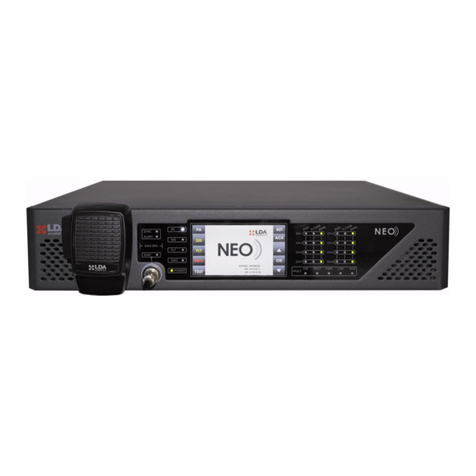
LDA Audio Tech NEO Series User manual
LDA Audio Tech
LDA Audio Tech Neo VAP 1 User manual
LDA Audio Tech
LDA Audio Tech NEO Series User manual
Popular Security System manuals by other brands

Safe-at-home
Safe-at-home security system quick start guide
Wittkopp
Wittkopp FinKey SL installation instructions
ROBENS
ROBENS DUNKERY instruction manual

Detection Systems
Detection Systems 7100 Quick reference guide
Interlogix
Interlogix ATS1235 Installation sheet
Lorex
Lorex VANTAGE LH110 ECO SERIES Product information
