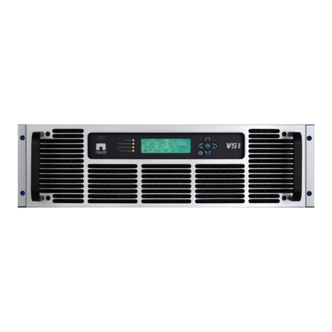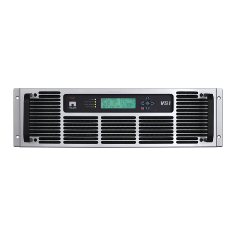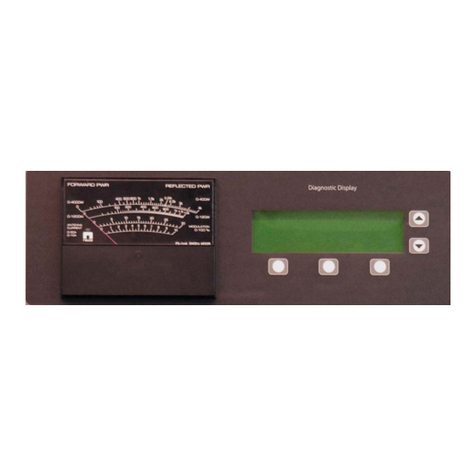
IS04013 Single ND500II (User Supplied Cabinet)
Information Sheet
1. INTRODUCTION
This document identifies the information
specific to a single ND500II radio beacon
transmitter installed in a user-supplied
cabinet. Information provided includes
cabinet requirements, installation, start-up
and calibration/testing procedures and
mechanical drawing (including dimensions).
2. CABINET REQUIREMENTS
The user supplied cabinet must be able to
house an ND500II radio beacon transmitter
and an optional remote control unit if desired.
In this document, the transmitter is
designated as unit 1 and the optional
computer remote control unit is designated as
unit 2. Refer to figures 1 and 2 for electrical
schematics of the transmitter system. Refer
to figure 3 for recommended equipment
layout.
3. INSTALLATION INFORMATION
Complete or verify the following
requirements are completed during
installation of the transmitter system.
NOTE
The following instructions include the
installation of a slide kit (Nautel Part #158-
8015). The slide kit allows the transmitter to
be pulled out of the user-supplied cabinet to
allow access to circuitry and to support the
weight of the transmitter. The transmitter
weighs approximately 41kg/90 lbs and
cannot be supported by only the
transmitter’s front panel mounting holes. If
the slide kit is not used, suitable provision
must be taken to support the transmitter in
the cabinet. The installation of the drawer
mounting slides will vary depending on the
cabinet and may require modification to fit.
(a) Ensure the cabinet will not topple, when
the transmitter is extended on its drawer
slides, by securely bolting the cabinet to
its mounting surface.
(b) Install the slide mounting brackets (from
slide kit, Nautel Part # 158-8015) in the
user-supplied cabinet (see Figure 3).
Ensure the mounting brackets are
secured, level and correctly positioned to
allow transmitter installation.
(c) Install the drawer slides (from slide kit,
Nautel Part # 158-8015) as shown in
Figure 3.
(d) Install the transmitter in the cabinet (using
the drawer slides).
(e) Connect appropriate AC power source
wiring (115 VAC, 60Hz or 230 VAC
50/60Hz) to 1U2 on the rear of the
transmitter.
(f) If used, connect external 24 or 48V
power source wiring as detailed in the
ND500II manual. It will be necessary to
temporarily remove the transmitter’s rear
cover. Retain hardware to re-install
cover at the end of the installation
procedure.
(g) If used, connect external control/monitor
wiring to the transmitter’s terminal block
or D-sub connectors as detailed in the
ND500II manual.
NOTE
Refer to the ND500II transmitter manual for
instructions on enabling and disabling the
remote power trim feature.
If the optional remote control unit (unit 2) is
installed, refer to its service instruction
manual for detailed information regarding
remote control inputs/outputs.
Single ND500II (User Supplied Cabinet) – IS04013 Page 1
Information Sheet Issue 1.0
