MicroAir Avionics M760 User manual

Microair Avionics Pty Ltd
Airport Drive
Bundaberg
Queensland 4670
Australia
Tel: +61 7 41 553048
Fax: +61 7 41 553049
e-mail: sales@microair.com.au
Microair Avionics M760 Transceiver Installation & User Manual
M760Q Install & User Manual 01R12.doc Page 2 of 36 30th March 2010
About This Document
This manual describes the various installation configurations
available for the Microair M760 Transceiver. The
Transceiver’s controls and design features are described and
illustrated.
This is a controlled document and may not be amended,
copied or distributed, without the prior consent of Microair
Avionics Pty Ltd.
© Microair Avionics Pty Ltd
Ensure that the M760 transceiver is switched off during
engine starting and stopping to avoid damage occurring.
CURRENT REVISION STATUS
Revision Date Change
K 31/01/00 Initial release
L 18/11/01 Additional install data and wiring diagram added
M 04/10/02 Additional wiring diagram added
N 08/12/03 Updated for revision N
P 01/10/06 Updated for revision P
01R3 13/10/06 Updated for proposed functionality of revision P
01R4 30/05/07 Proposed functionality for revision P amended
01R5 28/06/07 Updated for functionality as of M760_MICRO_1-3-3
01R6 3/06/08 Warranty Statement Upgrade
01R7 08/12/08 Updated for revision P2
01R8 25/2/09 Updated Limited Warranty Statement & deleted Warranty cards
01R10 24/4/09 Updated for revision Q
01R11 13/07/09 Additional Installation data added
01R12 30/03/10 Drilling template updated

Microair Avionics M760 Transceiver Installation & User Manual
M760Q Install & User Manual 01R12.doc Page 3 of 36 30th March 2010
TABLE OF CONTENTS
1.0 INTRODUCTION......................................................................................................................................4
2.0 UNPACKING..............................................................................................................................................4
2.1 USER / INSTALL MANUAL.................................................................................................................................................4
2.2 NAMEPLATE DETAILS........................................................................................................................................................4
2.3 AUTHORISED RELEASE CERTIFICATE...........................................................................................................................4
3.0 INSTALLATION .......................................................................................................................................5
3.1 WIRING...................................................................................................................................................................................6
3.2 COAX TERMINATION .........................................................................................................................................................8
3.3 ANTENNA ..............................................................................................................................................................................8
3.3.1 METAL SKIN AIRFRAMES................................................................................................................................................................9
3.3.2 NON-METAL SKIN AIRFRAMES......................................................................................................................................................9
3.4 POWER..................................................................................................................................................................................10
3.4.1 BACKLIGHTING...............................................................................................................................................................................10
3.4.2 POWER SAVINGS.............................................................................................................................................................................10
3.5 MICROPHONE .....................................................................................................................................................................11
3.5.1 ELECTRET.........................................................................................................................................................................................11
3.5.2 DYNAMIC..........................................................................................................................................................................................11
3.6 SPEAKER..............................................................................................................................................................................11
3.7 INTERNAL VOX INTERCOM............................................................................................................................................12
3.8 HEADSET ADJUSTMENT..................................................................................................................................................12
3.8.1 SIDETONE.........................................................................................................................................................................................12
3.8.2 MIC GAIN..........................................................................................................................................................................................12
3.9 EXTERNAL INTERCOM.....................................................................................................................................................13
3.10 DUAL COMM INSTALLATION.........................................................................................................................................13
3.11 AUXILIARY AUDIO ...........................................................................................................................................................14
3.12 DATA INTERFACE (SL30).................................................................................................................................................15
3.12.1 TRANSCEIVER FUNCTION.............................................................................................................................................................16
3.12.2 TRANSCEIVER STATUS..................................................................................................................................................................16
3.13 PC INTERFACE....................................................................................................................................................................16
3.14 NOISE SUPPRESSION.........................................................................................................................................................17
3.14.1 POWER FILTER ................................................................................................................................................................................17
3.14.2 FERRITE CHOKES............................................................................................................................................................................17
4.0 OPERATIONAL CONTROLS...............................................................................................................18
4.1 PRIORITY SWITCH.............................................................................................................................................................19
4.2 VOLUME / SQUELCH KNOB ............................................................................................................................................19
4.3 ANNUNCIATOR LED .........................................................................................................................................................19
4.4 MODE SWITCH....................................................................................................................................................................20
4.5 TOGGLE SWITCH ...............................................................................................................................................................20
4.6 FREQUENCY ADJUST KNOB ...........................................................................................................................................21
4.7 REMOTE MEMORY BUTTON...........................................................................................................................................22
4.8 PUSH TO TALK BUTTON..................................................................................................................................................22
5.0 OPERATIONAL MODES ......................................................................................................................23
5.1 ACTIVE/STANDBY MODE................................................................................................................................................23
5.1.1 108 TO 118 MHZ TUNING................................................................................................................................................................23
5.2 MONITOR FUNCTION........................................................................................................................................................24
5.3 CHANNEL MODE................................................................................................................................................................26
5.4 VOX MODE ..........................................................................................................................................................................27
6.0 PROGRAM MENU..................................................................................................................................28
6.1 CD LOCKOUT......................................................................................................................................................................28
6.2 VOX.......................................................................................................................................................................................29
6.3 MONITOR SETUP................................................................................................................................................................29
6.4 NEW MEMORY CHANNEL ...............................................................................................................................................30
6.4.1 SET FREQUENCY.............................................................................................................................................................................30
6.4.2 SET LOCATION ................................................................................................................................................................................30
6.4.3 SET SERVICE....................................................................................................................................................................................30
6.5 EDIT MEMORY CHANNEL ...............................................................................................................................................31
6.6 EXIT MENU..........................................................................................................................................................................31
7.0 WIRING DIAGRAM...............................................................................................................................32
8.0 SPECIFICATIONS M760Q....................................................................................................................33
9.0 DRILLING TEMPLATE........................................................................................................................34
10.0 LIMITED WARRANTY.........................................................................................................................35
Microair Avionics M760 Transceiver Installation & User Manual
M760Q Install & User Manual 01R12.doc Page 4 of 36 30th March 2010
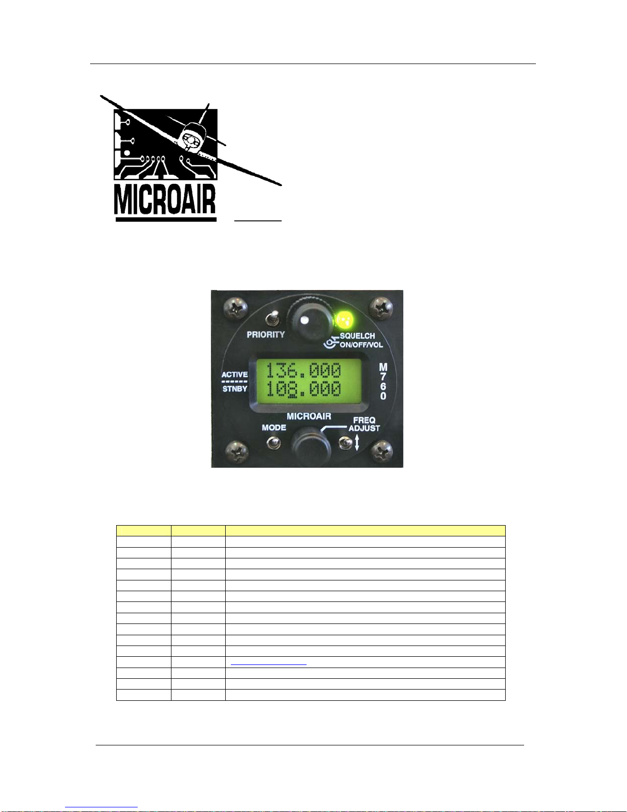
1.0 INTRODUCTION
Thank you for purchasing this Microair product. The M760 is a 760 channel VHF aircraft transceiver, packaged
to fit a standard 57mm (2 ¼”) instrument hole. The M760 has been produced in accordance with CASA APMA
approval E2000-004.
2.0 UNPACKING
The M760 is boxed in polystyrene for physical protection, and wrapped in an anti-static bag for electrical
protection. Once the box is opened and the radio unwrapped, the owner is responsible for physical and
electrical protection.
Enclosed with the radio are: User / Install Manual
CASA form 1 – release certificate
DB15 solder plug and backshell
2.1 USER / INSTALL MANUAL
Please read this manual completely before attempting to install or operate this radio. There are several
installation options you may wish to consider, which are clearly laid out in the installation section.
IMPORTANT NOTE
This manual may be used as technical data to support an installation
under the FAA form 337 process.
The M760 has all of the basic radio operations, and many other management and programming options,
which are described in the operation and memory sections of this manual.
Please refer to the Microair Avionics Website www.microair.com.au for more installation information.
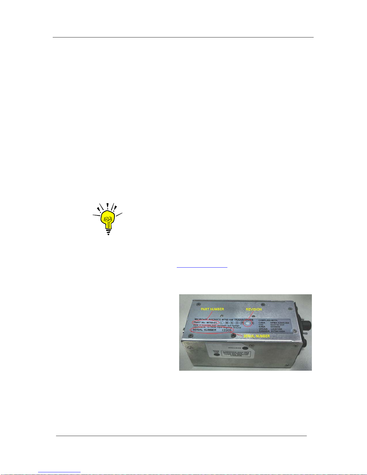
2.2 NAMEPLATE DETAILS
The M760 has a nameplate fixed to the
bottom plate of the chassis.
The Nameplate records the M760’s part
number, revision, and serial number.
Microair recommends the M760 serial
number be noted in the aircraft’s
maintenance records for future reference.
2.3 AUTHORISED RELEASE CERTIFICATE
The CASA form 1 – release note is an internationally recognised document which clearly identifies the
part/component the form 1 is associated with. Please keep this certificate with the aircraft’s file or log
book.
Microair Avionics M760 Transceiver Installation & User Manual
M760Q Install & User Manual 01R12.doc Page 5 of 36 30th March 2010
3.0 INSTALLATION
The M760 has a simple physical installation for aircraft instrument panels. Select or cut a 57mm (2 ¼”)
instrument hole for mounting (refer panel drilling template in section 9.0).
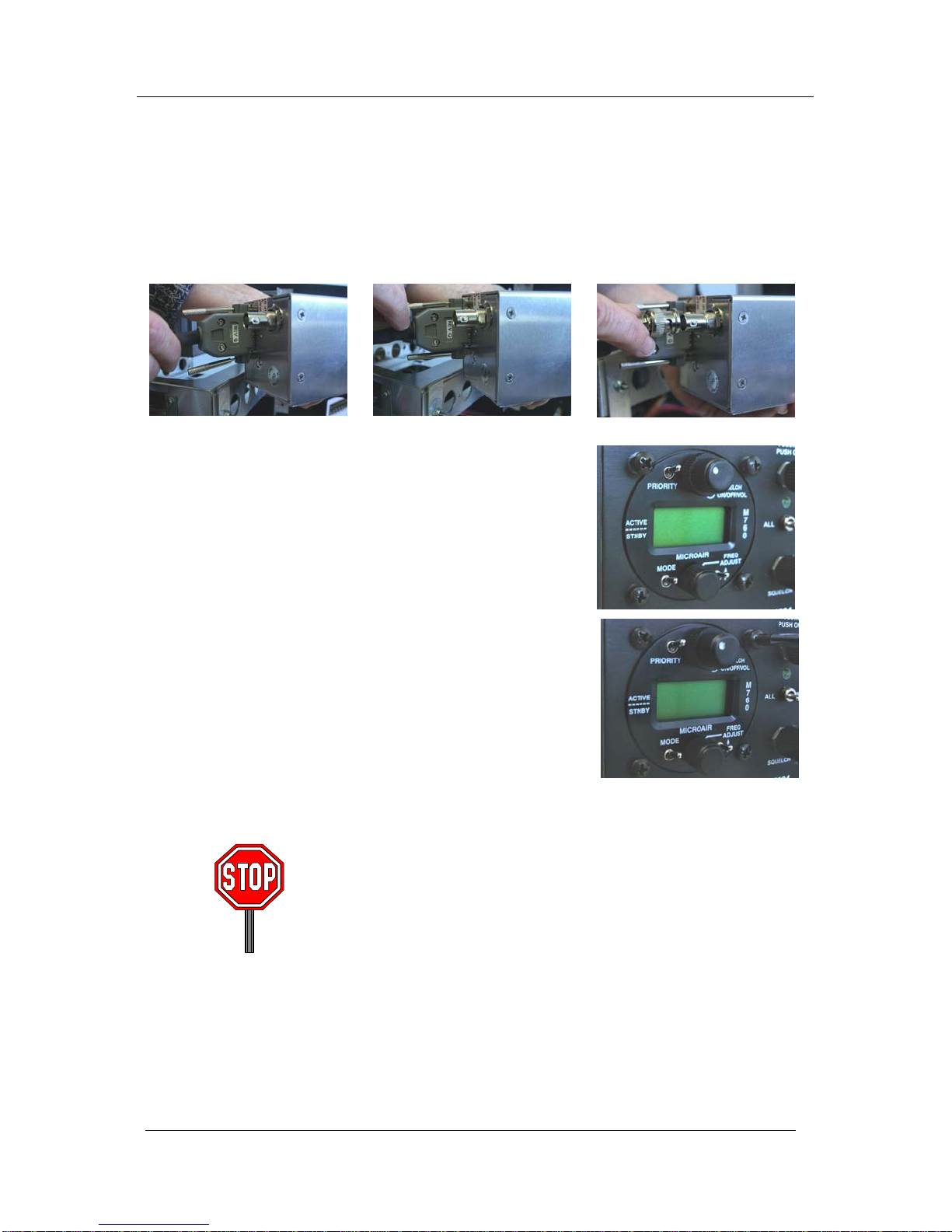
For panel locations which do not afford sufficient space behind the radio to reach the connectors, Microair
recommends connecting the wiring harness and coax cable before fitting the radio to the hole in the panel.
Present the M760 to the rear face of this hole. The stepped round face
will insert through the hole, and should appear flush with the front of
the instrument panel when correctly positioned. Rotate the M760 to
align the four M4 machine screws.
Loose fit all four M4 screws. For installations where the existing
instrument panel screw holes are 1/8”, the holes will need to be
enlarged to 5/32” to fit the M4 machine screws.
Insert and tighten all four M4 machine screws. The M760 requires no
rear support, the M4 screws provide all of the physical mounting
required.
The M760 should be located in the aircraft within view of the pilot
seated in the pilot-in-command position, and afford this pilot good
access to the front face controls.
Do NOT oversize the mounting holes in the front face of the radio,
to an imperial size. Drilling will damage internal components.
Do NOT replace the M4 machine screws supplied with the radio
with longer screws. Over-length screws will touch or even crush
internal components and cause damage.
Either of these actions will void the warranty
Other manuals for M760
2
Table of contents
Other MicroAir Avionics Transceiver manuals


Popular Transceiver manuals by other brands

Kenwood
Kenwood ProTalk TK-3201 instruction manual

City Theatrical
City Theatrical SHoW DMX SHoW Baby user manual

Standart Horizont
Standart Horizont HX407 owner's manual

B&G
B&G V90S quick start guide

VictelGlobal
VictelGlobal ALK300 series Operation manual

Cactus
Cactus Wireless Flash Transceiver V6 user manual


