MicroAvionics PM100 User manual

Part No. MP001-BT
Part No. MP001A-BT
‘PM100’
Side Tone
RadioHeadset
USER
MANUAL
V3.0 Dated: 25/01/2017
Ship Farm, Horsley, Derby DE21 5BR. ENGLAND
Tel +44 (0) 1332 880468, Fax +44 (0) 1332 882640
sales@microavionics.com
www.microavionics.com
User Manual
Important
Please read these instructions in full before use. There are some user settings that
may require pre-setting before use. Damage may be caused if you do not set the
headset for your radio.
The MicroAvionics PM100 headset has been designed for high noise environments and
offers state of the art electronic noise filtering coupled together with an extremely high
quality noise cancelling microphone. You will be able to hear and transmit clear
signals even in the harshest environment.
The headset can be worn under a MicroAvionics EN966 certified aviation helmet. Our
helmets come in four sizes. We always recommend you use our helmet.
The headsets have been designed to produce high quality music. The radio volume
should be kept high and the headset volume should be low. If you inadvertently set the
headset volume high then you will hear a small amount of bleed through side tone in
your headset, thus we recommend a low headset volume setting to cancel this out.
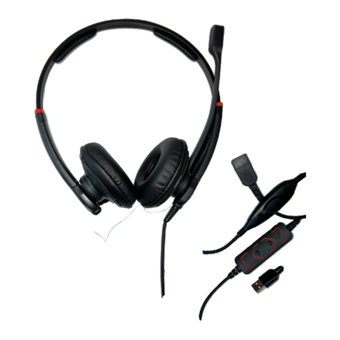
PM 100 Headset
The PM100 headset is designed to work with most radios. The headset can easily be user
configured to work with most radios without the need of opening up the headset to adjust the
electronics. The user simply adjusts the position of some hidden DIP switches to configure
the headset for the radio type (e.g. Airband to PMR radio).
You can connect a single auxiliary input lead to the headset, or buy a remote splitter box
which enables you to connect up to 5 remote cables to the headset.
The headset has a side tone. Side tone enables the user to hear them self talk whilst
transmitting. This stops the user from shouting and enables the receiving party to hear you
easily without distortion. There is a built in muting circuit safety feature. If you are listening to
music, telephone or second radio and the MASTER radio receives a signal the other devices
will mute. This gives priority to the master radio for safety reasons.

Features & Functions
•Muting circuit, cuts out music, telephone & second radio when master radio receives
a signal.
•Side tone, hear your own voice on transmit.
•Stereo Music giving superb sound.
•Stereo Line out for recording sound.
•Mobile telephone connection.
•User can configure the headset to work with most radios.
•Use two radios at once (i.e. Airband and PMR).
•PTT on headset.
•Digital Volume dial on headset.
Accessories.
Mobile telephone lead – Sometimes requires base adapter (ask for more information)
Stereo Music lead
Line Out sound recording lead
Auxiliary second radio lead
Remote PTT lead
Splitter box lead for more than one accessory lead
Automobile 12 volt charging lead
In aircraft 12 volt charging lead
Adapters for converting twin jack radio lead to single jack lead.
Icom A5, A23 require CT44 adapter
Vertex/ Yaesu VXA radios require LA44 adapter
Vertex/ Yaesu VX Radios require CT44 adapter
Charging.
There is a DC power jack on the right hand ear cup. This accepts 9 to 14 volts. Connect the
supplied power supply to the headset and leave on charge for up to 20 hours. Alternatively
you can connect any 12 volt lead to the headset from your aircraft or automobile’s power
supply. We can supply extra charging leads on request. The batteries are NiMH. These have
no memory effect and you can part charge the batteries if required. If your headset is not flat
do not charge for 20 hours, instead charge for lesser time. You can discharge the batteries
quickly by plugging a music source to the headset and leave playing until the batteries are
flat, then charge for 20 hours.
Battery condition Indicator LED.
There is a charge indicator LED next to the on/off switch. When the LED is ‘ON’ the power
switch will be in the on position. When the LED is ‘OFF’, either the power switch is ‘off’ or the
batteries are low. The headset can be used when the LED fades off, but the battery condition
is low and should be charged. The headset can be charged with the switch in ‘on’ or ‘off’
position.
How to use the headset.
1. Check the DIP switch position with the chart 1 below.
2. First turn the power switch on, this can be found inside the left hand ear cup. You
must turn this off when not in use.
3. Connect your device (radio, MP3 etc.) to the headset.
4. Set volume dial. Do this by asking for a ‘radio check’. Be very careful; the volume in
the headset can be turned high so you must check the volume levels before flight.
5. When the headset is not in use turn the power switch ‘OFF’.
Bluetooth – Streams music and telephone calls.
Turn headset power ON. Search for Bluetooth on your telephone and pair to MicroAvionics
once found. Telephone will auto answer after 1-2 rings.
Connecting auxiliary inputs
Stereo Music Input. When connecting an MP3 player you need to connect the locking bayonet
lead to the headset. Turn the headset power switch ‘ON’.Set the volume levels before flight.

You will enjoy high quality STEREO sound. Please see table 2 switch 1 for your preferred
music setting.
Mobile Telephone. Connect the locking bayonet lead to the headset. Some telephones will
accept the 2.5mm stereo jack plug, most telephones require a ‘BASE ADAPTER’ (available
from us/ your Microavionics agent)The audio levels may need user configuring depending on
what telephone you have. If you transmit on the telephone a low or too strong signal or you
receive a too low or high signal you should reconfigure the settings as per table 2, switches
11 & 12. You can also adjust the receive volume on most telephones prior to adjusting the
headset level adjustment.
Second radio. You should specify the second radio make and model on ordering so you buy
the correct lead. Connect the second radio lead to the headset using the locking bayonet
connector. To transmit you must turn the headset power switch ‘ON’. Now press the PTT
switch on the RADIO and speak into the headset. You can adjust the transmitted audio level,
see Table 2, switch 7 for more information.
Remote PTT. Connect the remote PTT lead to the headset using the locking bayonet
connector. Velcro the switch housing to a suitable surface. Press on hold the switch to
transmit.
Stereo Line Out for Sound record. Connect the lead to the headset using the locking bayonet
connector. Connect the audio lead to your audio recorder (camcorder, etc). Turn the headset
power ‘ON’. You should make sure your recording device accepts Line out audio levels before
connecting.
Tandem connecting lead. Used to connect two PM100 headsets together for tandem use. To
transmit you press the PTT button. To activate the intercom, turn switch 3 to ON, for solo
flying turn ‘OFF’.
Table 1
The below table shows the user settings for each radio type. If your radio is not listed then
please contact us before use, damage may be caused if you set 8.9 & 10 incorrectly. The
settings marked in blue can be user set, these alter various thresholds. Switches 8, 9 & 10
alter the radio configuration. Once set you can reset alter the settings at any time.
Radio
>>Switch
1
2
3
4
5
6
7
8
9
10
11
12
Icom A6, A24
Off
On
Off
On
On
Off
Off
Off
On
Off
On
Off
Icom A3, A4, A5, A22,
A23,
Off
Off
Off
Off
Off
Off
Off
Off
On
Off
On
Off
Icom A2, A20, ,A21
Off
Off
Off
Off
Off
Off
Off
Off
Off
On
On
Off
Kenwood TH22, Intek
Special cable.
Off
Off
Off
Off
Off
Off
Off
Off
On
Off
On
Off
Motorola
Special Cable.
Off
Off
Off
Off
Off
Off
Off
Off
Off
On
On
Off
2m band & PMR band
Alinco, Icom Yaesu 2m
band, Midland G7
Off
Off
Off
Off
Off
Off
Off
Off
Off
On
On
Off
Yaesu / Vertex
FT10R, to FT50R
VX1R to VX152,VX3
Off
Off
Off
Off
Off
Off
Off
Off
Off
On
On
Off
Yaesu / Vertex
VXA100 to VXA210
Off
Off
Off
Off
Off
On
Off
Off
On
Off
On
Off
VXA & VX radios require adapters
Icom A5, A23 require CT44 adapter
The below table shows the different user settings that can be made to your headset. It is
important that you fully understand what each setting does. Changing an incorrect switch will
render the headset un-usable until the correct settings are made. If you make an incorrect
setting you should consult the corresponding table to reset your headset back to factory set
conditions for your type radio being used.

You can access the small set of DIP switches via the window in the left hand ear cup.
Carefully remove the blank plate with a small screwdriver. After this is removed you will see a
small row of 12 switches. To change the switch position carefully flick the switch with a small
screwdriver. Take care not to break the switches.
Table 2.
1
EQ Gain
On = Reduces wind noise. Not as
good for music.
Off= Treble noise. Better for music. Not as
good for amplified wind noise.
2
Mic Gain 1
On
Off
Mic Gain Level
Low
High
3
Tandem Intercom
ON
Intercom ON
OFF
Intercom OFF
4
Mute Sensitivity
On = Higher Radio volume to Mute
Off = Lower Radio volume to mute
5
TX Level 1
On
On
Off
Off
Transmit Levels
Very Low
Low
Medium
High
6
TX Level 2
On
Off
On
Off
7
Second Radio Mic o/p
level
On = Low mic o/p level
Off = High mic o/p level
8
PTT type
On = Hard Ground
Off = Resistive ground (for most radios)
9
Mic Ring
On = Audio on Ring
If 10 is on leave 9 off
10
Mic Tip
On = Audio on Tip
If 9 is on leave 10 off
11
Mobile TX Level
On = Higher TX level
Off = Lower TX level
12
Mobile RX Level
On = Low Receive level
Off = Higher Receive level
Blue
Switch
Intercom Side tone
On = Side tone on always, Us this
for tandem/ Biplace intercom
Off = Side tone only on TX
Switch 1: This alters the equalisation (EQ). For better music reproduction it is best for this to
be in the off position (more treble). If you fly a fast aircraft and suffer from wind noise then this
switch should be in the On position, this reduces treble and reduces amplified wind noise. It is
unlikely that you will need this in the On position.
Switch 2 : This alters the minimum and maximum microphone gain. We recommend the Low
setting. If you suffer from low mobile or radio transmit levels then turn this setting towards the
high level as this will give a stronger signal. Be careful, if you set this too high you may hear a
feedback squeal in the headsets.
Switch 5 & 6: This adjusts the TX (transmit) level on the master radio. To set this to optimum
setting you will need two radios.
Test 1.Transmitt from one radio to the other. Note the receive level (no headset connected).
Test 2. Now transmit from the headset and note the receive level.
You should try to match the volume of test 2 with test 1. If test 2 is lower then set switch 5&6
to a higher level or vies versa.
Switch 7: This adjusts the Auxiliary radio transmit output (o/p) level. Adjust in a similar way to
switch 5&6 only this setting is either High or Low (2 settings).
Switch 8: This selects the PTT type either hard ground or resistive. You should use resistive
PTT setting first as this works for most radios. If your radio does not transmit then try setting
the Hard PTT (On). Most radios will require the Off position.
Switch 9 & 10: This changes the mic transmit from ring to tip. You must not have both
switches on together. Please follow the radio table for more information.
Switch 11: Adjusts the transmit level of the mobile telephone.
This manual suits for next models
4
Table of contents
