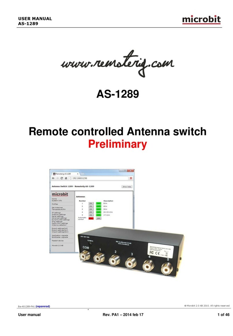
Microbit AS-1269 User manual

USER MANUAL
m crob t
AS-1269
Ba-AS1269-PA4.docx
Microbit 2.0 AB 2010. All rights reserved
a
User manual
Rev. PA4 –2017 Okt 17
1 of 51
AS-1269
Remote controlled Antenna switch

USER MANUAL
m crob t
AS-1269
Ba-AS1269-PA4.docx
Microbit 2.0 AB 2010. All rights reserved
a
User manual
Rev. PA4 –2017 Okt 17
2 of 51
Table of contents
Statement of Conditions..............................................................................4
General Description.....................................................................................5
Step by step AS-1269 setup ........................................................................6
Hardware ....................................................................................................8
Bottom ......................................................................................................... 8
Top ( under the top cover) ............................................................................. 9
Configuration with Microbit Setup Manager ..............................................12
FW/HW ....................................................................................................... 13
FW update................................................................................................... 14
Setup ......................................................................................................... 15
Net info....................................................................................................... 16
Initial IP setup ..........................................................................................17
Configuration with WEB-interface .............................................................21
Set Antennas ............................................................................................... 23
Inputs......................................................................................................... 23
Temperature/RH .......................................................................................... 24
IP Settings .................................................................................................. 26
Antenna settings .......................................................................................... 29
Serial Settings ............................................................................................. 30
Advanced settings ........................................................................................ 31
Dynamic DNS setting.................................................................................... 33
Remoterig dynamic dns service...................................................................... 34
DynDNS dynamic DNSservice ........................................................................ 36
Ping Settings ............................................................................................... 38
Radio RRC Settings....................................................................................... 40
Antenna selection......................................................................................... 41
Application firmware upgrade ........................................................................ 43
Bootloader firmware upgrade......................................................................... 44
Restart device.............................................................................................. 44
Networks and Firewalls.............................................................................45
Portforwarding ............................................................................................. 46
Appendix D –Manual Antenna Switch .......................................................47
Appendix E - Technical Data ......................................................................49
Appendix F - Safety and Regulatory Information ......................................50

USER MANUAL
m crob t
AS-1269
Ba-AS1269-PA4.docx
Microbit 2.0 AB 2010. All rights reserved
a
User manual
Rev. PA4 –2017 Okt 17
3 of 51
FCC Statement ............................................................................................ 50
Safety Notice ............................................................................................... 50
Disclaimer ................................................................................................... 51
FCC / CE - Declaration of conformity............................................................... 51

USER MANUAL
m crob t
AS-1269
Ba-AS1269-PA4.docx
Microbit 2.0 AB 2010. All rights reserved
a
User manual
Rev. PA4 –2017 Okt 17
4 of 51
Statement of Conditions
In the interest of improving internal design, operational function, and/or reliability, Microbit
2.0 AB reserves the right to make changes to the product described in this document without
notice. Microbit does not assume any liability that may occur due to the use or application of
the product(s) or circuit layout(s) described herein.
All parts of the software are property of Microbit 2.0 AB. The hardware design, schematics
PCB layout, concept, graphics, user manual, etc. are property of Microbit 2.0 AB. The device
may not be disassembled, copied or reversed engineered.
Copyright © 2010,2011,2012,2013
Microbit 2.0 AB
All rights reserved.

USER MANUAL
m crob t
AS-1269
Ba-AS1269-PA4.docx
Microbit 2.0 AB 2010. All rights reserved
a
User manual
Rev. PA4 –2017 Okt 17
5 of 51
General Description
The Antenna switch is designed specially to be used for remote (over the Internet) controlled
systems, but can of course be used in other applications also. The switch can be manually
controlled via an internal web interface. The switch is connected to the Internet primarily via
10 or 100 Mbit Ethernet and fixed connections like DSL, cable and WLAN or 3G/4G Mobile
systems. The Switch is easily configured via modern USB and WEB based user interfaces.
Together with Remoterig RRC-1258 it can be setup to automatically follow your band
changes. The switch connects to the RRC over IP, no serial port is needed. It can be powered
with 48V via the Ethernet cable according to the PoE standard or with 12 DC. This means that
the switch can be placed in a tower up to 100m from the schack. The switch is built in
stainless steel and can be placed outdoor. It’s normally delivered with SO-239 connectors, but
can be ordered with N-connectors, both with PTFE dielectric.

USER MANUAL
m crob t
AS-1269
Ba-AS1269-PA4.docx
Microbit 2.0 AB 2010. All rights reserved
a
User manual
Rev. PA4 –2017 Okt 17
6 of 51
Step by step AS-1269 setup
Below follows a recommendation about how to proceed when setting up the system.
1. Spend some time to read thru this user manual to get familiar with the product.
2. Remove the top cover of your Antenna Switch.
3. Check that the Jumper JMPx is in the EXT position.
4. Apply 12V DC (good stabilized power) to the unit, either via the 2.1/5,5 DC-jack or via
the screw terminals, (see hardware chapter)
5. Connect the unit with a CAT5 patch cables to the same Ethernet switch or router as
your PC which you will use to setup the system is connected. Do not bother with the
cables through the inlet in the bottom of the Antenna switch until you have set it up
and tested that you can control it via the webbrowser.
6. Download the Microbit Setup Manager and the latest firmware from
http://www.remoterig.com to your PC. Follow the instructions about how to install the
Microbit Setup Manager (see chapter Configuration with Microbit Setup Manager).
7. Find out how your network is configured and configure the AS-1269 to fit into your
network (see chapter Initial IP Setup) with the Microbit Setup Manager.
8. Check the installed firmware version. If the one you downloaded from Remoterig is
newer, update the unit with the new firmware. (see chapter FW/HW about how to
update).
9. When you have configured the unit to fit into your network, Start your Web browser
and connect to the unit by entering the IP-address. If you get in contact with the
internal web server everything is OK.
10. Make the basic software configuration for your system which is described the later in
this user manual.
11. Nov you have to decide how you should use the switch. If you should power it via 12V
DC or via Power over Ethernet. If you will use PoE you can disconnect your 12V source
and move JMPx on the 1269B pcb to the PoE positon. Connect your LAN cable either
to the RJ45 jack marked LAN or to the screw terminals on the 1269B PCB. Now you
can use the inlet in the bottom of the Switch to make a more permanent installation.
The screw terminals are marked with the standard colors of CAT5/6 cables. Be very
careful if you use the screw terminals, Interchanging the wire can damage both the
Antenna switch and the PoE supply. Microbit do not take any responsibility of
damaged units or connected equipment.

USER MANUAL
m crob t
AS-1269
Ba-AS1269-PA4.docx
Microbit 2.0 AB 2010. All rights reserved
a
User manual
Rev. PA4 –2017 Okt 17
7 of 51
12. After preparing the cables connect them to the controlled equipment. Connect the
power to all equipment. Check with your web browser again that you are in contact
with unit and can control the connected equipment.
13. When everything works as it should on your local network it’s time to setup your
Internet router so you can reach the unit from the outside world over the Internet. If
you already have other equipment that you remote control you can go direct to 14 as
you don’t need to use a separate Dynamic DNS service.
14. The first thing is to determine if your Internet Service Provider (ISP) are providing you
with a fixed or dynamic IP-address. Fixed IP:s are rare so you probably have a
dynamic IP-address if you are not paying extra for a fixed one. A dynamic IP is no
problem but you need to use a dynamic DNS service. You can use Remoterigs free
dynamic DNS service or a DynDNS account. New DynDNS account are no longer free.
For detailed information about Dynamic DNS services see the Dynamic DNS chapters
under Configuration with WEB-Interface.
15. Configure the units Dynamic DNS settings (see chapter Dynamic DNS Setting).
16. Now it’s time to configure your remote router. We recommend that you first enable the
remote configuring of your router, you may need it later. After that’s done configure
port forwarding (see chapter Network and Firewalls). When this is done your remote
control unit should be reachable over the Internet.
17. When back at the Control QTH try to browse to the Dynamic DNS address “Own host
name” you registered and entered into the remote control unit. You should get in
contact with the Antenna Switch internal web server exactly as it was local, remember
to use :port number after the dyndns address if you have changed the webserver port
from 80 for example http://sm2oan.mine.nu:8000.
Enjoy the remote controlling.

USER MANUAL
m crob t
AS-1269
Ba-AS1269-PA4.docx
Microbit 2.0 AB 2010. All rights reserved
a
User manual
Rev. PA4 –2017 Okt 17
8 of 51
Hardware
Bottom
On the bottom side the antenna connectors are located according to the pictures above. The
antenna switch is normally delivered with SO-239 jack but can also be ordered with N
connectors. The ventilator will prevent moisture to build up in the housing.

USER MANUAL
m crob t
AS-1269
Ba-AS1269-PA4.docx
Microbit 2.0 AB 2010. All rights reserved
a
User manual
Rev. PA4 –2017 Okt 17
9 of 51
Top ( under the top cover)
To reach the different connectors the top cover have to be removed. The top cover is secured
to the bottom by 8 stainless steel M3 screws.
Power
The Antenna switch can be power in three different ways depending on your installation. If
you install it indoor or where power is available you can connect 12V DC power direct to the
Antenna Switch, if you install it at the foot of the tower for example, Power Over Ethernet can
be handy to use.
1. Via the 2.1/5.5 DC jack on the 1216H pcb (see picture). In this case the JMP should be in
the Ext Pwr position.
12V DC

USER MANUAL
m crob t
AS-1269
Ba-AS1269-PA4.docx
Microbit 2.0 AB 2010. All rights reserved
a
User manual
Rev. PA4 –2017 Okt 17
10 of 51
Pin no
PWR
+
+ 12-15VDC (centre)
-
GND
2. Via the screw terminals on the 1269B pcb (see pictures). In this case the JMP should be in
the Ext Pwr position.
The terminals are marked with + and - .
3. Via 48V Power over Ethernet. In this case the JMP should be in the PoE position.
You can use a separate PoE Power Injector or use a switch with PoE output. In both cases the
power should be applied to the terminals according to the info below. The RJ45 LAN jack is
handy to use when setting up the system, while the screw terminals are recommended for
permanent installation. If you use the RJ45 for permanent use remember to connect the
screen to the screw terminal marked Shield
Pin
no
Screw term
Ethernet (RJ45)
1
Orange/white
Out [+]
2
Orange
Out [-]
3
Green/White
In [+]
4
Blue
+ 48V DC
5
Blue /White
+ 48V DC
6
Green
In [-]
7
Brown/White
- 48V DC
8
Brown
- 48V DC
USB
The USB-interface is used to initially set up the IP parameters. It can also be used for
downloading new software (can also be done via the WEB-interface). A USB-cable is included
with the product.
ETHERNET

USER MANUAL
m crob t
AS-1269
Ba-AS1269-PA4.docx
Microbit 2.0 AB 2010. All rights reserved
a
User manual
Rev. PA4 –2017 Okt 17
11 of 51
The unit can be connected to both 10 and 100 Mbit/s Ethernet based TCP/IP network. The
Antenna Switch can be configured for different connection types for Ethernet port, Auto,
10HDX, 10FDX, 100HDX, 100FDX and Auto-with-preferred-10FDX. Default is Auto-with-
preferred-10FDX which works best in most cases. The Ethernet cable can be connected via
the RJ45 LAN jack or via the screw terminals as described under PoE above.
ON LED
A Green flashing LED beside the USB connector on the 1216H pcb is indicating normal status.
STATUS LED
A Green flashing LED on the 1269B pcb indicates that the communication between the both
pcbs are OK. It will flash fast until the connection is up, and when everything is OK it changes
to slow flashing (1per/sec).
LINK LED
A yellow LED besides the Ethernet connector on the 1216H pcb indicates the status of the
Ethernet interface
LNK
Yellow LED indicates link OK, flashing LED indicates traffic

USER MANUAL
m crob t
AS-1269
Ba-AS1269-PA4.docx
Microbit 2.0 AB 2010. All rights reserved
a
User manual
Rev. PA4 –2017 Okt 17
12 of 51
Configuration with Microbit Setup Manager
The initial settings of the network parameters are easiest done with the Microbit Setup
Manager. The Setup Manager is a software which runs under Windows on a PC and connects
to the ANTENNA SWITCHvia USB (an USB cable is supplied with the AS-1269).The Setup
Manager can be used for:
•IP Settings and verification
oIP-address
oNetmask
oGateway
oDNS
oDHCP
•Firmware upgrade
oApplication
oBootloader
oFactory default reset
Start with downloading the Microbit Setup Manager from the homepage www.remoterig.com.
Install the Setup Manager by following the instructions which shows up. If you have an older
Windows version where Netframework 2.0 is not installed, the installer will guide you through
the installation of Netframework. When you have finished the installation a new shortcut to
Microbit Setup Manager will show up on the desktop. Click on the icon to start Microbit Setup
Manager
Connect your AS1269 to 12V and connect the USB-cable between your computer and the USB
jack on the 1216H pcb. Windows will automatically install the necessary drivers. When it's
done the text in the bottom field will change from "1216 not connected" to "1216-connected"
which is an indication that you are in connection with the unit.

USER MANUAL
m crob t
AS-1269
Ba-AS1269-PA4.docx
Microbit 2.0 AB 2010. All rights reserved
a
User manual
Rev. PA4 –2017 Okt 17
13 of 51
FW/HW
Click on the "Get" button and the version of the firmware will show up in the upper window.
Go to the page www.remoterig.com and under downloads you can find the latest firmware. If
there is a newer firmware available download it to your desktop, unzip it.
Change to the "FW-update" tab.

USER MANUAL
m crob t
AS-1269
Ba-AS1269-PA4.docx
Microbit 2.0 AB 2010. All rights reserved
a
User manual
Rev. PA4 –2017 Okt 17
14 of 51
FW update
Click on the "Select file" button and browse to the file with the new firmware, it should be
something like “1216H-CRC_v1.23_2011-10-04.bin” depending on the version and release
date. When you have selected the file click on the "Update" button and the update process
will start, the text in the bottom field will change to "Updating firmware". Attention -- Do not
interrupt the update process in any way!
After about a 1 minute the update is finished and the Antenna Switch will restart. When the
text "RC-connected" shows up again in the lower field of the Microbit Setup Manager, you can
change to the "FW/HW" tab and check software version.

USER MANUAL
m crob t
AS-1269
Ba-AS1269-PA4.docx
Microbit 2.0 AB 2010. All rights reserved
a
User manual
Rev. PA4 –2017 Okt 17
15 of 51
Setup
A new window wills pop-up with the basic IP settings. Change the settings so they fit into your
local network and press the "Save" button to save the new settings. The ANTENNA
SWITCHwill restart again and when the text "1216-connected" shows up again in the lower
field of the Setup-Manager, you can click on the "Setup" button again to verify the changes.

USER MANUAL
m crob t
AS-1269
Ba-AS1269-PA4.docx
Microbit 2.0 AB 2010. All rights reserved
a
User manual
Rev. PA4 –2017 Okt 17
16 of 51
Net info
Click on the “Get” button to read the IP setting currently in use by the Switch.

USER MANUAL
m crob t
AS-1269
Ba-AS1269-PA4.docx
Microbit 2.0 AB 2010. All rights reserved
a
User manual
Rev. PA4 –2017 Okt 17
17 of 51
Initial IP setup
The default Ip settings from the factory is 192.168.0.236. The net mask is 255.255.255.0,
gateway and DNS is 192.168.0.1.
To be able to contact the AS-1269 via the network you must configure the units to fit into
your home network. You can check your network configuration from your PC.
On the start menu select Run. In the Run dialog box enter cmd.
You will get a DOS-window.
At the DOS-promt enter ipconfig.
Then you will get the needed information:
Your PC IP address in this example is 192.168.0.101 this means that the IP of the AS-1269
must have IP:s in the area 192.168.0.2 to 192.168.0.255.

USER MANUAL
m crob t
AS-1269
Ba-AS1269-PA4.docx
Microbit 2.0 AB 2010. All rights reserved
a
User manual
Rev. PA4 –2017 Okt 17
18 of 51
The Netmask is 255.255.255.0 the Netmask in the RC-AS1269should be the same
The Default gateway 192.168.0.1 the Gateway and DNS server(*) in the ANTENNA
SWITCHshould be the same
In this case all the default IP setting will be OK.
(*) In most cases the Gateway and the DNS server is the same and the IP of the router.

USER MANUAL
m crob t
AS-1269
Ba-AS1269-PA4.docx
Microbit 2.0 AB 2010. All rights reserved
a
User manual
Rev. PA4 –2017 Okt 17
19 of 51
In another network, this is the result of the ipconfig command.
Your PC IP address in this example is 192.168.128.10 this means that the IP of the AS-1269
must have IP:s in the area 192.168.128.2 to 192.168.128.255.
The Netmask is 255.255.128.0 this the Netmask in the ANTENNA SWITCHshould be the same
The Default gateway is 192.168.128.1 the Gateway in the AS-1269 should be the same
In this case you must change the IP:s of the RC.
Use the Microbit Setup Manager to change the IP settings.
Select the Setup tab click on the “Get Setup” button and enter the IP addresses in the Setup
info dialog box.

USER MANUAL
m crob t
AS-1269
Ba-AS1269-PA4.docx
Microbit 2.0 AB 2010. All rights reserved
a
User manual
Rev. PA4 –2017 Okt 17
20 of 51
Table of contents
Other Microbit Switch manuals
Popular Switch manuals by other brands

FS
FS STP Series Configuration guide

Cisco
Cisco Cisco mds 9124 - fabric switch Specifications

Optex
Optex OAM-DUAL T Operation manual

ADTRAN
ADTRAN NetVanta 900 Series quick start guide

ZyXEL Communications
ZyXEL Communications GS-105A Specifications

LIBERTY AV SOLUTIONS
LIBERTY AV SOLUTIONS DIGITALINX DL-SC31U-BX owner's manual