manuals.online logo
Brands
  1. Home
  2. •
  3. Brands
  4. •
  5. Assa Abloy
  6. •
  7. Switch
  8. •
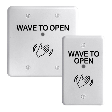
  9. Assa Abloy Norton Wave to Open 704 User manual

Assa Abloy Norton Wave to Open 704 User manual

Other Assa Abloy Switch manuals

Assa Abloy Aperio AH40 User manual

Assa Abloy

Assa Abloy Aperio AH40 User manual

Assa Abloy Aperio AH15 User manual

Assa Abloy

Assa Abloy Aperio AH15 User manual

Assa Abloy Aperio Quick setup guide

Assa Abloy

Assa Abloy Aperio Quick setup guide

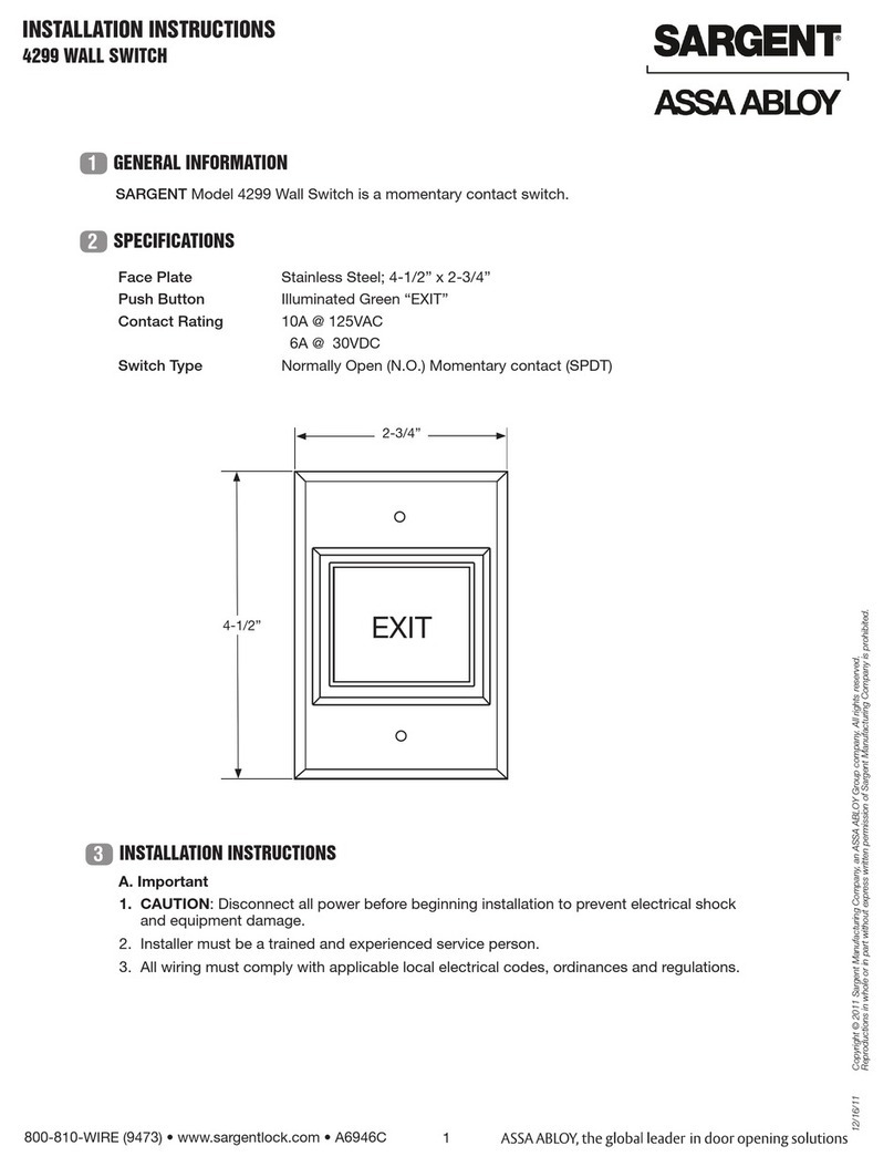
Assa Abloy Sargent 4299 User manual

Assa Abloy

Assa Abloy Sargent 4299 User manual

Assa Abloy aperio AH20 GEN5 User manual

Assa Abloy

Assa Abloy aperio AH20 GEN5 User manual

Assa Abloy Securitron WSS Wave Sense User manual

Assa Abloy

Assa Abloy Securitron WSS Wave Sense User manual

Assa Abloy Securitron WSS Manual

Assa Abloy

Assa Abloy Securitron WSS Manual

Assa Abloy Aperio AH20 User manual

Assa Abloy

Assa Abloy Aperio AH20 User manual

Assa Abloy Aperio AH30 User manual

Assa Abloy

Assa Abloy Aperio AH30 User manual

Assa Abloy Securitron SP-1 User manual

Assa Abloy

Assa Abloy Securitron SP-1 User manual

Assa Abloy Norton 564 User manual

Assa Abloy

Assa Abloy Norton 564 User manual

Assa Abloy Aperio User manual

Assa Abloy

Assa Abloy Aperio User manual

Assa Abloy Aperio AH20 User manual

Assa Abloy

Assa Abloy Aperio AH20 User manual

Assa Abloy Aperio AH40 User manual

Assa Abloy

Assa Abloy Aperio AH40 User manual

Popular Switch manuals by other brands

SMC Networks SMC6224M Technical specifications

SMC Networks

SMC Networks SMC6224M Technical specifications

Aeotec ZWA003-S operating manual

Aeotec

Aeotec ZWA003-S operating manual

TRENDnet TK-209i Quick installation guide

TRENDnet

TRENDnet TK-209i Quick installation guide

Planet FGSW-2022VHP user manual

Planet

Planet FGSW-2022VHP user manual

Avocent AutoView 2000  AV2000BC AV2000BC Installer/user guide

Avocent

Avocent AutoView 2000 AV2000BC AV2000BC Installer/user guide

Moxa Technologies PT-7728 Series user manual

Moxa Technologies

Moxa Technologies PT-7728 Series user manual

Intos Electronic inLine 35392I operating instructions

Intos Electronic

Intos Electronic inLine 35392I operating instructions

Cisco Catalyst 3560-X-24T Technical specifications

Cisco

Cisco Catalyst 3560-X-24T Technical specifications

Asante IntraCore IC3648 Specifications

Asante

Asante IntraCore IC3648 Specifications

Siemens SIRIUS 3SE7310-1AE Series Original operating instructions

Siemens

Siemens SIRIUS 3SE7310-1AE Series Original operating instructions

Edge-Core DCS520 quick start guide

Edge-Core

Edge-Core DCS520 quick start guide

RGBLE S00203 user manual

RGBLE

RGBLE S00203 user manual

Thrustmaster FLIGHT SIMULATOR X quick guide

Thrustmaster

Thrustmaster FLIGHT SIMULATOR X quick guide

Southwire SURGE GUARD 41390 RVC troubleshooting guide

Southwire

Southwire SURGE GUARD 41390 RVC troubleshooting guide

Buhler Nivotemp NT 61 Brief instructions

Buhler

Buhler Nivotemp NT 61 Brief instructions

Kramer VS-41HDCP user manual

Kramer

Kramer VS-41HDCP user manual

Techly IDATA AU-270 user manual

Techly

Techly IDATA AU-270 user manual

Belkin F1U109 user manual

Belkin

Belkin F1U109 user manual

manuals.online logo
manuals.online logoBrands
  • About & Mission
  • Contact us
  • Privacy Policy
  • Terms and Conditions

Copyright 2025 Manuals.Online. All Rights Reserved.

Copyright © 2020, ASSA ABLOY Accessories and Door Controls Group, Inc. All rights reserved. Reproduction in whole or
in part without the express written permission of ASSA ABLOY Accessories and Door Controls Group, Inc. is prohibited.
80-9370-0002-020 Rev 2 07/20
Model 704 Wave to Open Switch
1-3/4" Wide Jamb Mounting
Installation Instructions
1/8"
Bit
Phillips
Drive Bit
Drill
Step
Bit
Flat Head
Screwdriver
Phillips Head
Screwdriver
Safety Glasses
Center
Punch Pencil Deburring
Tool
Wire Stripper/
Cutter
Tape Measure
This product can expose you to lead which is known to the state of
California to cause cancer and birth defects or other reproductive harm.
For more information go to www.P65warnings.ca.gov.
WARNING
Components Supplied Fasteners Tools Needed
Conduit supplied by others
This unit is not supplied with a radio frequency transmitter.
If a transmitter is added, a deeper surface mounted box,
supplied by others, will be needed.
2x
M3 x 8.3mm Philips
Flat Head Machine
Screw
4x
#8 Phillips Round
Head Metal
Drilling Screw
Conduit
Housing
Wave to Open
Switch
M3 Screw
#8 Screw
Specications:
Input Voltage: 12V to24VDC
SPDT Contact Rating: 2A @30VAC/VDC
Sensor Detection Range: Up to 4" (101mm)
Operating Temperature: -13° F to 131°F (-25°C to 55°C)
Current Draw: 50mA @12VDC, 65mA @24VDC
Approved 2020-07-09
Copyright © 2020, ASSA ABLOY Accessories and Door Controls Group, Inc. All rights reserved. Reproduction in whole or
in part without the express written permission of ASSA ABLOY Accessories and Door Controls Group, Inc. is prohibited.
80-9370-0002-020 Rev 2 07/20
2
Model 704 Wave to Open Switch
Power
+
N/C
C
N/O
Power -
Wiring:
For proper wire connection, loosen
screws fully and ensure silver contact
is completely down. Insert wires and
tighten screws to secure wires.
1 Sec 5 Sec 10 Sec 15 Sec 20 Sec 25 Sec 30 Sec 35 Sec
LED Setting:
Time Delay Setting:
Jumper in place: LED is
Red and ashes Green
when relay is active.
No Jumper: LED is
Green and ashes Red
when relay is active.
31 "-/4
( mm)83
13 "-/4
( mm)44.5
15/16"
(24.2mm)
5/8"
(16mm)
1-3/8"
( mm)34.9
4-1/2"
(115mm)
1-3/ "4
( mm)44.5
Ø 78/"
( mm)22
Ø 316/"
( mm)5
( places)6
3- 11/16"
(94mm)
13 16/"
( mm)20
Wave to Open Switch Conduit Housing
Approved 2020-07-09
Copyright © 2020, ASSA ABLOY Accessories and Door Controls Group, Inc. All rights reserved. Reproduction in whole or
in part without the express written permission of ASSA ABLOY Accessories and Door Controls Group, Inc. is prohibited.
80-9370-0002-020 Rev 2 07/20 3
Model 704 Wave to Open Switch
1. Place conduit housing on door jamb with
horizontal centerline between 34" - 48"
(86.4cm - 121.9cm) from oor. (Fig 1)
2. Using conduit housing as a template, mark
and center punch four (4) mounting holes and
conduit hole on door jamb.
3. Using 1/8" bit, drill four (4) mounting holes.
4. Using step drill, create a clearance hole for
conduit. Smooth conduit clearance hole with
deburring tool, if necessary.
Installation
Prepare Door Jamb
1. If required by local codes, attach wire conduit
(supplied by others) to back of housing and
feed wires through.
2. Align housing to mounting holes on door
jamb and secure with four (4) #8 Phillips
Round Head Metal Drilling screws. (Fig 3)
NOTE: Make sure housing is level.
Install Conduit Housing
1. Set LED and Time Delay Settings as desired on
Wave to Open switch. See “LED Setting” and
“Time Delay Setting”, page 2.
2. Use small at head screwdriver to connect
24VDC and activation wiring with terminal
block. (Fig 4) See “Wiring”, page 2 and
appropriate wiring diagram of door operator
instructions.
3. Attach Wave to Open switch to conduit
housing using two (2) M3 x 8.3mm Philips Flat
Head Machine screws. (Fig 5)
Install Switch Terminal
Block
34" (86.4cm) Min
48" (121.9cm) Max
1-3/4"
(m)
44.5m
Figure 1
Figure 2
Figure 3
Figure 4 Figure 5
LED and
Timing
Delay
Approved 2020-07-09
Norton is a brand associated with ASSA ABLOY Accessories and Door Controls Group, Inc., an ASSA ABLOY Group company.
Copyright © 2020, ASSA ABLOY Accessories and Door Controls Group, Inc. All rights reserved. Reproduction in whole or
in part without the express written permission of ASSA ABLOY Accessories and Door Controls Group, Inc. is prohibited. 80-9370-0002-020 Rev 2 07/20
Norton Technical Product Support:
Monroe, NC 28112 USA
Phone: 800.438.1951 ext: 6030
TechSupport.Norton@assaabloy.com
nortondoorcontrols.com
Two Modes:
Standby (default LED Red)
Operating (default LED ashing Green)
To operate switch, make a slow waving
motion with hand in front of plate within
4" (101mm).
When hand movement is detected or
backup button is pressed, a tone will
sound and LED circle will ash to indicate
relay has been activated. (Fig 6)
Relay will activate for amount of time as
set by time delay jumpers. Backup button
can be used to activate relay at any time.
(Fig 6)
LED
Backup
Button
Operation
Figure 6
Approved 2020-07-09