Microcare 12/1000 User manual

0
1Kw / 2Kw / 3Kw / 5Kw
PURE SINE WAVE
BI-DIRECTIONAL
INVERTER MANUAL

1
Contents
1. INTRODUCTION ............................................ 2
2. SAFETY INSTRUCTION ................................ 3
3. SYSTEM DESCRIPTION ............................... 6
4. INVERTER OPERATION ............................... 8
5. INVERTER PROGRAMMING ...................... 13
6. SPECIFICATIONS OF INVERTERS ............ 23

2
1. INTRODUCTION
1.1 GENERAL DESCRIPTION
The Microcare Pure Sine Wave Inverters deliver true clean sine wave output power.
The Power is applicable for any kind of load, such as air-conditioners, home
appliances, consumer electronics and office e uipment. This series features a durable
and continuous 24 hour operation. The compact and modular design makes utility
interactive installations easier and more cost effective. It is a high uality product that
offers the best price/performance ratio in the industry.
1.2 KEY FEATURES
1.2.1 Multiple microprocessor design base.
1.2.2 Compatible with both linear and non-linear loads.
1.2.3 24 hour operation of the inverter.
1.2.4 DC start and automatic self-diagnostic function.
1.2.5 THD less than 3%.
1.2.6 Internal high power 3 stage charger.
1.2.7 High efficiency design to save electricity.
1.2.8 Low heat dissipation for long time operation.
1.2.9 Designed to operate in a harsh environment.
1.2.10 Wall Mounted.
1.3 IMPORTANT NOTICES
• Read instructions carefully before operating Inverter.
• Inverter connection instructions must be followed.
• The unit should only be opened by skilled personal.
• Retain the load within in the rating of Inverter to prevent faults.
• Keep the Inverter clean and dry.
• If a 220vac supply is connected to the inverter and it is to be used as a UPS, then
the inverter can only supply its rated power.

3
2. SAFETY INSTRUCTION
2.1 POSITIONING
2.1.1 Do not put the Inverter on a rugged or inclined surface.
2.1.2
Do not install the Inverter near water or in damp environments.
2.1.3 Do not install the Inverter where it would be exposed to direct sunlight.
2.1.4 Keep the Inverter far away from heat emitting sources.
2.1. Do not block ventilation openings in the inverter housing.
2.1.6 Do not leave objects on top of the Inverter.
2.1.7 Do not expose the Inverter to corrosive gasses.
2.1.8 Ambient temperature: 0°C – 40°C.
2.2 INSTALLATION
MOUNT THE SINGLE HANGING BRACKET ONTO THE WALL.
SLIDE THE INVERTER OVER THE BRACKET SO THE INVERTER HANGS FROM THE
BRACKET.
2.2.1 Connect the Inverter AC OUTPUT only to an earthed DB Panel.
2.2.2 The AC connections are located at the top of the inverter under the top side cover.
(Where the Live and Neutral IN, Live and Neutral OUT and Earth Connections are.)
2.2.3 If a 220vAC supply or a generator is available, connect into the Live and Neutral IN
Connection.
2.2.4 Make sure the BATTERY INPUT CIRCUIT BREAKER is OFF.
2.2.5 Place cables in such a way that no one can step on or trip over them.
2.2.6 Battery cables must be a minimum of 35mm² and as short as possible.
2.2.7 The battery cables come out at the bottom of the inverter, next to the BATTERY
INPUT CIRCUIT BREAKER.
2.2.8 The unit must be mounted in a vertical position against the wall.
2.2.9 Minimum battery bank of 300A/Hours is suggested.
2.3 EARTHING OF EQUIPMENT
E uipment surge protection products are an effective way of controlling dangerous surges that
can enter a facility. When strategically placed and correctly installed, the Surge Protectors will
effectively reduce harmful over voltage conditions that can damage electrical and electronic
e uipment.
It is important that the protection system includes both structural and surge protection e uipment.
When lightning current passes into the ground through any conductor (Example: Tree Trunk) a
powerful electromagnetic force is set up due to the fast rise times of the strike. This
electromagnetic force then couples into any inductive loops that may be available in nearby
buildings. When these currents e ualize, damage usually occurs to the e uipment.

4
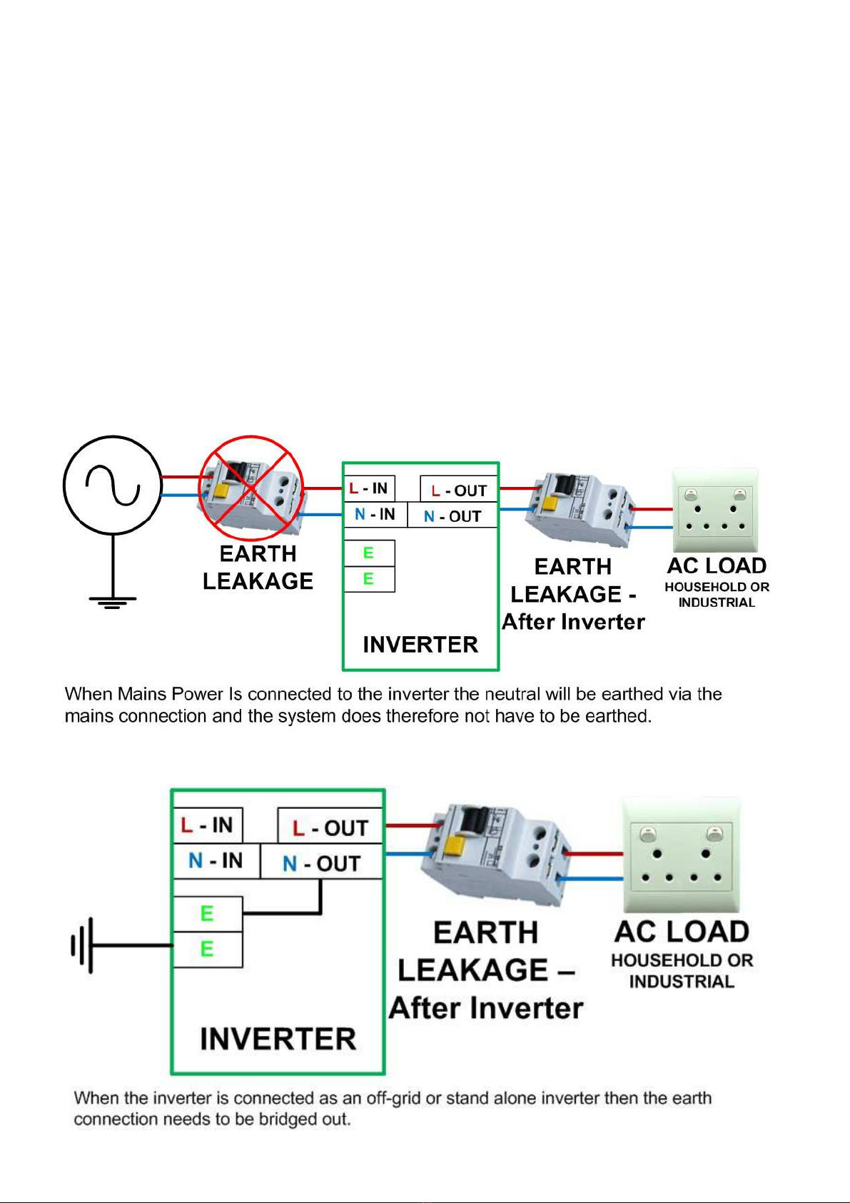
2.3.1 LIVE IN and N IN – Connect to Grid
2.3.2 LIVE OUT and N OUT – Connect to AC Load.
2.3.3 EARTH 1 – Connect to Earth Bar.
2.3.4 EARTH 2 – Connect to Chassis Earth.
The Microcare inverter is designed primarily for Grid / Mains connection to include charging.
When Mains is connected to the inverter the Neutral connection is Earthed via the Mains.
If the Inverter is connected as a stand-alone inverter with no Mains Connection, The Neutral
is re uired to be earthed using an earth spike.
If the Inverter is n t earthed; warranty will be null and v id.
5
2.3.5 Inverter Neutral Connection
The inverter has a floating neutral so the neutral voltage will be close to 110v. In this case
the live voltage with respect to the earth will also be around 110v.
If you use your inverter for a standalone application you need to bridge the neutral input
with the earth terminal on the inverter (these two are next to each other for this purpose).
You can now fit an earth leakage after the inverter.
But if you are going to supply your inverter with AC from the grid then you need to put the
inverter before the earth leakage and you need to keep the inverter neutral input connected
to the GRID neutral at all times.
So if you what to switch the GRID input to the inverter off then one must only switch live.
You can then put the earth leakage directly after the inverter. The grid will pull the inverter
neutral to 0v.
2.3.5 Inverter Earth Connection to Grid.
2.3.6 Inverter Earth Connection Off-Grid.

6
2.4 MAINTENANCE AND SERVICE
1. Caution – Risk of Electric Shock.
2. Batteries may cause electric shock and have a high short-circuit current. Please
take the precautionary measures specified below and any other measures
necessary when working with batteries.
• Remove wristwatches, rings and other metal objects.
• Use only tools with insulated grips and handles.
3. SYSTEM DESCRIPTION
3.1 SYSTEM DESCRIPTION. (1Kw; 2Kw; 3Kw a d 5Kw I verters.)
3.1.1 System Front View. (1Kw – 5Kw Inverters.)
3.1.2 System Back View. (1Kw – 5Kw Inverters.)

7
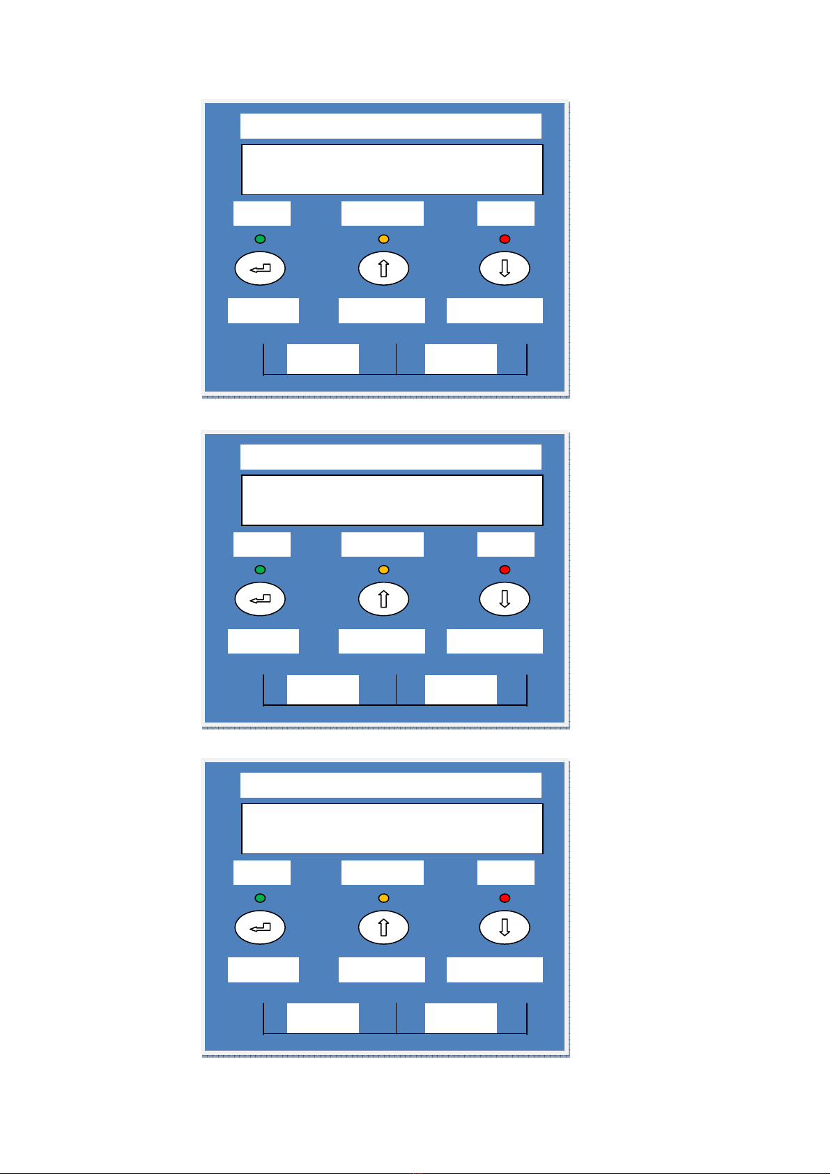
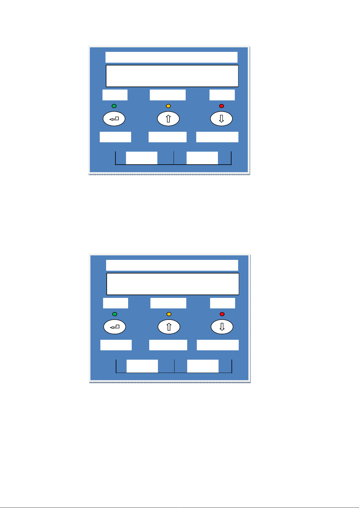
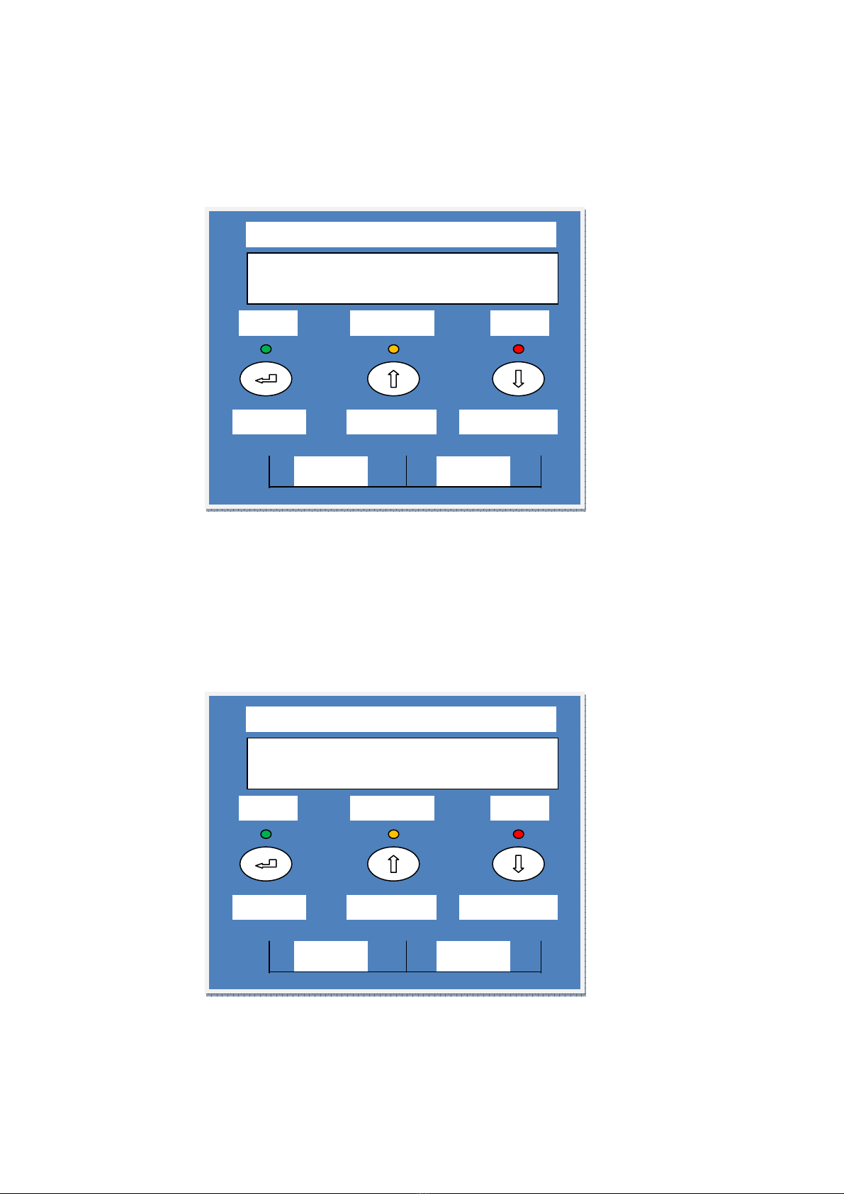
3.2 FRONT PANEL DESCRIPTION
3.2.1 LCD Display: This indicates the UPS’s operational information, including output
voltage, battery voltage, output load and inside temperature.
3.2.2 UP–Key: Use to move the display up.
3.2.3 DOWN–Key: Use to move the display down.
3.2.4 ENTER–Key: It is pressed with the UP–Key to turn on the UPS. Push the ENTER
button to confirm or store DATA.
3.2.5 Push the UP and DOWN keys together to turn off the inverter.
3.2.6 Fault LED (Red): To indicate the INVERTER is in a fault condition because of
inverter shutdown or over temperature.
3.2.7 Warning LED (Yellow): To indicate the INVERTER is in the status of overload or
battery LOW.
3.2.8 Normal LED (Green): To indicate the INVERTER is operating normally.
3.2 MAINTENANCE AND SERVICE
Wall mount unit.
8
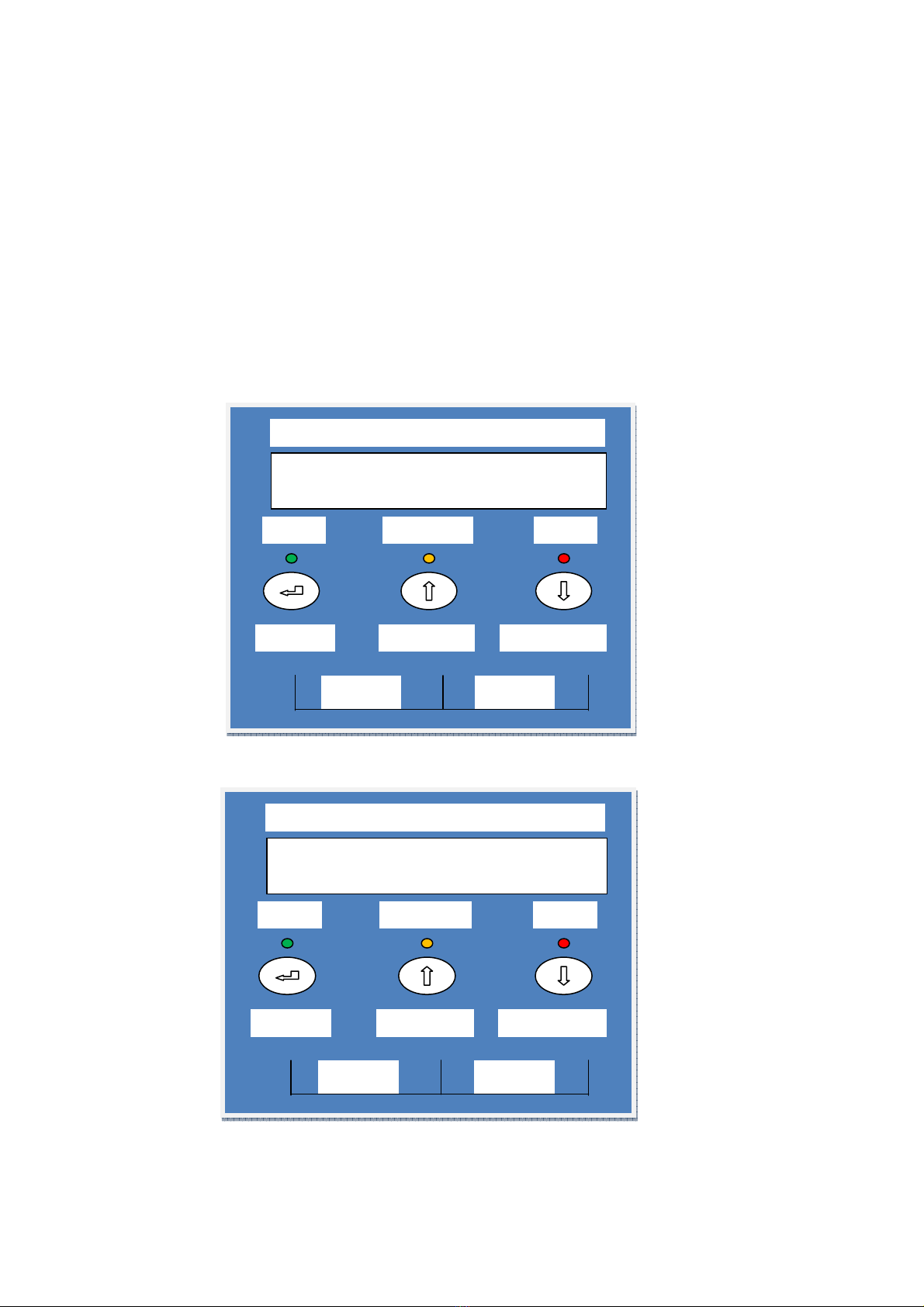
4. INVERTER OPERATION
4.1 Check Prior to Start Up
4.1.1 Ensure the INVERTER is mounted vertically.
4.1.2 Check Input and Output cables are secured.
4.1.3 Check if Battery voltage meets the INVERTER rating.
4.2
Operatio Procedure
Please follow the instructions below for the UPS operation.
Push and hold the RED PRECHARGE BUTTON until the Display comes on and shows
the following:
The display then changes to:
MICROCARE 5 KW
PERCENTAGE * %
MICROCARE
ON OFF
ENTER
Menu Down
Menu Up
OK
Invert
er
Error
MICROCARE UPS
…PLEASE WAIT…
MICROCARE
ON OFF
ENTER
Menu Down
Menu Up
OK
Inverter
Error
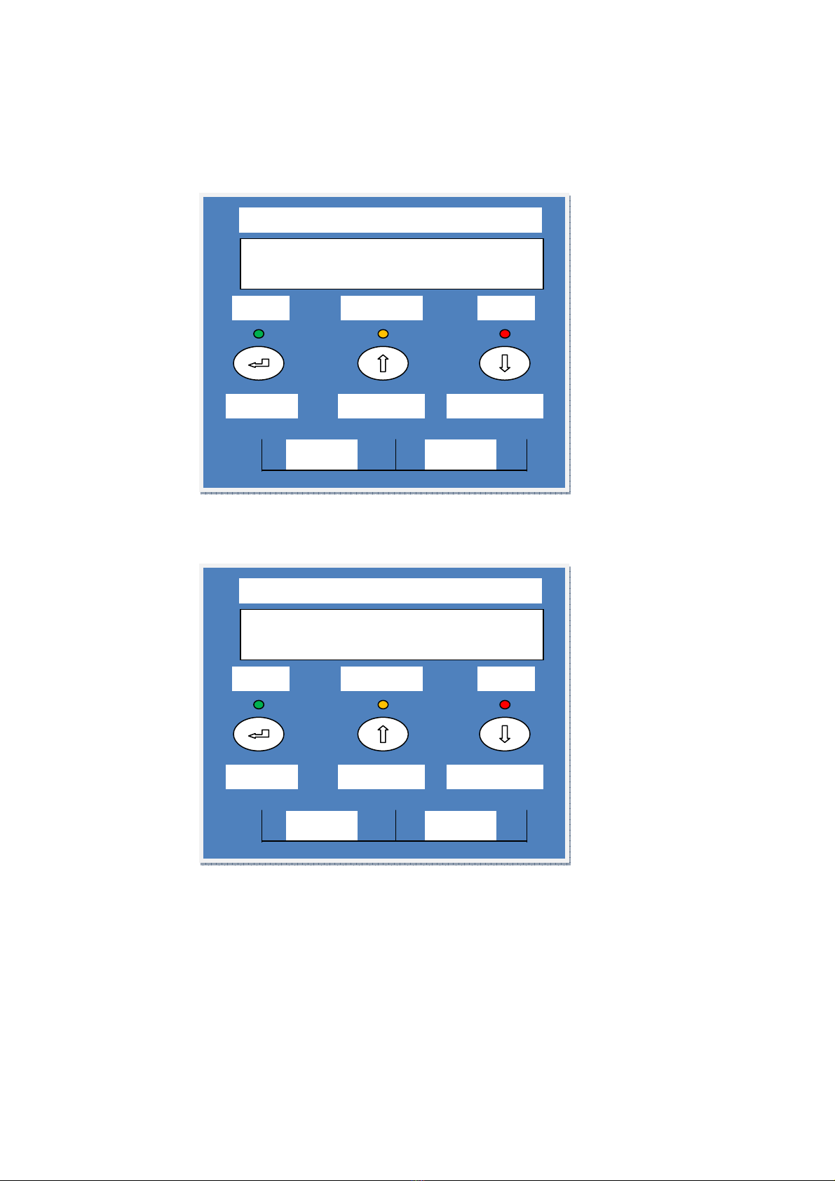
9
The display then changes to:
The display then changes to:
While holding in the PRECHARGE BUTTON turn on the MAIN CIRCUIT BREAKER.
UPS TURNED OFF
MICROCARE
ON OFF
ENTER
Menu Down
Menu Up
OK
Inverter
Error
UPS TURNED OFF
…CALIBRATING…
MICROCARE
ON OFF
ENTER
Menu Down
Menu Up
OK
Inverter
Error
10
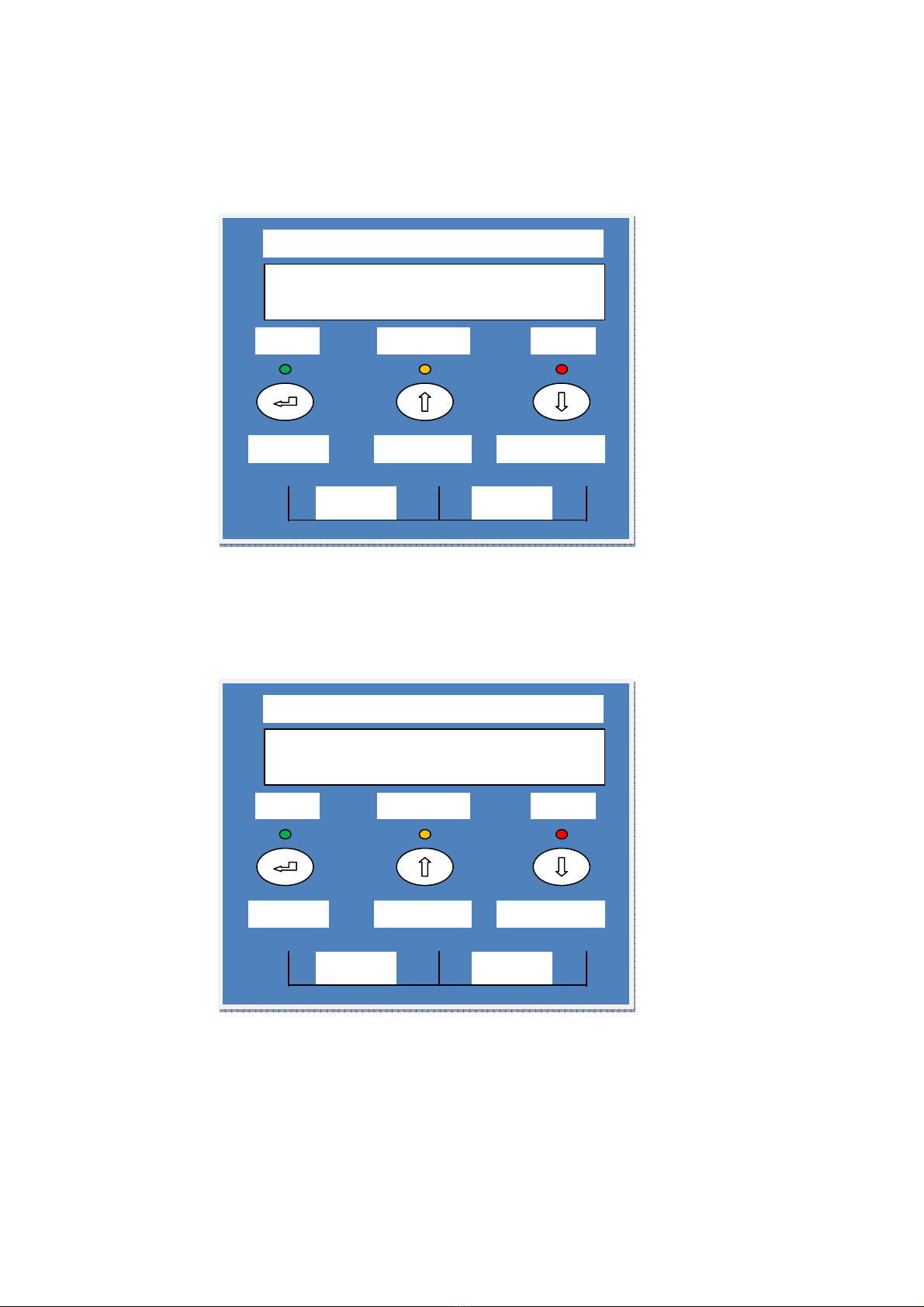
By pressing the Enter-key and the UP-key simultaneously for 3 seconds, the UPS will
start up and the OK LED will light up to indicate the power is being supplied from the
inverter to the load and the MAINS / FAIL LED comes ON. The display will show:
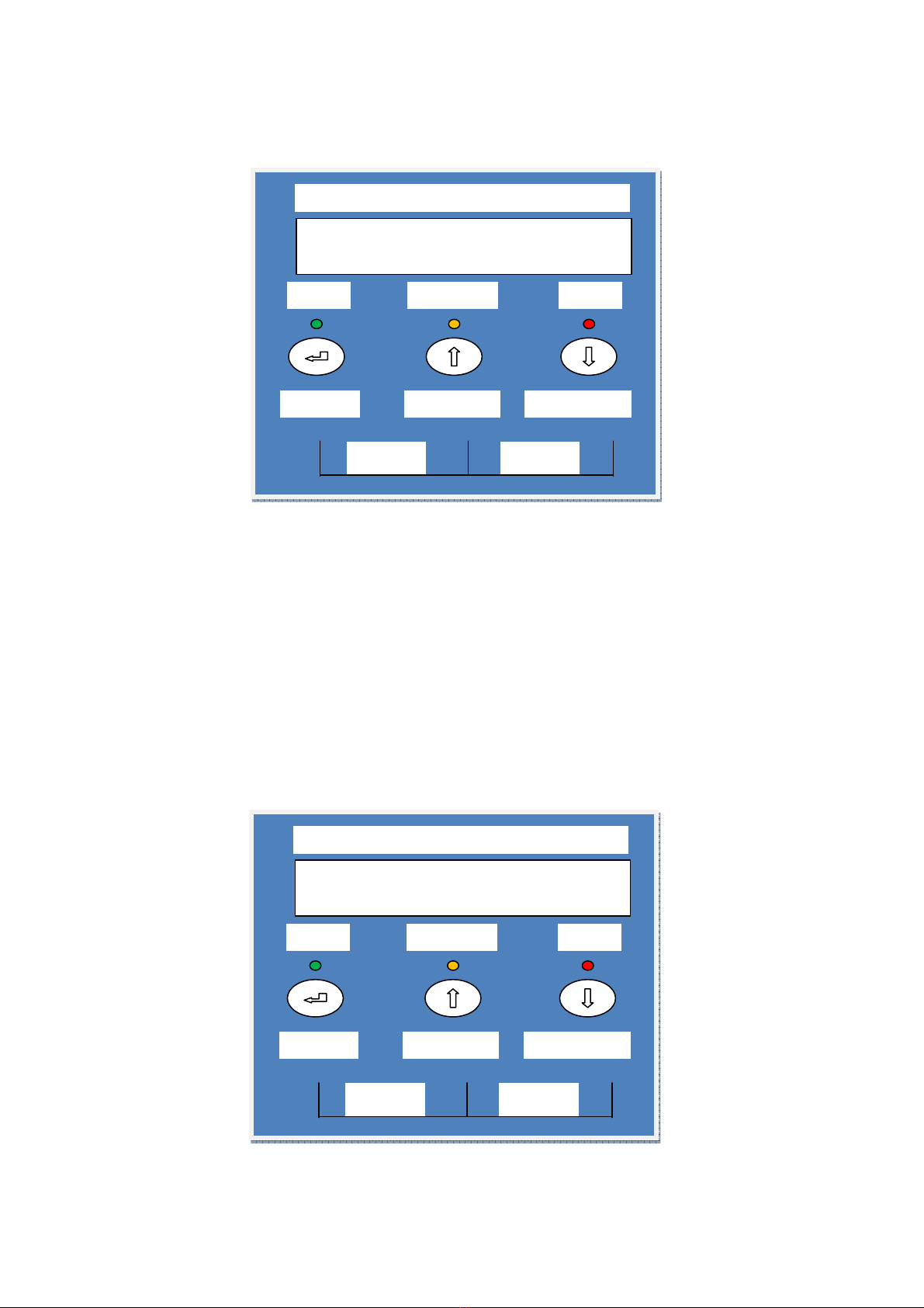
By turning on a load the OUTPUT % will change to indicate the amount of LOAD as a %
of the unit being used in KW.
When the Up-key and the Down-key are pressed simultaneously for 3 seconds, the UPS
will be turned OFF after two beeps.
LCD DISPLAY MENU
With the inverter in the ON position use the Up/Down keys to select menu-displays of the
LCD described below.
The screen will show the following:
INV TURNED ON Push the OK button.
Using the UP/D wn Buttons the following screens can be seen.
This shows the power rating of the UPS and its % output.
MICROCARE 5KW
INVERTER STANDBY
MICROCARE
ON OFF
E
NTER
Menu Down
Menu Up
OK
Inverter
Error
MICROCARE 5KW
INVERTER STANDBY
MICROCARE
ON OFF
ENTER
Menu Down
Menu Up
OK
Inverter
Error
11
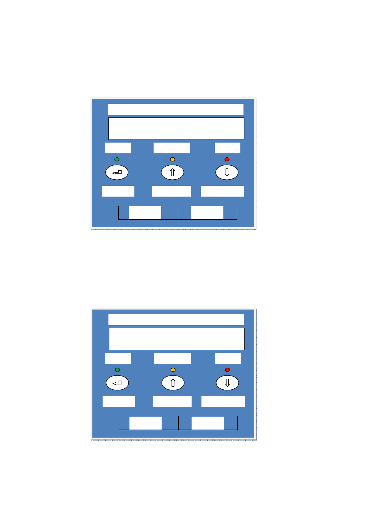
Using the UP arrows the following details can be checked:
This shows the battery voltage and the amps that the UPS is drawing from the battery.
This shows the output voltage and amps that the load is drawing from the Inverter.
This shows the internal temperature of the UPS.
TEMPERATURE
26.3 deg/cel
MICROCARE
ON OFF
ENTER
Menu Down
Menu Up
OK
Inverter
Error
UPS VOLTS : 220.0v
UPS AMPS : 0.0
MICROCARE
ON OFF
ENTER
Menu Down
Menu Up
OK
Inverter
Error
BATT VOLT : 54.0
BATT AMPS : 0.0
MICROCARE
ON OFF
ENTER
Menu Down
Menu Up
OK
Inverter
Error
12
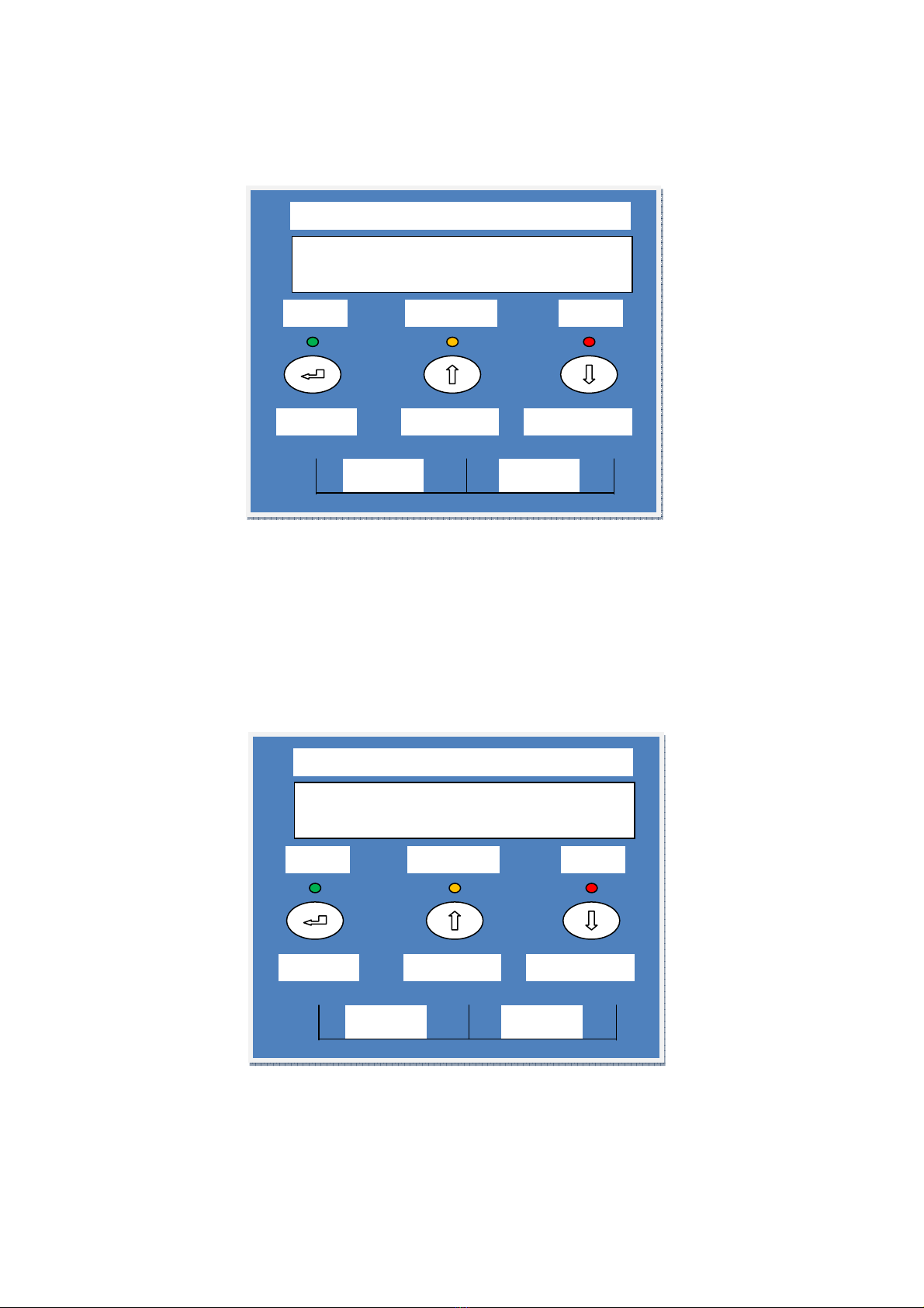
This shows that the control cards in the UPS have a 100% communication level.
This indicates the serial number of the Inverter.
SERIAL NUMBER:
MCxx007
MICROCARE
ON OFF
ENTER
Menu Down
Menu Up
OK
Inverter
Error
SIGNAL STRENGTH
DISPLAY-UPS 100%
MICROCARE
ON OFF
ENTER
Menu Down
Menu Up
OK
Inverter
Error
13
5. INVERTER PROGRAMMING
There are two MENUS’ which allow the user to change either the SET UP or the
BATTERY menus.
Push the UP / DOWN keys to select which menu is to be changed.
Push ENTER if you want to change the set up menu.
By pushing ENTER you can change whether the inverter runs in MANUAL mode;
AUTO mode or SOLAR mode. In the AUTO mode the inverter uses the least amount of
battery power when there is no load, however AUTO mode should only be used in remote
areas where power is not re uired constantly.
UPS MODE
MANUAL SENSE
MICROCARE
ON OFF
ENTER
Menu Down
Menu Up
OK
Inverter
Error
ENTER
SETUP MENU ?
MICROCARE
ON OFF
ENTER
Menu Down
Menu
Up
OK
Inverter
Error

14
Push the ENTER button. The menu changes to:
Push the ENTER button. The menu changes to:
In rder t run c rrectly in S lar C ntr l M de, the BATTERY OFF AT setup needs
t be changed in the BATTERY SETUP MENU t : (2V – 48V; 1.5V – 36V; 1V – 24V;
0.5V – 12V) Less than the BATTERY RUN TO Value setup in the SETUP MENU.
When the inverter is running in solar control mode and the Charge level is set to LEVEL 1,
the inverter will run the load using mains power and the solar regulator will charge the
battery bank. The inverter will switch back over to battery power when the AC RUN TO
Value is reached.
UPS MODE
AUTO SENSE
MICROCARE
ON OFF
ENTER
Menu Down
Menu Up
OK
Inverter
Error
UPS MODE
SOLAR CONTROL
MICROCARE
ON OFF
ENTER
Menu Down
Menu Up
OK
Inverter
Error
15
Push the UP button in SOLAR mode you can then access the battery run to menu:
(This allows the user to set the level the battery will go down to before switching to mains
power.)
Battery Run To: 48v System – 46v (Default) (Can be changed in 2v Increments)
36v System – 34.5v (Default) (Can be changed in 1.5v Increments)
24v System – 23v (Default) (Can be changed in 1v Increments)
12v System – 11.5v (Default) (Can be changed in 0.5v Increments)
Push the ENTER button. The Menu settings can be changed.
Push the UP button. The menu changes to AC RUN TO menu:
(Allows the user to set the level the mains will charge the battery to before the inverter
switches back to battery power.)
AC Run To: 48v System – 54.4v (Default) (Can be changed in 2v Increments)
36v System – 40.5v (Default) (Can be changed in 1.5v Increments)
24v System – 24v (Default) (Can be changed in 1v Increments)
12v System – 12v (Default) (Can be changed in 0.5v Increments)
Push the ENTER button. The Menu settings can be changed.
SOLAR
CONTROL
AC RUN TO 54.4v
MICROCARE
ON OFF
ENTER
Menu
Down
Menu Up
OK
Inverter
Error
SOLAR
CONTROL
BAT RUN TO 46.0v
MICROCARE
ON OFF
ENTER
Menu Down
Menu Up
OK
Inverter
Error
16
Push the UP button. The menu changes to:
This may be selected between LEVEL 1 which is the most sensitive to LEVEL 3 which is
the least sensitive by pushing the ENTER button.
To change the menu, push the UP button.
The menu will then change to:
The sensitivity of the OVERLOAD TRIP may be changed thru 5 LEVELS. The factory
default level is 2. Level 1 is HIGH and 2 is MEDIUM. These are instant trips. Levels 3 and
4 are HIGH and MEDIUM but have a 3 retry operation. If the inverter trips then it will try to
restart using a soft start mode. LEVEL 5 is LOW. Push ENTER to select the mode.
LOAD MONITORING
LEVEL (X) SELECTED
MICROCARE
ON OFF
ENTER
Menu Down
Menu Up
OK
Inverter
Er
ror
MAINS MONITORING
LEVEL 2 SELECTED
MICROCARE
ON OFF
ENTER
Menu Down
Menu Up
OK
Inverter
Error

17
Pushing the UP button will give you 3 options to SAVE the changed data. The display will
show:
EXIT, DO NOT SAVE
SET UP MENU ?
MICROCARE
ON OFF
ENTER
Menu Down
Menu Up
OK
Inverter
Error
RESTORE FACTORY
SET UP MENU ?
MICROCARE
ON OFF
ENTER
Menu Down
Menu Up
OK
Inverter
Error
EXIT AND SAVE
SET UP MENU ?
MICROCARE
ON OFF
ENTER
Menu Down
Menu Up
OK
Inverter
Error
18
If the changes to the settings need to be saved push ENTER if the enter button is pushed
for any of the above then the unit will show:
If no entry is made for 1 minute the display will return to the main menu and the back light will
turn off.
Use the UP button to select BATTERY menu:
ENTER
BATTERY MENU ?
MICROCARE
ON OFF
ENTER
Menu Down
Menu Up
OK
Inverter
Error
SAVING DATA TO
INTERNAL EEPROM
MICROCARE
ON OFF
ENTER
Menu Down
Menu Up
OK
Inverter
Error

19
To change the BATTERY CHARGE menu push ENTER, the following will show:
This allows the user to program the charge rate from 0 to 100%. LEVEL 4 is the factory
default. Level 1 is 0%, Level 2 is 5%, Level 3 is 25%, Level 4 is 50%, Level 5 is 75%,
Level 6 is 100%.
INVERTER CHARGE AMPS
1Kw12V 40A
1Kw24V 30A
1Kw36V 20A
1Kw48V 10A
2Kw12V 80A
2Kw24V 40A
2Kw36V 30A
2Kw48V 20A
3Kw24V 60A
3Kw36V 40A
3Kw48V 30A
5Kw24V 100A
5Kw36V 75A
5Kw48V 50A
Above is the list of charge amps for all of the inverters.
In regards to the battery charge level – The Level selected will allow the battery charge to
the batteries.
LEVEL 3 – 25% – On a 5Kw48V Inverter will allow a charge of 12.5A to the battery.
LEVEL 5 – 75% – On a 5Kw48V Inverter will allow a charge of 37.5A to the battery.
BATTERY
CHARGE
LEVEL (X) SELECTED
MICROCARE
ON OFF
ENTER
Menu Down
Menu Up
OK
Inverter
Error
This manual suits for next models
10
Table of contents
Other Microcare Inverter manuals


Popular Inverter manuals by other brands


-L1 user manual")
Huawei
Huawei SUN2000-(2KTL-6KTL)-L1 user manual

AIMS Power
AIMS Power PWRI8K22050 instruction manual

Mase
Mase IS3501 Usage and maintenance manual

Leroy-Somer
Leroy-Somer Powerdrive MD2R 100T Installation and Maintenance

Steamist
Steamist Plumbing Installation Instructions Plumbing installation instructions

Sungrow
Sungrow SC50HV Quick installation guide