Microcare Kaco User manual
KACO GRID TIED LIMITER
Single Phase & 3 Phase
User Manual
Manual Version: KBPLIM-2017-5

Table of Contents
1. INTRODUCTION................................................................................................................4
1.1 Basic Operational Block Diagram.................................................................................4
1.2 Basic Multiple Inverter Block Diagram..........................................................................5
2. INTERFACE CARD OVERVIEW........................................................................................6
2.1 Microcare Interface Card Top View ..............................................................................6
2.2 Interface Card Assembly - Side View - BLUEPLANET 3TL1 –20TL3..........................6
2.3 Interface Card Assembly - Side View - BLUEPLANET 50............................................6
2.4 Interface Card Bottom View..........................................................................................6
2.5 Limter & WIFI Module Top View...................................................................................6
3. ENERGY METER OVERVIEW...........................................................................................7
3.1 3ph Inline Energy Meter................................................................................................7
3.3Energy Meter Setup:.....................................................................................................7
3.2 3ph CT Energy meter ...................................................................................................7
3.4 3ph Energy Meter Display Explanation.........................................................................7
4. BASIC WIRING DIAGRAMS...............................................................................................8
4.1 Basic Inline 1PH Energy Meter Wiring Diagram ...........................................................9
4.2 Basic Inline 3PH Enrgy Meter Wiring Diagram ...........................................................10
4.3 Basic CT 3PH Energy Meter Wiring Diagram Wiring..................................................11
5. INTERFACE CARD INSTALLATION................................................................................13
5.1 BLUEPLANET 3TL1 –20TL3.....................................................................................13
5.2 BLUEPLANET 50 .......................................................................................................14
5.3 Comms Wiring 2 x Blueplanet 50 with Limiter.............................................................16
6. TESTING THE INSTALLED LIMITER AND ENERGY METER ........................................18
6.1 Energy Meter..............................................................................................................18
6.2 Grid Tied Limiter.........................................................................................................19
7. BLUEPLANET LIMITER SCREENS EXPLAINED............................................................21
7.1 A load of 8kW –External Limitation = 100%...............................................................21
7.2 A load of 4kW –External Limitation = 50%.................................................................21
7.3 A load of 1.6kW –External Limitation = 20%..............................................................21
8. CONNECTING YOUR PHONE/TABLET OR COMPUTER AND WI-FI MODULE............22
8.1 How to connect to the Smartcom WIFI Hotspot..........................................................23
8.2 Device Information page -192.168.123.1/ gti.html Page.............................................24
8.3 Performance Graphs ..................................................................................................25
9. POWER MONITOR DATA LOGGING..............................................................................26
9.1 Step1: Setting up the WIFI to log information to the Powermonitor website ..............26
9.2 Step 2: Index.html Page ............................................................................................27
9.3 Step 3: Configuring the Wifi Module Settings............................................................27
9.4 Step 4: Login to the Powermonitor Website...............................................................28
9.5 Step 5: Powermonitor Account Page.........................................................................29

9.6 Step 6: Manage your WIFI/Weblogger.......................................................................29
9.7 Step 7: Adding your WIFI/Weblogger to the powermonitor database ........................30
9.8 Step 8: Access the Configure Settings Page as in Section 9:2..................................32
9.9 Step 9: Connecting the Wi-Fi module to an existing Wi-Fi network ............................32
9.9.1 Connected to the network ....................................................................................33
9.10 Step 9: Confirming the data feeds from the Wi-Fi module.........................................33
10. DESTRIER ELECTRONICS LIMITED CARRY- IN WARRANTY .....................................34
11. REGISTRATION OF MY MICROCARE PRODUCT.........................................................35

4
1. INTRODUCTION
The KACO inverter if purchased with Interface card, Limiter module and WIFI module will be installed
and configured by MICROCARE. The Energy Meter parameters are also configured by Microcare.
The Microcare “KACO ” Grid Tied Limiter (GTL) is ONLY COMPATIBLE WITH THE KACO Grid Tied
Inverters. The limiter is used where feeding back into the grid is not allowed or not profitable to the
user. The Grid Tied Limiter will insure that the Grid Tied Inverter only produces as much power as the
load is using at any given time.
The GTL prevents the Grid Tied Inverter from exporting power back into the Grid. The GTL measures
the power required by the load and notifies the grid tied inverter to limit the power generated to equal
that of the AC Load. Because no extra power is generated no power can be exported.
The Limiter module can be purchased with or without the WIFI module. The limiter module is
programmed via the Wi-Fi module.
The electrical diagrams and block diagrams are intended for illustrative purposes only and are not
intended to provide an electrical design. The installation information in this manual is for information
purposes only.
1.1 Basic Operational Block Diagram
5
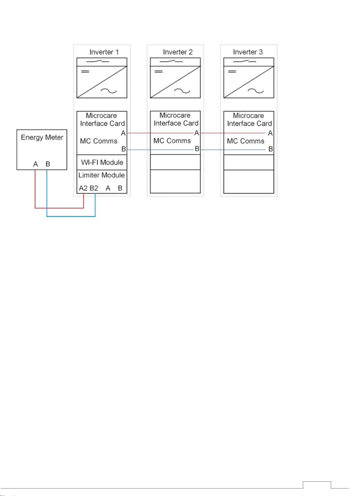
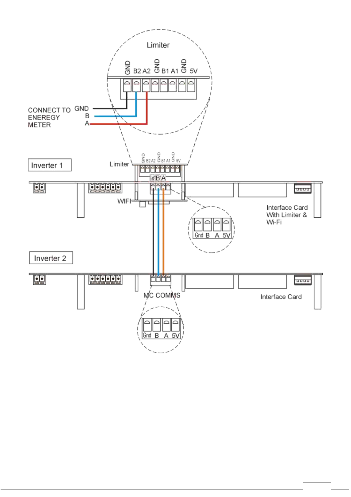
1.2 Basic Multiple Inverter Communivations Wiring Block Diagram
Each inverter is fitted with a Microcare interface card.
A Limiter module is only fitted to one Inverter.
The Limiter is programmed for the total installed Inverter Power.
The energy meter reads the load power and sets the limit for each inverter via the Limiter
module.
Communication between the inverters is established via the Microcare Interface Card MC
Comms Port.
Wi-Fi modules are required for logging purposes.

6
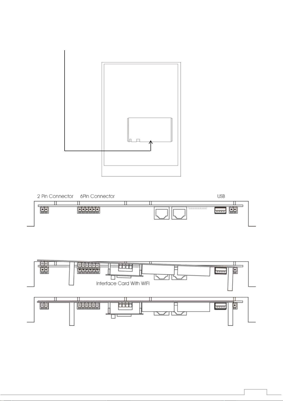
2. INTERFACE CARD OVERVIEW
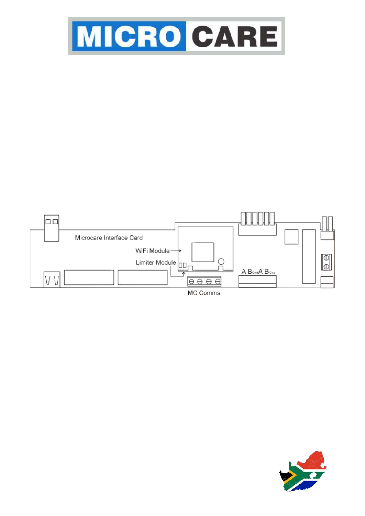
2.1 Microcare Interface Card Top View
2.2 Interface Card Assembly - Side View - BLUEPLANET 3TL1 –20TL3
2.3 Interface Card Assembly - Side View - BLUEPLANET 50
2.4 Interface Card Bottom View
2.5 Limter & WIFI Module Top View

7
3. ENERGY METER OVERVIEW
3.1 3ph Inline Energy Meter
3.2 3ph CT Energy meter
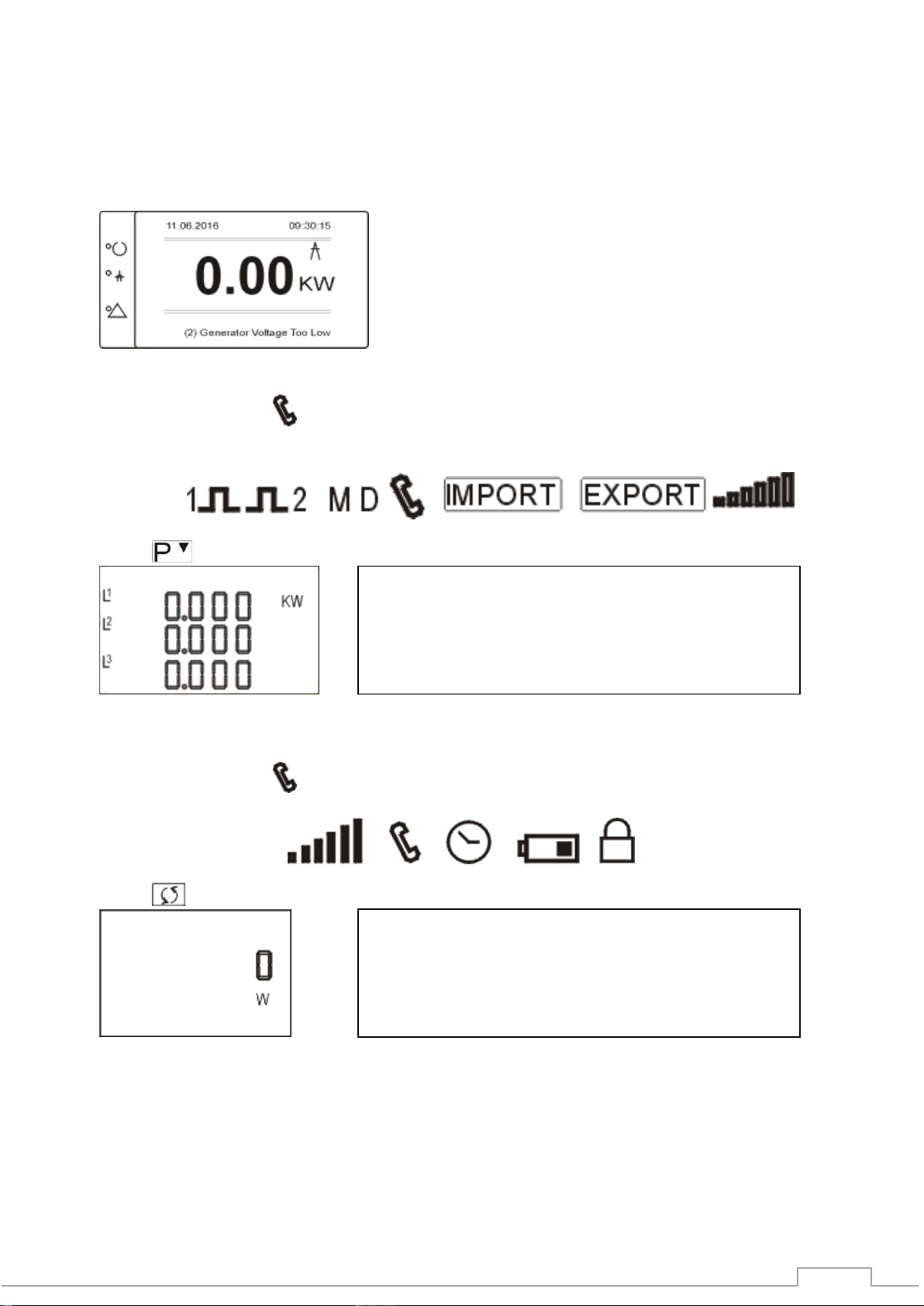
3.4 3ph Energy Meter Display Explanation
Selects the Voltage and Current display
screens
In Set-up Mode, this is the “Left” or “Back”
button
Select the Frequency and Power factor
display screens. In Set-up Mode, this is the
“Up” button
Select the Power display screens
In Set-up Mode, this is the “Down” button
Select the Energy display screens
In Set-up mode, this is the “Enter” or “Right”
button
1 2 3 4 5
1
Pulse Output 1 & 2
2
Max Demand Power or Current
3
Communication Indicator
4
Import, Export Information
5
Power, Bar Display
6
Total Value
7
Tariff Information
8
Low Battery Warning
9
10
Measurement Units
6
7
3
8
9
10
5
3.3 3 Ph Energy Meter Setup:
Energy Meters supplied by Microcare are factory
programmed for the following settings.
Set Address = 001
Set Baud Rate = 9.6k
Set Parity = None
Set Stop Bits = 1

8
3.5 Single Phase Energy Meter
3.6 Single Phase Energy Meter Display Explanation
2 3 4 5 6
9 10 11 12 13
Scroll Button - “Up and Down”
Enter Button
1
7 Digit Display
2
Total Value
3
4
Import, Export Information
5
MAX Demand, Power or Current
6
Pulse Output 1 & 2
7
Measurement Units
8
Pf=Power Factor Hz=Frequency
9
Bar Display Of Power
10
Communications Indicator
11
Time Indicator
12
Low Battery Warning
13
Lock Symbol
1
8
7
5
7
Single Phase Energy Meter Setup:
Energy Meters supplied by Microcare are factory
programmed for the following settings.
Set Address = 001
Set Baud Rate = 9.6k
Set Parity = None
Set Stop Bits = 1

9
4. BASIC WIRING DIAGRAMS
4.1 Basic Inline 1PH Energy Meter Wiring Diagram
10
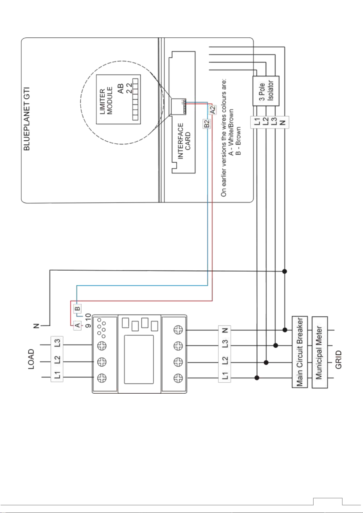
4.2 Basic Inline 3PH Enrgy Meter Wiring Diagram

11
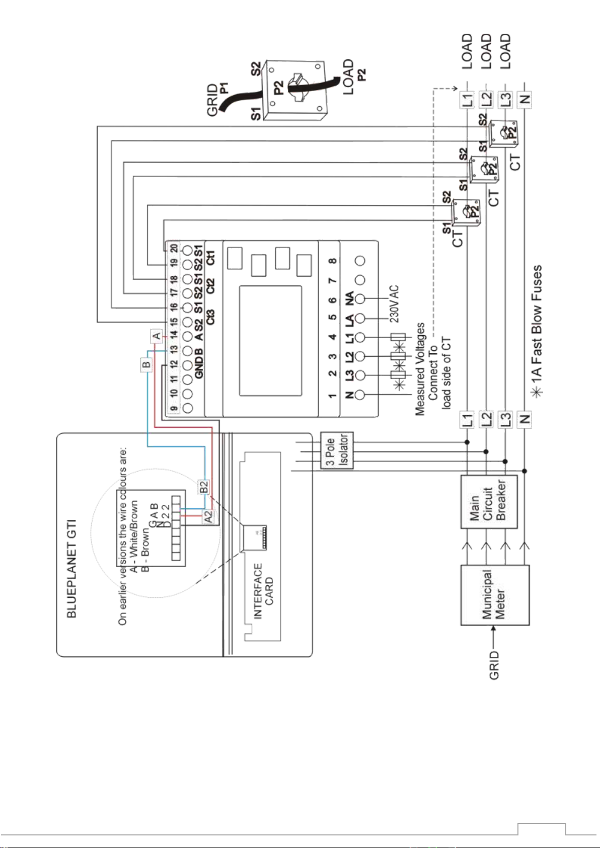
4.3 Basic CT 3PH Energy Meter Wiring Diagram Wiring
12

13
5. INTERFACE CARD INSTALLATION
5.1 BLUEPLANET 3TL1 –15TL3
Shut down the Kaco Grid Tied Inverter as per the Kaco manual before installing the Microcare
interface card or making any cable connections between devices.
Familiarise yourself with the layout of the Microcare Interface card, Limiter Card and the WIFI
module. Remove the bottom lid of the inverter. Locate the Kaco Interface card and slot the Microcare
interface card into the Kaco interface card. Ensure that the USB, 6 Pin and the 2 Pin connector seat
firmly into the mating sockets.
KACO and Microcare Interface Cards
…
A2 B2

14
5.2 BLUEPLANET 20TL3
Shut down the Kaco Grid Tied Inverter as per the Kaco manual before installing the Microcare
interface card or making any cable connections between devices.
Familiarise yourself with the layout of the Microcare Interface card, Limiter Card and the WIFI
module. Remove the bottom lid of the inverter. Install the ABS insulation plate. NB: This insulation
plate must be fitted. Locate the Kaco Interface card and slot the Microcare interface card into the
Kaco interface card. Ensure that the USB, 6 Pin and the 2 Pin connector seat firmly into the mating
sockets.
15
5.3 BLUEPLANET 50
Shut down the Kaco Grid Tied Inverter as per the Kaco manual before installing the Microcare
interface card or making any cable connections between devices.
The Kaco Interface card is located on the inside of the door panel.
Blueplanet 50 Interface Card
Position the Microcare interface card at a slight angle and seat the USB connection first, then push
the Microcare interface card downwards and seat the 2 pin and 6 pin sockets towards the mating
connectors till fully seated.
16
5.4 Comms Wiring 2 x Blueplanet 50 with Limiter

17
5.5 Comms Wiring 3 x Blueplanet 50 With Limiter
18
6. TESTING THE INSTALLED LIMITER AND ENERGY METER
Ensure that all the AC load circuit breakers are switched off.
DC diconnect switch in the OFF position.
Connect the grid supply to the inverter using the external AC circuit breaker/s.
Wait until the inverter starts-up and the start-up screen appears.
6.1 3 Ph Energy Meter
If the telephone Icon appears on the first line of the Energy Meter display,
it confirms that the Energy Meter is communicating with the inverter.
Press to Access the Energy Meter Power Menu screen. 0kW should display.
6.2 Single Phase Energy Meter
If the telephone Icon appears on the last line of the Energy Meter display,
it confirms that the Energy Meter is communicating with the inverter.
Press to Access the Energy Meter Active Power Menu screen. 0kW should display.
Please Note:
If the energy meter indicates a “-“ negative KW
reading, the CTS are connected the wrong way
round.
Please Note:
If the energy meter indicates a “-“ negative KW
reading, the CTS are connected the wrong way
round.

19
6.3 Grid Tied Limiter
From the inverter start-up screen
The start-up screen should display 0kW
Push - The main Menu Screen appears,
Push - The Measurement /Generator screen appears.
Push - The Measurements/Grid Menu appears,.
Push - The Power Control Menu Appears.
Start-up Screen Main Menu/Measurements Menu
Measuremenst/Generator Menu Measurements/Grid Menu
Measurements/Power Control Menu
Note that the Power Control % should now read “0%”.
Turn on the load circuit breakers and turn on a constant load.
For explanation purposes, if the installed inverter is a 5kW inverter an the load is 2kW.
2kw/5kw x 100 = 40%,
The inverter Power Control Menu should change from 0% to 40%.
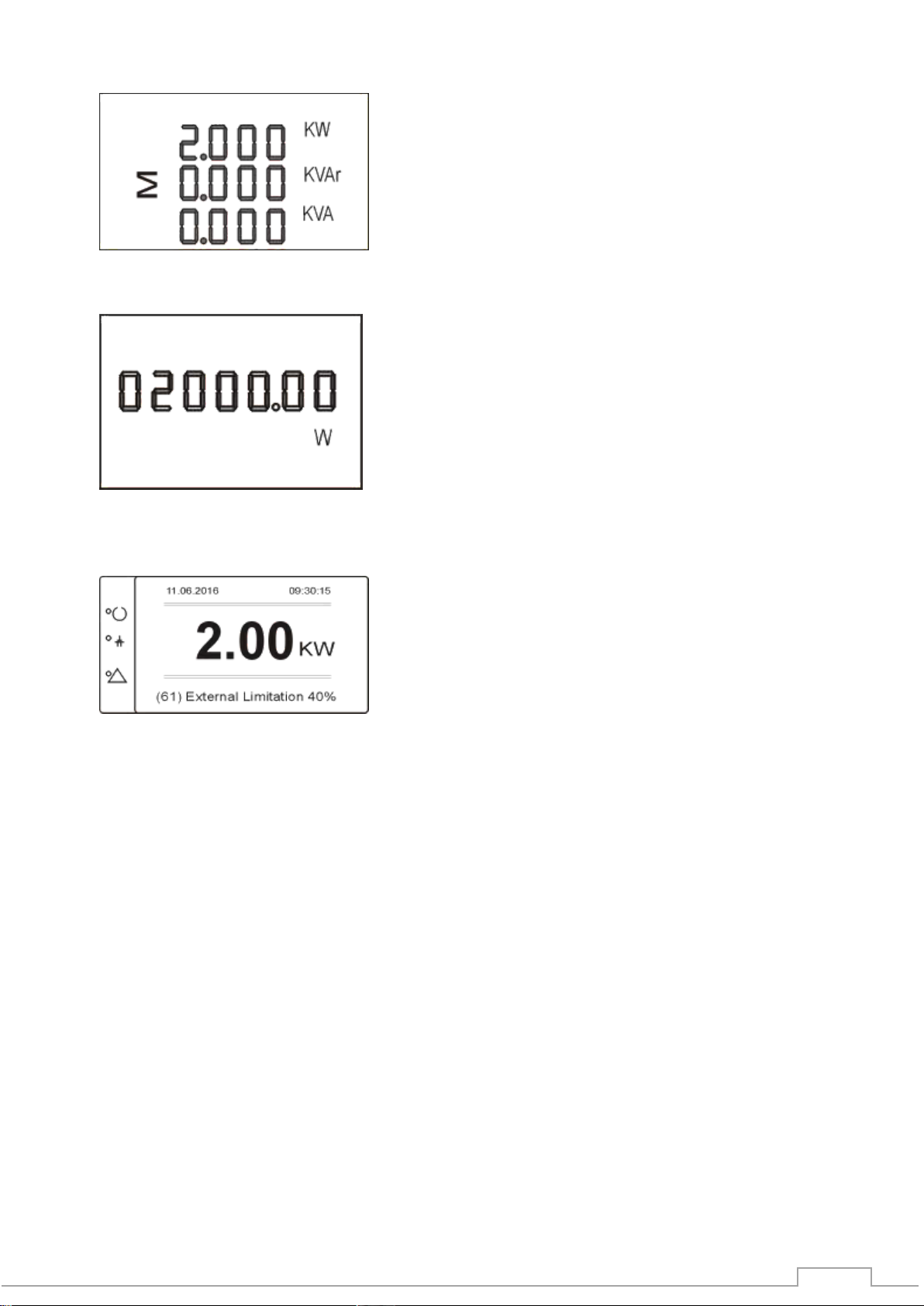
20
The 3PH Energy Meter should display 2kW
A single phase meter should dsiplay 2000W
Switch the inverter DC connect switch to the on position.
Wait until the Dc start up procedure is complete.
The Inverter should display the following information assuming a 2kW load.
Table of contents
Other Microcare Inverter manuals


