Microlight TX Series User manual

1
TX Series QR Code Scanners User
Manual
Beijing Microlight Internet Technology Co., Ltd.
June, 2017

1
Disclaimer
Before using the product, please read carefully all the contents of this TX Series Product User
Manual (hereinafter referred to as “Manual”) to ensure the safe and effective use of the product.
Do not disassemble the product or tear off the seal on the product. Otherwise, Beijing
Microlight Internet Technology Co., Ltd. will not be responsible for the warranty or
replacement of the product.
The pictures in this manual are for reference only. If there is a discrepancy between an
individual picture and the actual product, the actual product shall prevail. For the upgrade of
this product, Beijing Microlight Internet Technology Co., Ltd. reserves the right to modify the
document at any time without notice.
The use of this product is at your own risk. To the fullest extent permitted by applicable law,
damages and risks resulting from the use or inability to use the software, including but not
limited to direct or indirect personal damages, loss of commercial profits, trade interruption,
loss of business information or any other economic loss, Beijing Microlight Internet
Technology Co., Ltd. does not assume any responsibility.
All rights of interpretation and modification of this manual belong to Beijing Microlight
Internet Technology Co., Ltd.

2
Table of Contents
Disclaimer.........................................................................................................................................1
Copyright Notice...............................................................................................................................4
Preface...............................................................................................................................................5
Product Introduction......................................................................................................................... 5
Product Features................................................................................................................................5
Precautions.........................................................................................................................................6
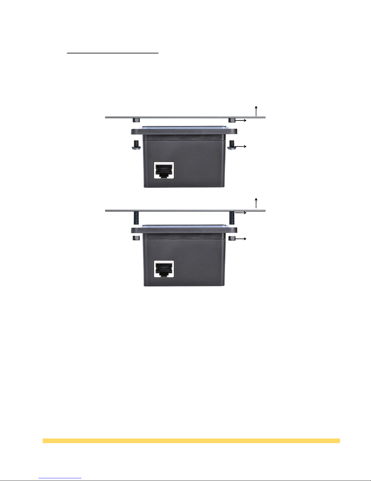
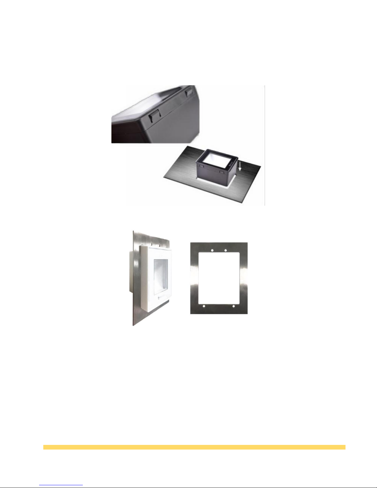
Installation and Disassemble .............................................................................................................7
TX200 Installation ..............................................................................................................................7
TX400 Installation...............................................................................................................................8
TX600 Installation ..............................................................................................................................8
TX800 Installation ..............................................................................................................................9
Chapter Ⅰ Product Parameters .....................................................................................................10
Appearance parameters.....................................................................................................................10
TX200 ................................................................................................................................................10
TX400 ................................................................................................................................................11
TX600 ................................................................................................................................................12
TX800 ................................................................................................................................................13
Size parameters ................................................................................................................................14
Reading parameters...........................................................................................................................14
Device parameters..............................................................................................................................15
Chapter Ⅱ Wiring instructions...........................................................................................................15
Pin definitions......................................................................................................................................15
USB interface.......................................................................................................................................16
Serial Port Wiring.................................................................................................................................16
TTL Wiring ..........................................................................................................................................17
Chapter III Product Configuration ....................................................................................................17
Run Configuration Tool .......................................................................................................................17
Configure Corresponding Functions ....................................................................................................18
Applied Configuration .......................................................................................................................21
USB Communication Setting ...............................................................................................................22
Serial port Communication Setting ......................................................................................................22
TTL Communication Setting ................................................................................................................23
Chapter IV Common Faults and Troubleshooting Methods .................................................................24

3
Chapter V Contact Information ........................................................................................................26

4
Copyright Notice
All information contained in this manual is protected by copyright, and
Beijing Microlight Internet Technology Co., Ltd. reserves all rights. Without
the written permission of our company, any unit or individual shall bear legal
liability for taking any form of excerpt, coping any or all of the contents of
this document or selling or using the product bundled with other products in
any way or for any reason.

5
Preface
Product Introduction
Thanks for using the TX series of scanners provided by Microlight Internet Ltd. This product can realize
QR code identification. Please read the user manual carefully before use, you will appreciate its perfect
function and simple operation method.
This product is mainly used for QR code identification. The company does not assume responsibility for the
property loss or personal injury caused by the user ’s abnormal operation. Please design and develop the
corresponding product according to the technical specifications and reference in the manual. Also please
pay attention to the general safety matters that should be taken into account when using mobile products.
Before the statement, the company has the right to modify the contents of this manual according to the
needs of technological development.
Product Features
Strong reading ability
It can recognize the QR code and one-dimensional code on the screen of the mobile phone, support the
enhanced engine mode, and can scan and read the code when the screen of the mobile phone is dark.
Paper code reading ability
The main QR codes and various one-dimensional codes printed on the paper can also be read.
High speed reading
Different mobile phone LCD screens generally have different contrast, color, and degree of reflection,
which can be read as long as the code system is within the reading window.
Easy to use
Scanners can be configured using configuration tools to achieve optimal operation.

6
Precautions
Dismantling and modification: Please do not disassemble or modify the hardware of the
product. If the equipment is damaged thereof, the company will not be responsible for
the warranty.
Abnormal condition: Keep away from fire. If you find unusual odor, overheat or smoke,
please immediately turn off the power switch and unplug the plug from the AC outlet,
and contact the dealer where you purchased the product or our customer service center.
Drop damage: If the product is damaged due to falling on the ground, please
immediately turn off the power and contact the dealer where you purchased the product
or our customer service center.
Placement location: Please do not place the product in an unstable or uneven place, so as
to avoid the device falling down and causing damage; please do not put the device in a
place with large amount of moisture or dust, so as to avoid causing electric leakage or
fire.
Please keep the illuminating glass lens clean. When wiping, use soft cotton or lens paper.
Do not wipe the window glass with detergent or dissolved liquid.
Do not touch the window glass with abrasive substances, so as to avoid wearing the
window glass and affecting the reading effect.

7
Installation and Disassemble
TX200 Installation
Installation instructions 1
Nut column diameter does not exceed 5.8mm, through the scanner to fix the round hole outside
diameter.
The diameter of the screw part of the fixing screw is not more than 4mm, tighten the nut from the
back through the hole inside diameter
When the plate thickness is 2mm, the maximum nut height is 3.5mm
When the plate thickness is 1.5mm, the maximum height of the welded nut on the steel plate is 4mm
Installation instructions 2:
Screw column diameter not more than 4mm is okay, directly through the scanner to fix the round hole
internal diameter
Chassis
Nut column
Fixing screw
Installation instructions 1
Installation instructions 2
Chassis
Nut column
Fixing screw

8
TX400 Installation
TX600 Installation
Inside insert, perfect replacement vending machine bill validator
Buckle design
Recommended opening size: 67.5*88mm
Outside embedding
1 second installation

9
TX800 Installation
Desktop, ready to use

10
Chapter Ⅰ Product Parameters
Appearance parameters
TX200
Picture 1-1

11
TX400

12
TX600

13
TX800
Top view
Side view
Overall product view

14
Size parameters
Table 1-1 Appearance parameters
Parameter
Type
TX200
TX400
TX600
TX800
physical
dimension
95*84*48mm
95*70*48mm
134*92*50mm
88*67*48mm
Reading
window size
59*46mm
59*46mm
59*46mm
59*46mm
Installation
method
Embedded
installation
External
installation
Embedded
installation
Materials
ABS
ABS
ABS
ABS
Hole Size
67.5*88mm
Corner radius
4.27mm
67.5*88mm
Corner radius
4.27mm
108.2*86.2m
m, Corner
radius 2.1mm
Reading parameters
Table 1-2 Reading parameters
TX series QR Code Reading parameters
Image Sensor
300,000 pixel CMOS (640*480)
light source
Led diffuse lighting (white lighting, red indicator)
Instruction
Buzzer, three blue LED status indicators, red LED indication
Identification code
QR Code, Data Matrix, EAN_13, EAN_8, RSS_14, CODE_39,
CODE_93, CODE_128, ITF, Code Bar, Inverse Code, Mirror
Code, etc.
Print contrast
≥25%
Reading accuracy
≥7mil
Reading speed
70ms/times
Field of view angle
Horizontal field of view 77°, vertical field of view 60°
Reading angle
Tilt ±40°, deflection ±30°, rotate 360°
Depth of field
0mm~55mm(15mil QR Code)

15
Device parameters
Table 1-3 Specific parameters
Technical indicators
Specific parameters
Microprocessor
32-bit 1G CPU, high-speed DDR memory
Data interface
RS232 (9.6 ~ 115.2kbps), USB1.1 (HID-KBW,
HID-POS), custom HID (add USB development
interface, high-speed transmission)
Data line
RS232 data line (USB power supply interface + DB9 data
interface), USB cable, TTL line
Operating temperature
-20~70 degrees Celsius
Storage temperature
-40 to 80 degrees Celsius
Humidity
Relative humidity 0%~95%
Ambient light intensity
0~80,000LUX
Operating Voltage
Supports 5~15V wide voltage input
Working current
0.15A (5V) or 0.05A (15v)
Maximum power
Consumption
0.75W
International Certification
FCC Part15 Class B,CE EMC Class
Maintenance Requirements
Support remote maintenance and online upgrade
Materials
Body: Imported PC window: Tempered glass
Operating System
Supports Windows (xp.7.8.10), Linux, Android, Mac, etc.
Chapter Ⅱ Wiring instructions
Pin definitions

16
Table 2-1
TX200 external output interface is RJ45 crystal head, pin definition is as follows:
Table 2-2 wire sequence table
USB interface
The usage steps are as follows:
1. First connect the RJ45 plug of the data line with the scanner;
2. Connect the USB port on the other end of the cable to the PC (or control board).
Table 2-3 USB wiring
Serial Port Wiring
The usage steps are as follows:
1, first connect the RJ45 plug on the data line with the scanner;
2. Connect the RS232 interface on the data cable to the PC (or control board).
3. Then connect the USB port of the data cable to the 5V power supply, which can be the USB
port on the computer, or other USB ports that can provide 5V power supply;
4. After the power is turned on, the auxiliary lighting of the product will be turned on. After
hearing the “buzz”sound, the scanner will enter the working state.
PIN#
Signal Name
I/O
Description
1
NC
NC
2
NC
NC
3
GND
-
Power ground
4
VCC
-
Power input
5
TX-232
Output
Serial 232 level output
6
RX-232
Input
Serial 232 level input
7
UART1_TXD_TTL
Output
TTLinterface XMIT
8
UART1_RXD_TTL
Input
TTLinterface RxDn

17
Table 2-4 RS232 wiring
TTL Wiring
TTL interface
Please connect according to the TTL line sequence.
Table 2-5 TTL wiring
Chapter III Product Configuration
Run Configuration Tool
(1) Double-click the TX configuration tool application.
Table 3-1 Configuration tool icon

18
Table 3-2 Configuration tool interface
(2) Device Connection: Click the [Connect Device] button and the message "Device Connection
Successful" appears.
Configure Corresponding Functions
(1)Working Mode: Can be configured as normal mode or development mode, under normal mode,
Adjustable to USB, TTL, Serial port 232/485, WiFi four output methods.
Table 3-3 Ordinary mode
Under development mode, can be configured as USB, serial protocol, communication protocols
methods etc. choose according to your needs.

19
Table 3-4 Development mode
(2)General configuration:
Table 3-5 General configuration options
* Configuration password: The default is 1234567887654321. If you do not enter a password, you
cannot configure it.
* Code selection: Changing the code system is available, the QR code (QR code) is checked by
default. The rest of the code system can be selected according to your needs.
* Output settings: Scan code prefix and suffix can be set;
* Decoding Engine: Choosing to QR strengthens or bar code strengthens , choose according to
your needs.
This manual suits for next models
4
Table of contents