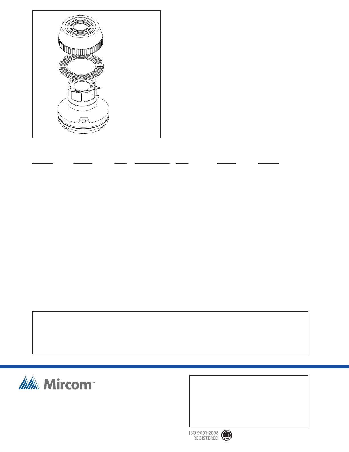
manuals.online logo
Brands
  1. Home
  2. •
  3. Brands
  4. •
  5. Microm
  6. •
  7. Smoke Alarm
  8. •
  9. Microm 1451B-A User manual

Microm 1451B-A User manual

2 & 4 WIRE IONIZATION SMOKE DETECTOR 1451B-A
Description
The Mircom 1451B-A ionization smoke detectors
respond quickly to both fast flaming and slow
smouldering fires are required by UL268. Unipolar
dual chamber sensor has the sensitivity needed to
quickly detect smoke, and the stability needed to
avoid false alarms.
Features
Unique dual unipolar sensor• Provides exceptional stability• Factory preset at 1.9% nominal sensitivity• Stable operation up to 1,200 feet per minute (6• meters per second) air velocities
Removable cover for field cleaning• Two visible LED “blink” in standby• Sealed against dirt, insects and back pressure• 3 year Limited Warranty• Field adjustable sensitivity• Field metering of detector sensitivity• Built-in test switch• Low standby current• Built-in tamper-resistant feature• Designed for direct surface or electrical box• mounting
360°fieldviewingangleofthevisualalarmLEDs• Insect-resistant screening (0.020”/0.508mm• openings)
Easy plug-in of the head to base• SEMS screws for easy wiring• Optional recess mounting•
Mircom reserves the right to make changes at any time without notice in prices, colours, materials, components, equipment, specifications and models and also to discontinue models.
Installation
Maximum number of detectors per zone is listed in
the installation manual for each control panel. Easy
to install and maintain, this detector is designed
for direct surface mounting (using one of the B400
Series bases listed below). Easy-to-wire screw
terminalsallowfastandsimplefieldwiringofIN,OUT
and remote annunciator connections.
Consult Mircom control panel specifications for the
maximumallowableloopresistancefortheparticular
control panel to be used.
To prevent wiring mistakes, observe polarities and
make certain that each conductor is identifiable. A
copy of Installation and Maintenance Instructions is
packagedwith eachdetector. Forfurtherinformation,
refer to NFPA 72E “Standard on Automatic Fire
Detectors.”
Application
Use for protection of life and property. Superior
to photoelectric detectors in detecting fast flaming
fires. Superior to bipolar detectors in avoiding false
flames.
5105
NOT TO BE USED FOR INSTALLATION PURPOSES.
MEA
approved
APPROVED
CATALOG NUMBER
REMOVABLE COVER
FOR CLEANING
REMOVABLE SCREEN
(P/N RS14)
LOCK PRONG
SENSING CHAMBER
Canada
25 Interchange Way
Vaughan, Ontario L4K 5W3
Telephone: (905) 660-4655
Fax: (905) 660-4113
Web page: http://www.mircom.com Email: [email protected]
Distributed by:
CAT. 5105
Rev. 5
Architects/Engineer Specifications
Operating Voltage: Mounting Base Dependent
Standby Current: 120 micro amps
Sensitivity: 1.9% nominal
Weight: 0.5 pounds (277 grams)
Size: 2.4”/6 mm high
4.0”103 mm diameter
(6.2”/158 mm diameter with
flanged bases).
1451 Ionization detector. Must be mounted to one of the B400 Series Bases listed.
RA-400Z Remote annunciator for 2 or 4 wire applications. Use with any System Sensor 400 series plug-in
detector. Fits standard single-gang electrical box.
MOD400R Field test module for all of the System Sensor 400 Series Smoke Detectors.
General Specifications
Ordering Information
All 1451B-A ionization smoke detectors contain a
uniquedualsource,dualunipolarchamberdetection
design which will sense the presence of smoke
particlesproduced byfastcombustionas wellasslow
smouldering fires. Additional key features include
a blinking LED standby status indicator, an easily
visible alarm indication and provision for convenient
field test and metering
The back of the detector is sealed to block back
pressureairflow. Thechamber is protectedbyafine
mesh(0.20”/0.508mm)screentominimizeproblems
with dust, dirt and insects. If cleaning is required, it
is easy to remove the cover (with a special tool) and
obtainaccess to the screen andchamber to perform
a thorough cleaning.
Base Model Loop Current Contact Standby Current Draw
Number Version Type Limit Resistor Type Voltage or Alarm
B401B-A UL & ULC 2-wire No - 8.5 to 35 VDC 10 to 100 mA*
B406B-A UL & ULC 2-wire No Form C 15 to 35 VDC 12 to 100*
* Limited by control panel
Relay Contact Ratings on the B406B base: Resistive or Inductive (60% power factor) load.
Form A: 2.0 amps @ 30 VAC/DC
Form C: 0.6 amps @ 110 VAC, 2.0 amps @ 30 VDC.
1.0 amps @ 125 VAC, 2.0 amps @ 30 VAC.
Construction: Flame retardant
white Noryl7plastic
Temperature: 32°to 120°F
(0 to 49°C)
Humidity Range: 10 to 93% R.H.
(non-condensing)
Maximum air 1,200 feet per minute
velocity: (6 meters per second)
NOT TO BE USED FOR INSTALLATION PURPOSES.
U.S.A.
4575 Witmer Industrial Estates
Niagara Falls, NY 14305
Toll Free: (888) 660-4655
Fax Toll Free: (888) 660-4113

Popular Smoke Alarm manuals by other brands

LST AO-58000-600 Specification sheet

LST

LST AO-58000-600 Specification sheet

First Alert SMOKE & CO COMBO ALARM SC05B Specification sheet

First Alert

First Alert SMOKE & CO COMBO ALARM SC05B Specification sheet

Red Smoke Alarms R10RF installation instructions

Red Smoke Alarms

Red Smoke Alarms R10RF installation instructions

RadioLink Ei168 user manual

RadioLink

RadioLink Ei168 user manual

EMC FC-610-001 installation guide

EMC

EMC FC-610-001 installation guide

vds GS508 user manual

vds

vds GS508 user manual

Hochiki SLV Series installation instructions

Hochiki

Hochiki SLV Series installation instructions

techem smoke detector 2 operating instructions

techem

techem smoke detector 2 operating instructions

AROHA SM11R4 Quick reference guide

AROHA

AROHA SM11R4 Quick reference guide

Almaks STD-200-CA1 installation manual

Almaks

Almaks STD-200-CA1 installation manual

Bosch D296 Series installation manual

Bosch

Bosch D296 Series installation manual

Panasonic EBL512 Specification sheet

Panasonic

Panasonic EBL512 Specification sheet

Nexa EL1313/KD-101LC user manual

Nexa

Nexa EL1313/KD-101LC user manual

COP-USA SDDVR-WF user guide

COP-USA

COP-USA SDDVR-WF user guide

System Sensor B210LP Installation and maintenance instructions

System Sensor

System Sensor B210LP Installation and maintenance instructions

First Alert SA150B user manual

First Alert

First Alert SA150B user manual

Ei Electronics Ei 169 Instruction leaflet

Ei Electronics

Ei Electronics Ei 169 Instruction leaflet

usi USI-1213 manual

usi

usi USI-1213 manual

manuals.online logo
manuals.online logoBrands
  • About & Mission
  • Contact us
  • Privacy Policy
  • Terms and Conditions

Copyright 2025 Manuals.Online. All Rights Reserved.