MicroMic C 417III User manual

C417
III
BEDIENUNGSHINWEISE . . . . . . . . . . . . . S. 2
Bitte vor Inbetriebnahme des Gerätes lesen!
USER INSTRUCTIONS . . . . . . . . . . . . . . . p. 13
Please read the manual before using the equipment!
MODE D’EMPLOI . . . . . . . . . . . . . . . . . . . . . . p. 24
Veuillez lire cette notice avant d’utiliser le système!
ISTRUZIONI PER L’USO . . . . . . . . . . . . . p. 35
Prima di utilizzare l’apparecchio, leggere il manuale!
MODO DE EMPLEO . . . . . . . . . . . . . . . . . . . p. 46
Antes de utilizar el equipo, sirvase leer el manual!
INSTRUÇÕES DE USO . . . . . . . . . . . . . . . p. 57
Favor leia este manual antes de usar o equipamento!

2
1.1 Sicherheits-
hinweis
1.2
Lieferumfang
1.3 Empfohlenes
Zubehör
1.4 Besondere
Merkmale
Überprüfen Sie bitte, ob das Gerät, an das Sie das
Mikrofon anschließen möchten, den gültigen Si-
cherheitsbestimmungen entspricht und mit einer
Sicherheitserdung versehen ist.
Kontrollieren Sie bitte, ob die Verpackung alle
oben angeführten Teile enthält. Falls etwas fehlt,
wenden Sie sich bitte an Ihren AKG-Händler.
• Professionelles Miniatur-Ansteckmikrofon.
• Kondensatorwandler mit kugelförmiger Richt-
charakteristik für natürlichen Klang.
• Weiter Übertragungsbereich für Sprache, Ge-
sang, Violine.
1 Sicherheitshinweis/Beschreibung
1 C 417III 1 W 407 1 H 40/1 1 H 41
• Mikrofonkabel MK 9/10: 10 m 2-polig
geschirmtes Kabel mit XLR-Stecker
und XLR-Kupplung
• Phantomspeiseadapter MPA III L
• Batteriespeisegeräte
B 29 L, B 15
• Phantomspeise-
geräte N 62 E,
N 66 E, B 18
4

3
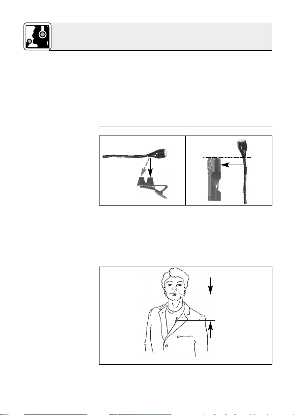
• Geeignet zur Befestigung an der Kleidung oder
direkt am Kopf der Anwenderin/des Anwen-
ders.
Das C 417III ist ein professionelles Miniatur-Kon-
densator-Ansteckmikrofon mit kugelförmiger
Richtcharakteristik. Auf Grund des weiten Über-
tragungsbereichs von 20 bis 20.000 Hz, der gerin-
gen Verzerrungen bei hohem Schalldruck sowie
der kleinen Abmessungen und des universell an-
wendbaren Zubehörs eignet sich das Mikrofon
ideal für alle Anwendungen, wo unauffällige Mi-
krofontechnik und große Bewegungsfreiheit der
Anwenderin/des Anwenders gefordert werden.
Zwei verschiedene Farbvarianten ermöglichen die
fast unsichtbare Integration des Mikrofons in die
Maske von SchauspielerInnen und SängerInnen.
Ein externer Windschutz für die Dämpfung von
Windgeräuschen bei Einsatz im Freien ist im Lie-
ferumfang enthalten.
Das C 417III ist in drei Ausführungen erhältlich:
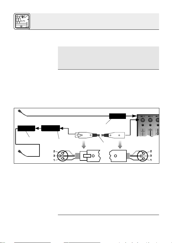
• Mit 3-poligem XLR-Stecker mit eingebautem
Adapter für Universal-Phantomspeisung von 9
bis 52 V.
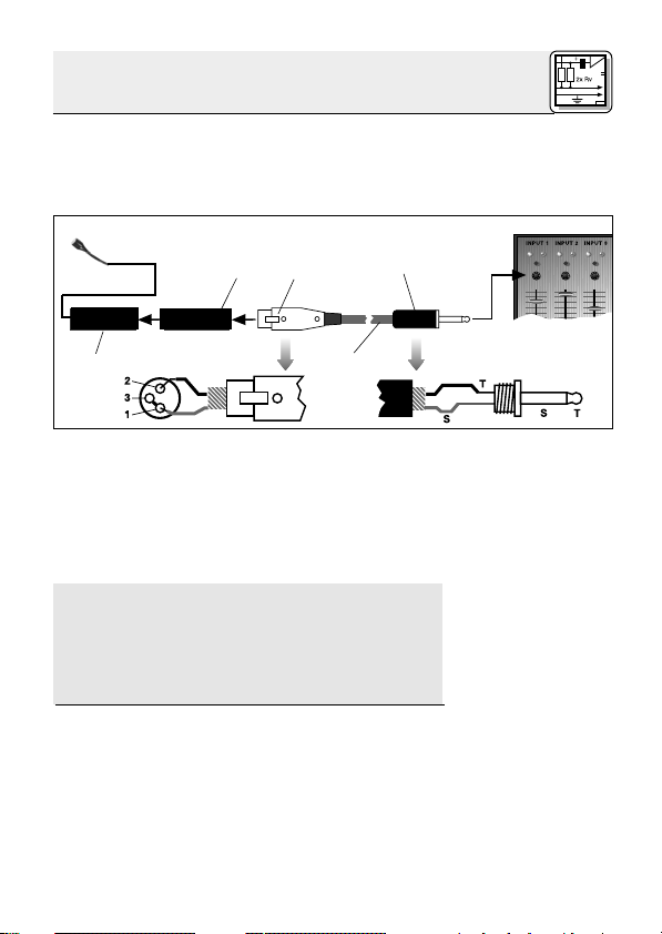
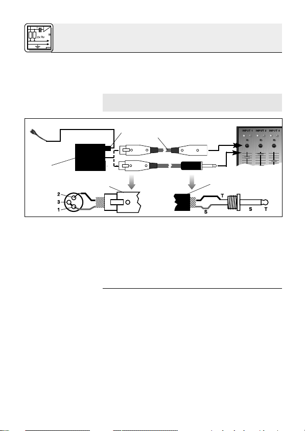
• Mit verriegelbarem Mini-XLR-Stecker zum An-
schluss an Batteriespeisegerät B 29 L, Phan-
tomspeiseadapter MPA III L oder AKG-
Taschensender.
• Wie C 417III L, Kabel und Mikrofonkopf pink.
1 Beschreibung
1.5 Kurz-
beschreibung
1.6 Varianten
C 417III PP
C 417III L
C 417III PL
4

4
2.1 Einleitung
Wichtig!
2.2 C 417III PP
2.2.1 Anschluss
an symmetri-
sche Eingänge
Siehe Abb. 1.
Das C 417III PP ist ein Kondensatormikrofon und
benötigt daher eine Stromversorgung.
Wenn Sie andere als die von AKG empfoh-
lenen Speisegeräte verwenden, kann das
Mikrofon beschädigt werden und erlischt
die Garantie.
1. Stecken Sie den Phantomspeiseadapter (1) am
Mikrofonkabel an einen symmetrischen XLR-
Mikrofoneingang mit Phantomspeisung an.
2. Schalten Sie die Phantomspeisung ein. (Lesen
Sie dazu in der Betriebsanleitung des jeweili-
gen Gerätes nach.)
3. Wenn Ihr Mischpult keine Phantom-
speisung besitzt, stecken Sie den
Phantomspeiseadapter (1) an ein optionales
AKG-Phantomspeisegerät (2) (N 62 E, N 66 E,
B 18, B 15) an und verbinden Sie das
Phantomspeisegerät mit Hilfe eines XLR-
Kabels (3) (z.B. AKG MK 9/10 - nicht mitgelie-
fert) mit einem symmetrischen Eingang.
2 Anschluss
XLR
1
2
1
3
Phantom
XLR
Abb. 1: Anschluss an symmetrischen Eingang
4

5
2.2.2 Anschluss
an asymmetri-
sche Eingänge
Siehe Abb. 2.
Hinweis:
2.3 C 417III L/PL
2.3.1 Anschluss
mittels B 29 L
Siehe Abb.3.
Kabel anstecken:
Phantomspeisegeräte (2) von AKG können Sie auch
an einen asymmetrischen Eingang anschließen.
Verwenden Sie dazu ein Kabel (3) mit XLR-
Stecker (weiblich) und Mono-Klinkenstecker:
1. Verbinden Sie im XLR-Stecker (4) mittels einer
Drahtbrücke Stift 1 mit Stift 3 und mit der
Abschirmung.
2. Verbinden Sie die innere Ader des Kabels mit
Stift 2 des XLR-Steckers (4) und der Spitze
des Klinkensteckers (5).
Beachten Sie, dass asymmetrische Kabel Ein-
streuungen aus Magnetfeldern (von Netz- und
Lichtkabeln, Elektromotoren usw.) wie eine An-
tenne aufnehmen können . Bei Kabeln, die län-
ger als 5 m sind, kann dies zu Brumm- und
ähnlichen Störgeräuschen führen.
Mit dem optionalen Batteriespeisegerät B 29 L
können Sie das Mikrofon an symmetrische oder
asymmetrische Eingänge ohne Phantomspeisung
anschliessen.
1. Stecken Sie den Mini-XLR-Stecker (1) am
Mikrofonkabel bis zum Anschlag in eine der
beiden Mini-XLR-Buchsen am B 29 L (2).
Der Stecker (1) verriegelt sich automatisch.
2 Anschluss
XLR Phantom
1
2
3
45
Abb. 2: Anschluss an asymmetrischen Eingang
4

6
Kabel abziehen:
Wichtig!
Siehe Abb. 3.
Symmetrischer
Eingang:
Asymmetrischer
Eingang:
2.3.2 Anschluss
mittels MPA III L
Siehe Abb. 4.
Kabel abziehen:
Zum Abziehen des Kabels drücken Sie auf
den Entriegelungsknopf am Mini XLR-Stecker
(1) und ziehen Sie den Stecker (1) aus der
Buchse heraus.
Um das Kabel nicht zu beschädigen, zie-
hen Sie niemals am Kabel selbst!
2. Verbinden Sie das B 29 L (2) mit dem
gewünschten Eingang.
• Zum Anschluss an einen symmetrischen
Eingang verwenden Sie ein handelsübli-
ches XLR-Kabel (3).
• Siehe Kapitel 2.2.2.
1. Stecken Sie den Mini-XLR-Stecker (1) am
Mikrofonkabel bis zum Anschlag in die Mini-
XLR-Kupplung (2) am Anschlusskabel des
MPA III L (3).
Der Stecker (1) verriegelt sich automatisch.
Siehe Kapitel 2.3.1.
2. Stecken Sie den MPA III L (3) an einen sym-
metrischen XLR-Mikrofoneingang mit Phan-
tomspeisung an.
3. Schalten Sie die Phantomspeisung ein. (Lesen
Sie dazu in der Betriebsanleitung des jeweili-
gen Gerätes nach.)
2 Anschluss
B 29 L
1
2
3
45
Abb. 3: Anschluss-Schema mit B 29 L
4

7
Siehe Abb. 4.
2.3.3 Anschluss an
Taschensender
4. Wenn Ihr Mischpult keine Phantom-
speisung besitzt, stecken Sie den MPA III L
(3) an ein optionales AKG-Phantomspeise-
gerät (4) (N 62 E, N 66 E, B 18, B 15) an und
verbinden Sie das Phantomspeisegerät (4) mit
Hilfe eines XLR-Kabels (5) (z.B. AKG MK 9/10
- nicht mitgeliefert) mit einem symmetrischen
Eingang.
Lesen Sie in der Bedienungsanleitung Ihres
Taschensenders nach.
2 Anschluss
Mini XLR Mini XLR MPA
MPA
3
Phantom
4
123
5
Abb. 4: Anschluss-Schema mit MPA III L
4

8
3.1 Einleitung
3.2 Anwendung
als Lavalier-
mikrofon
Abb. 5: Mikrofon
an Ansteckclip (a)
und Anstecknadel
(b) befestigen
Abb. 6: Mikrofon
nahe beim Mund
befestigen
Der große Vorteil eines an der Kleidung oder in der
Maske befestigten Mikrofons besteht darin, dass
der Abstand zwischen dem Mikrofon und dem
Mund der Anwenderin/des Anwenders unabhän-
gig von deren/dessen Bewegungen immer gleich
bleibt und damit keine Pegelschwankungen zu
befürchten sind. Die Bewegungsfreiheit bleibt er-
halten, die Hände bleiben frei.
1. Klemmen Sie das Kabel unmittelbar hinter dem
Mikrofongehäuse in eine der Aufnahmerillen
des mitgelieferten Ansteckclips H 40/1 (Abb.
5a) bzw. der mitgelieferten Anstecknadel H 41
(Abb. 5b).
2. Befestigen Sie das Mikrofon so nahe wie mög-
lich beim Mund der Rednerin/des Redners an
3 Anwendung
a b
min.
4

9
Hinweis:
3.3 Anwendung
als Aufnahme-
oder
Stützmikrofon
3.4 Theater,
Musical, Oper
Abb. 7: Mikrofon in
der Maske
integriert
der Kleidung, z.B. am Revers.
Je geringer der Abstand zwischen dem Mikro-
fon und der Schallquelle, umso geringer ist die
Gefahr akustischer Rückkopplungen.
1. Klemmen Sie das Kabel unmittelbar hinter dem
Mikrofongehäuse in die entsprechende Auf-
nahme des mitgelieferten Ansteckclips H 40/1
(Abb. 5a) bzw. der mitgelieferten Anstecknadel
H 41 (Abb. 5b).
2. Befestigen Sie das Mikrofon an einem geeig-
neten Dekorationsteil (z.B. Kulisse, Hinter-
grund, Vorhang o.ä.).
Befestigen Sie das Mikrofon in der Maske mög-
lichst nahe beim Mund.
Abb. 7 zeigt eine Möglichkeit der Positionierung.
Je nach den Erfordernissen der Inszenierung kön-
nen Sie das Mikrofon z.B. auch an der Stirn an-
bringen.
3 Anwendung
4

10
3.5 Violine
Abb. 8: Abnahme
der Violine
Siehe Abb. 8. Falls das Mikrofon nicht an der Violine selbst befe-
stigt werden kann oder darf, können Sie das Mi-
krofon mit Mastix an der Wange der Geigerin/
des Geigers befestigen.
Diese Methode hat folgende Vorteile:
• Das Mikrofon ist nicht an der Violine selbst be-
festigt, daher wird der Klang der Violine nicht
beeinflusst.
• Es besteht keine Gefahr, die Violine durch Kle-
beband o.ä. zu beschädigen.
• Die Violine benötigt keinerlei lästige Kabelver-
bindung.
Reinigen Sie das Gehäuse des Mikrofons mit ei-
nem mit Wasser befeuchteten Tuch.
3 Anwendung
4 Reinigung
4

11
5 Fehlerbehebung
Fehler
Kein Ton:
Verzerrungen:
Mögliche Ursache
1. Mischpult und/oder
Verstärker ausge-
schaltet.
2. Kanal-Fader oder
Summenpegelregler
am Mischpult oder
Lautstärkeregler des
Verstärkers steht auf
Null.
3. Mikrofon nicht an
Mischpult oder
Verstärker ange-
schlossen.
4. Kabelstecker nicht
richtig angesteckt.
5. Kabel defekt.
6. Keine Speise-
spannung.
1. Gain-Regler am
Mischpult zu weit
aufgedreht.
2. Mischpulteingang zu
empfindlich.
Abhilfe
1. Mischpult und/oder
Verstärker ein-
schalten.
2. Kanal-Fader oder
Summenpegelregler
am Mischpult oder
Lautstärkeregler des
Verstärkers auf ge-
wünschten Pegel
einstellen.
3. Mikrofon an Misch-
pult oder Verstärker
anschließen.
4. Kabelstecker
nochmals an-
stecken.
5. Kabel überprüfen
und falls nötig er-
setzen.
6. Phantomspeisung
einschalten.
Phantomspeise-
gerät: ans Netz
anschließen bzw.
Batterie(n) einlegen.
Kabel überprüfen
und falls nötig er-
setzen.
1. Gain-Regler zurück-
drehen.
2. 10-dB-Vorab-
schwächung
zwischen Mikrofon-
kabel und Eingang
stecken.
4

12
6 Technische Daten
Arbeitsweise: Kondensatormikrofon mit
Permanentladung
Richtcharakteristik: Kugel
Übertragungsbereich: 20 - 20.000 Hz
Empfindlichkeit: 10 mV/Pa (-40 dBV bez. auf 1 V/Pa)
Elektrische Impedanz bei 1000 Hz: 200
Empfohlene Lastimpedanz: 2000
Grenzschalldruckpegel für 1% / 3% Klirrfaktor: 118 / 126 dB SPL
Äquivalentschalldruckpegel: 34 dB (nach IEC 60268-4)
Speisespannung: C 417III PP: 9-52 V Universalphantomspeisung
C 417III L/PL:
Batteriespeisegerät B 29 L,
Phantomspeiseadapter
MPA III L
oder AKG WMS Taschensender
Stromaufnahme: ca. 2,2 mA
Kabellänge/Steckerart: C 417III PP: 3 m / XLR 3-polig
C 417III L/PL: 1,5 m / Mini-XLR 3-polig
Oberfläche: mattschwarz (PP, L) oder pink (PL)
Abmessungen: 7,5 Ø x 15 mm
Gewicht netto (ohne Kabel)/brutto: C 417III PP: 8 g / 220 g
C 417III L/PL: 8 g / 160 g
Dieses Produkt entspricht den in der Konformitätserklärung angegebenen
Normen. Sie können die Konformitätserklärung auf http://www.akg.com oder
Frequenzgang Polardiagramm
4

13
Please make sure that the piece of equipment
your microphone will be connected to fulfills the
safety regulations in force in your country and is
fitted with a ground lead.
Check that the packaging contains all of the com-
ponents listed above. Should anything be miss-
ing, please contact your AKG dealer.
• Professional miniature clip-on microphone.
• Omnidirectional condenser transducer for nat-
ural sound.
• Extended frequency response for clear repro-
duction of speech, vocals, violin.
1 Precaution/Description
1.1 Precaution
1.2 Unpacking
1.3 Optional
Accessories
1.4 Features
1 C 417III 1 W 407 1 H 40/1 1 H 41
• MK 9/10 microphone cable: 10-m
(30-ft.) 2-conductor shielded cable
w/male and female XLR connectors
• MPA III L phantom power adapter
• B 29 L, B 15 battery power
supplies
• N 62 E, N 66 E,
B 18 phantom
power suppplies
4

14
1.5 Brief
Description
1.6 Versions
C 417III PP:
C 417III L:
C 417III PL:
• Fastens on clothing or directly on the user's
head.
The C 417III is a professional miniature condenser
clip-on microphone with an omnidirectional polar
pattern. With its wide frequency range extending
from 20 Hz to 20 kHz, low distortion at high sound
pressure levels, small size, and useful accesso-
ries, the C 417III is an ideal choice for use in any sit-
uation requiring an inconspicuous microphone
and maximum mobility for the user.
The microphone is available in two different colors
and will almost disappear when blended in with an
actor's or singer's makeup.
An external windscreen supplied with the micro-
phone reduces wind noise when using the micro-
phone on an open-air stage.
The C 417III is available in three versions:
• With 3-pin XLR connector with integrated ad-
apter for 9 to 52 V universal phantom power.
• With locking mini XLR connector for use with
the B 29 L battery power supply, MPA III L
phantom power adapter, or AKG bodypack
transmitters.
• Identical to the C 417III L, except with flesh-
color cable and microphone body.
1 Description
4

15
2.1 Introduction
Important!
2.2 C 417III PP
2.2.1 Connecting
to Balanced
Inputs
Refer to fig. 1.
Refer to fig. 1.
2.2.2 Connecting
to Unbalanced
Inputs
Refer to fig. 2.
The C 417III is a condenser microphone and there-
fore needs a power supply.
Using any power supply other than those
recommended by AKG may damage your
microphone and will void the warranty.
1. Connect the phantom power adapter (1) on the
microphone cable to a balanced XLR micro-
phone input with phantom power.
2. Switch the phantom power on. (Refer to the in-
struction manual of the unit to which you
connected your microphone.)
3. If your mixer provides no phantom power:
Connect the phantom power adapter (1) to an
optional AKG phantom power supply (2) (N 62 E,
N 66 E, B 18, B 15) and use an XLR cable (3)
(e.g., an optional MK 9/10 from AKG) to connect
the phantom power supply to the desired balan-
ced input.
You may connect any AKG phantom power sup-
ply (2) to an unbalanced input, too.
Use a cable (3) with a female XLR connector and
TS jack plug:
2 Interfacing
XLR
1
2
1
3
Phantom
XLR
Fig. 1: Connecting to a balanced input.
4

16
Note:
2.3 C 417III L/PL
2.3.1 Using the
Optional B 29 L
Refer to fig. 3.
Connecting the
cable:
Disconnecting
the cable:
1. On the XLR connector (4), add a wire bridge to
connect pin 1 to pin 3 and the cable shield.
2. Connect the inside wire of the cable to pin 2
on the XLR connector (4) and the tip contact
of the jack plug (5).
Unbalanced cables may pick up interference
from stray magnetic fields near power or lighting
cables, electric motors, etc. like an antenna.
This may introduce hum or similar noise when
you use a cable that is longer than 16 feet (5 m).
The optional B 29 L battery supply allows you to
connect the microphone to balanced or un-
balanced inputs with no phantom power.
1. Push the mini XLR connector (1) on the micro-
phone cable into one of the two mini XLR
sockets on the B 29 L (2) to the stop.
The connector will lock automatically.
To disconnect the cable, press the unlocking
button on the mini XLR connector (1) and pull
the connector (1) out of the socket.
2 Interfacing
XLR Phantom
1
2
3
45
Fig. 2: Connecting to an unbalanced input.
4

17
Important!
Refer to fig. 3.
Balanced input:
Unbalanced input:
2.3.2 Using the
MPA III L
Refer to fig. 4.
Disconnecting
the cable:
To avoid damaging the cable, never try to
pull out the cable itself!
2. Connect the B 29 L (2) to the desired input.
• Use a commercial XLR cable (3) to connect
the B 29 L (2) to a balanced input.
• Refer to section 2.2.2 above.
1. Push the mini XLR connector (1) on the micro-
phone cable into the mini XLR socket (2) on the
cable of the MPA III L (3) to the stop.
The connector will lock automatically.
Refer to section 2.3.1 above.
2. Connect the MPA III L (3) to a balanced XLR
microphone input with phantom power.
3. Switch the phantom power on. (Refer to the in-
struction manual of the unit to which you
connected your microphone.)
2 Interfacing
B 29 L
1
2
3
45
Fig. 3: Using the B 29 L to power the microphone.
4

18
Refer to fig. 4.
2.3.3 Connecting
to a Bodypack
Transmitter
4. If your mixer provides no phantom power:
Connect the MPA III L (3) to an optional AKG
phantom power supply (4) (N 62 E, N 66 E, B 18,
B 15) and use an XLR cable (5) (e.g., an optional
MK 9/10 from AKG) to connect the phantom
power supply (4) to the desired balanced input.
Refer to the manual of your bodypack transmitter.
2 Interfacing
Mini XLR Mini XLR MPA
MPA
3
Phantom
4
123
5
Fig. 4: Connection diagram with MPA III L.
4

19
3.1 Introduction
3.2 Lavalier
Miking
Fig. 5: Fixing the
microphone on the
clip (a) or tie pin (b).
Fig. 6: Attaching
the microphone
near the user's
mouth.
The principal benefit of a microphone attached to
the user's clothes or integrated in their makeup is
that the microphone will maintain a constant
working distance independently of the user's mo-
vements and thus ensure a constant output level.
Also, a clip-on microphone allows the user to
move about freely and keeps their hands free.
1. Insert the cable into one of the fixing grooves
on the supplied H 40/1 clip (se fig. 5a) or on the
supplied H 41 tie pin (see fig. 5b), at a point im-
mediately behind the microphone body.
2. Attach the microphone to the talker's clothes,
e.g., on the lapel, placing it as close as possi-
ble to the talker's mouth.
3 Using Your Microphone
min.
a b
4

20
Note:
3.3 Live
Recording and
Spot Miking
3.4 Theater,
Musical, Opera
Fig. 7: Microphone
integrated in per-
former's makeup.
The smaller the distance between the micro-
phone and the sound source, the higher the
usable gain before feedback.
1. Insert the cable into one of the fixing grooves
on the supplied H 40/1 clip (se fig. 5a) or on the
supplied H 41 tie pin (see fig. 5b).
2. Fix the microphone on a suitable part of the
stage decoration such as a flat, backdrop, cur-
tain, etc.
Fix the microphone on the user's head, as close
as possible to the mouth, and blend it in with the
makeup.
Many engineers place the microphone as shown
in fig. 7.
Depending on the requirements of the production
at hand, you may also attach the microphone in
different places, e.g., on the performer's forehead.
3 Using Your Microphone
4
This manual suits for next models
3
Table of contents
Languages:
Other MicroMic Microphone manuals