manuals.online logo
Brands
  1. Home
  2. •
  3. Brands
  4. •
  5. Shure
  6. •
  7. Microphone
  8. •
  9. Shure 444 User manual

Shure 444 User manual

Other Shure Microphone manuals

Shure CVB Operator's manual

Shure

Shure CVB Operator's manual

Shure Beta 98A User manual

Shure

Shure Beta 98A User manual

Shure ROSWELLITE KSM313 User manual

Shure

Shure ROSWELLITE KSM313 User manual

Shure SM31FH User manual

Shure

Shure SM31FH User manual

Shure BETA 181 User manual

Shure

Shure BETA 181 User manual

Shure 527A User manual

Shure

Shure 527A User manual

Shure 520DX User manual

Shure

Shure 520DX User manual

Shure KSM27 User manual

Shure

Shure KSM27 User manual

Shure ROSWELLITE KSM313 User manual

Shure

Shure ROSWELLITE KSM313 User manual

Shure 526T Series II Super Punch User manual

Shure

Shure 526T Series II Super Punch User manual

Shure SM33 Instruction manual

Shure

Shure SM33 Instruction manual

Shure KSM141 User manual

Shure

Shure KSM141 User manual

Shure 545L User manual

Shure

Shure 545L User manual

Shure SM12A User manual

Shure

Shure SM12A User manual

Shure Beta 98HC User manual

Shure

Shure Beta 98HC User manual

Shure Microflex MX391 Series User manual

Shure

Shure Microflex MX391 Series User manual

Shure Unisphere I PE566 User manual

Shure

Shure Unisphere I PE566 User manual

Shure Microflex MX391 Series User manual

Shure

Shure Microflex MX391 Series User manual

Shure Microflex MX400SMP User manual

Shure

Shure Microflex MX400SMP User manual

Shure SM58 User manual

Shure

Shure SM58 User manual

Shure Easyflex EZG/12 User manual

Shure

Shure Easyflex EZG/12 User manual

Shure VP83 User manual

Shure

Shure VP83 User manual

Shure 568SA-LC User manual

Shure

Shure 568SA-LC User manual

Shure Microflex MX400S User manual

Shure

Shure Microflex MX400S User manual

Popular Microphone manuals by other brands

Betzold 760932 operating instructions

Betzold

Betzold 760932 operating instructions

JTS UF-10TH/12 instruction manual

JTS

JTS UF-10TH/12 instruction manual

Sony ECM-Z200 Service manual

Sony

Sony ECM-Z200 Service manual

Electro-Voice 652 engineering data

Electro-Voice

Electro-Voice 652 engineering data

mantona 21150 instruction manual

mantona

mantona 21150 instruction manual

Loewe We. SEE 55 user manual

Loewe

Loewe We. SEE 55 user manual

IK Multimedia iRig Stream MIC PRO user manual

IK Multimedia

IK Multimedia iRig Stream MIC PRO user manual

DAPAudio RM-101 user manual

DAPAudio

DAPAudio RM-101 user manual

AKG CHM 21 User instructions

AKG

AKG CHM 21 User instructions

Sennheiser evolution wireless series EM 100 instruction manual

Sennheiser

Sennheiser evolution wireless series EM 100 instruction manual

Sony C-48 operating instructions

Sony

Sony C-48 operating instructions

GIGAMEDIA GGM PAMICUHFG user manual

GIGAMEDIA

GIGAMEDIA GGM PAMICUHFG user manual

auna PRO MIC-900 manual

auna PRO

auna PRO MIC-900 manual

AKG D 3800 User instructions

AKG

AKG D 3800 User instructions

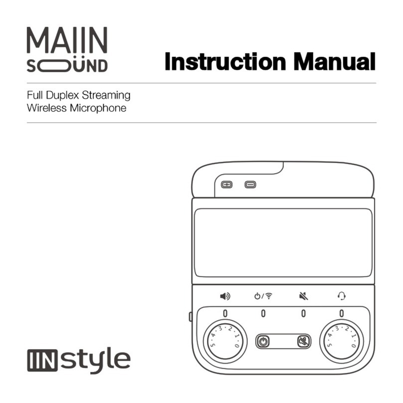
MAIIN SOUND IIN style instruction manual

MAIIN SOUND

MAIIN SOUND IIN style instruction manual

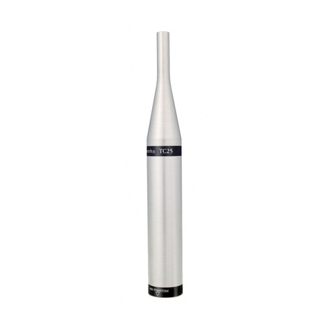
Earthworks TC25 user manual

Earthworks

Earthworks TC25 user manual

Sonova Phonak Roger Series manual

Sonova

Sonova Phonak Roger Series manual

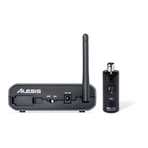
Alesis MicLink Wireless user guide

Alesis

Alesis MicLink Wireless user guide

manuals.online logo
manuals.online logoBrands
  • About & Mission
  • Contact us
  • Privacy Policy
  • Terms and Conditions

Copyright 2025 Manuals.Online. All Rights Reserved.

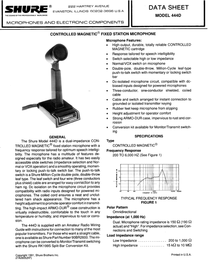
CONTROLLED MAGNETICm COMMUNICATIONS MICROPHONE
222 HARTREY AVE.. EVANSTON.
IL.
60204 U.S.A.
@
AREA CODE 3121866-2200
.
CABLE: SHUREMICRO
TWX: 910-231-0048 TELEX: 72-4381
GENERAL
DATA
MODEL
444
SHEET
COMMUNICATIONS
MICROPHONE
The Model 444 is a pressure-operated CONTROLLED
MAGNETIC@microphone. It is specifically designed for
radio communication applications and provides opti-
mum performance from single sideband transmitters
as well as AM and FM units. The response cuts off
sharply below 300 and above 3,000
Hz,
with a rising
characteristic to 3,000
Hz.
This special response char-
acteristic results in optimum speech intelligibility and
audio punch to cut through noise and interference.
i
Microphone Features:
A response tailored for single sideband transmis-
sions
w
A switch for instantaneous selection of Press-to-
Talk or VOX (voice-operated relay control) oper-
ation CONNECTIONS
.
Finger-tip control bar (locking or non-locking ac- Model 444 is designed for use with transmitters or
tion) to actuate microphone and an external relay amplifiers having high-impedance inputs. The
BLACK
or control circuit cable lead is the "hot" conductor for the microphone
circuit: the WHITE cable lead controls an external relav
.
~ong-lifeswitch to satisfy severe requirement of circuit. The shield is common to both the microphone
communication systems circuit and the external relay circuit. The shield should
be securely grounded to the amplifier or transmitter
Adjustable microphone height chassis ground. (See Figure
1
for internal wiring
w
A sturdy, high impact ARMO-DUR@base and mi- diagram of Model 444.)
crophone case
r\
Dependability-under all operating conditions
BLACK
GROUNDED TERMINAL
INTERNAL
CONNECTIONS
SHIELD
7
PRESS-TO-TALK SWITCH OPERATION
NORMAL-VOX OPERATION
6G-3
OF CARTRIDGE
-
Most amateur equipment is wired to use either VOX
(voice-operated relay control) or a Press-to-Talk switch.
Model 444 has been designed to provide maximum
flexibility for both types of operation. VOX or Press-
to-Talk operation may be easily selected by the
Normal-Vox slide switch on the bottom side of the
microphone base near the cable entry.
For Press-to-Talk operation of the microphone, the
Normal-Vox switch should be in the "Normal" position.
For VOX operation, the Normal-Vox switch should be
in the "VOX" position, and the Press-to-Talk switch
must be locked in the On position.
The finger-tip control bar can be used as a locking
m-----
i
\
!\
BLACK
or nonlocking switch. To use as a nonlocking switch,
I
I
;
!
WHITE
FIGURE
1
simply depress the control bar and release after trans-
mission. To use as a locking switch, depress the
PRESS-TO-
TALK
IMPORTANT
Shure Microphone Cables are selected after ex-
haustive tests to insure superior performance in micro-
phones because of low capacitance, superior shielding
properties and unusually long life under severe use.
Cables with plastic insulation should not be sub-
jected to excessive soldering-iron heat. Carefully clean
and tin the conductors and the connections to which
the conductors are to be soldered. The soldering
operation can then be done with a minimum of heat,
thereby avoiding any possibility of damage to the
cable.
\{
----
!:
SHIELD
NORMAL
-VOX
Copyright
1978,
Shure
Brothers
Inc.
27A245
(RJ) (OVER)
control bar and pull it forward. To unlock the switch,
t
SWITCH
-
-
iO1
?-
I,,)
SWITCH SHOWN IN
'NORMAL" POSITION
U.S.
Patent
D-198,850
Printed
in
U.S.A.
move the bar back and release.
YELLOW
j
SPECIFICATIONS
TYpe
CONTROLLED MAGNETIC@
Frequency Response
200 to 6,000 Hz (See Figure 2)
+
20
-
-
+I0
Z
Y
L
z
0
D
r
5
-10
Y
-20
1
I
I
I I l llllll
I
I IIIIIII
1
I
PO
w
100 lP00 lO.000 2opoo
FREWENCY
IN
HERTZ
TYPICAL
FREQUENCY
RESPONSE
FIGURE
2
Polar Pattern
Omnidirectional
lmpedance (at 1,000 Hz)
Microphone impedance is "High" for connection to
high-impedance microphone inputs
Load lmpedance Range
Minimum, 15 kilohms
Recommended, 100 kilohms
Output Level (at 1,000 Hz)
Open Circuit Voltage
........
-
53.0 dB* (2.25 mV)
Loaded with 100,000 ohms
...
-54.0 dB*
*O
dB
=
1 volt per microbar
Switch
Press-to-Talk switch-locking or nonlocking oper-
ation to actuate microphone and an external relay
or control circuit
Normal-Vox switch-single-pole double-throw slide
switch in microphone base to provide either voice-
operated relay control or Press-to-Talk microphone
operation
Cable
Non-detachable 2.lm
(7
ft), two-conductor shielded
plastic jacketed
Case
Two tone gray ARMO-DUR@
Dimensions
See Figure 3
6.4mmllI4 INITRAVEL
TO
OPERATE SWITCH
..........
OVERALL
DIMENSIONS
FIGURE
3
Net Weight
680 grams (1% Ib)
Packaged Weight
964 grams (2% Ib)
REPLACEMENT PARTS
Cartridge
....................................
R5R
Cable
....................................
70A293
Screen and Grille Assembly
..............
.90A1060
Press-to-Talk Switch
......................
.90A946
GUARANTEE
This Shure product is guaranteed in normal use to
be free from electrical and mechanical defects for a
period of one year from date of purchase. Please
retain proof of purchase date. This guarantee includes
all parts and labor. This guarantee is in lieu of any
and all other guarantees or warranties, express or
implied, and there shall be no recovery for any con-
sequential or incidental damages.
SHIPPING INSTRUCTIONS
Carefully repack the unit and return it prepaid to:
Shure Brothers Incorporated
Attention: Service Department
1501 West Shure Drive
Arlington Heights, Illinois 60004
If outside the United States, return the unit to your
dealer or Authorized Shure Service Center for repair.
The unit will be returned to you prepaid.