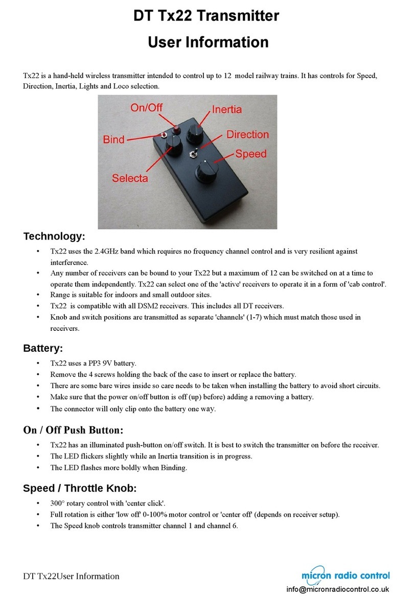
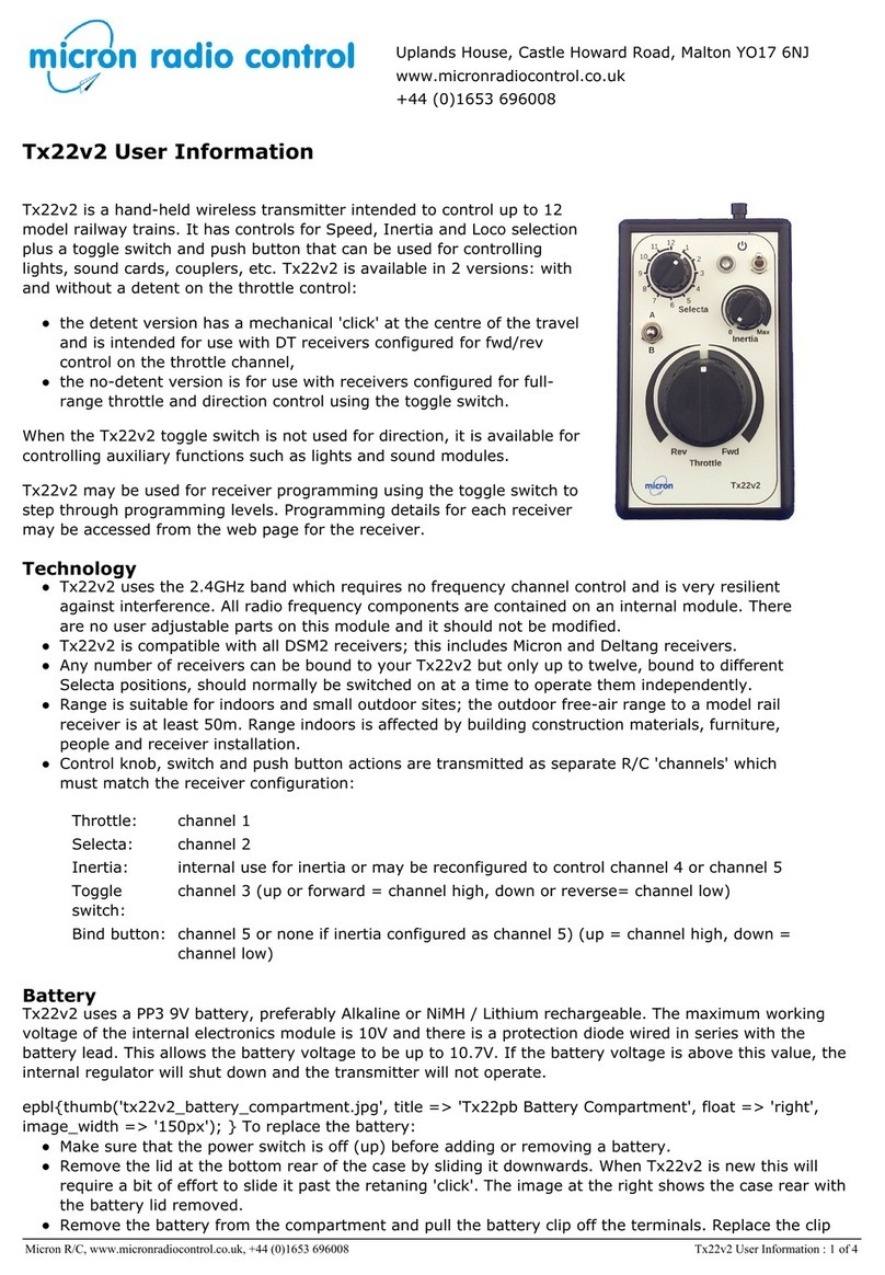
Micron Radio Control Tx22X Operation manual

Uplands House, Castle Howard Road, Malton YO17 6NJ
www.micronradiocontrol.co.uk
+44 (0)1653 696008
Tx22X User Information
Tx22X is a hand-held wireless transmitter intended to control up to 12
model railway trains. It has controls for Speed, Inertia and Loco selection
plus toggle switches and push buttons that can be used for controlling
lights, sound cards, couplers, etc. Tx22X is available in 2 versions: with
and without a detent on the throttle control:
the detent version has a mechanical 'click' at the centre of the travel
and is intended for use with receivers configured for fwd/rev control
on the throttle channel,
the no-detent version is for use with receivers configured for full-
range throttle and direction control using the toggle switch.
When the Tx22X S1 toggle switch is not used for direction, it is available
for controlling auxiliary functions such as lights and sound modules.
Tx22X may be used for receiver programming using the S1 toggle switch
to step through programming levels. Programming details for each
receiver may be accessed from the web page for the receiver.
Technology
Tx22X uses the 2.4GHz band which requires no frequency channel
control and is very resilient against interference. There are no user adjustable internal parts and it
should not be modified.
Tx22X is compatible with all DSM2 receivers; this includes Micron and Deltang receivers.
Any number of receivers can be bound to your Tx22X but only up to twelve, bound to different
Selecta positions, should normally be switched on at a time to operate them independently. The
Selecta function is available only on Micron and Deltang receivers.
Range is suitable for indoors and small outdoor sites; the outdoor free-air range to a model rail
receiver is at least 50m. Range indoors is affected by building construction materials, furniture,
people and receiver installation.
Control knob, switch and push button actions are transmitted as separate R/C 'channels' which
must match the receiver configuration:
Throttle: channel 1
Selecta: channel 2
Inertia: internal use for inertia or may be reconfigured to control channel 4 or channel 5
S1 switch: channel 3 (up or forward = channel high, down or reverse= channel low)
S2 button: channel 4 (up = channel mid, down = channel low)
Bind button: channel 5 (unless inertia is configured to control channel 5) (up = channel high, down =
channel low)
S3 switch: channel 7 (up or forward = channel high, down or reverse= channel low)
Battery
Tx22X uses a PP3 9V battery, preferably Alkaline or NiMH / Lithium rechargeable. The
maximum working voltage of the internal electronics module is 10V and there is a
protection diode wired in series with the battery lead. This allows the battery voltage
to be up to 10.7V. If the battery voltage is above this value, the internal regulator
will shut down and the transmitter will not operate.
Micron R/C, www.micronradiocontrol.co.uk, +44 (0)1653 696008 Tx22X User Information : 1 of 4

To replace the battery:
Make sure that the power switch is off (up) before adding or removing a battery.
Remove the lid at the bottom rear of the case by sliding it downwards. When Tx22X is new this will
require a bit of effort to slide it past the retaning 'click'. The image above shows the case rear with the
battery lid removed.
Remove the battery from the compartment and pull the battery clip off the terminals. Replace the clip
on the new battery which will only fit one way round. TAKE CARE, if force is needed, the connector is
probably the wrong way round.
Replace the battery cover by sliding it up from the bottom making sure that the retaining tab goes
under the case rear. The battery is held in place with a piece of foam attached to the cover and you will
feel some resistance as the cover is pushed down onto the battery.
On/Off Toggle Switch
Tx22X has a latching toggle switch for power with a separate indicator LED. Power is on when the toggle is
down. The LED lights continuously when the transmitter is on and flashes when Tx22X is in bind mode (see
below). It is best to switch the transmitter on before the receiver. If a receiver is switched on with Tx22X off,
it is likely to enter bind mode with rapid flashing of the LED on the receiver board. If you did not intend to
bind, switch the receiver off, then switch Tx22X on followed by the receiver.
Speed/Throttle Knob
The centre-off or low-off throttle type is actually implemented in the receiver. Transmitter difference are the
front-panel label and whether there is a centre-click on the throttle.
centre-off
Off/Stop is in the centre of rotation when the white dot is pointing toward the top of the transmitter; a
'click' will be felt as the knob is centred. Rotating the knob to the right (clockwise) will move your loco
forwards. If it goes in reverse, you need to swap the two wires connected to the motor in your loco.
low-off
Off/Stop is at the fully counter-clockwise rotation of the knob and speed increases at the knob is rotated
clockwise; the S1 toggle switch is used to control direction. The receiver will change the motor direction
only when the throttle knob is at zero.
Inertia/Momentum Knob
Unless reconfigured to operate R/C channel 4 or 5, the Inertia knob position is used internally to control
acceleration and deceleration. The Throttle knob sets a target speed and Inertia changes the transmitted
throttle value slowly until it reaches that target. The LED flickers while a change is in progress.
To stop quickly both Throttle and Inertia must be in the 'off' position. Inertia is off when turned fully
to the left.
Selecta
This is a 12-way rotary switch with positions matching those of a clock. It allows 12 locos to brought in and
out of service without touching them and requires a Selecta enabled receiver. Selecta uses R/C channel 2; a
receiver stores the value of channel 2 when it is bound. During normal operation, the received channel 2
value is compared with the stored value. If they match (plus/minus a small delta), the receiver responds to
the transmitter controls; if they don't match the receiver does not respond and, usually, the receiver LED will
show a double flash to indicate that is it not selected.
Bind Button
If a receiver has not previously been bound, it has to be 'paired' with the transmitter. Binding is only
required once per receiver.
1. Put your receiver into Bind mode (if a Micron or Deltang receiver, switch it on and wait for the LED to
flash fast).
2. Press and hold the Bind push-button on the transmitter.
3. Switch the transmitter on by pushing the Power button and then release the Bind button.
4. Binding is complete when the receiver LED stops flashing.
During normal operation, the bind button can be used as an auxilary control - e.g. horn or whistle sound
trigger. TAKE CARE to avoid holding the bind button down for 20 seconds or more as this will cause the
transmitter to enter calibration mode or reconfigure some of the controls.
Micron R/C, www.micronradiocontrol.co.uk, +44 (0)1653 696008 Tx22X User Information : 2 of 4

S1, S2, S3 and Bind Controls
The S1 and S3 toggle switches and the S2 and Bind push buttons can be used to control auxiliary functions
such as lights, sound module triggers, couplers, etc. via the P or F outputs on Micron or Deltang receivers.
Receiver programming is used to associate an action on one of these controls with a change to one or more
receiver outputs. Receiver programming is beyond the scope of this transmitter manual, you should refer to
the programming instructions for a particular receiver.
The S1 toggle switch can be used as a Direction switch to select forward/reverse with receivers that have
low-off motor control. Tx22X may be ordered with either a momentary (return to centre) or latching toggle
switches. All Micron receivers with a built-in speed controller can use either switch type for direction control
as the latching in forward or reverse is implemented in the receiver. If Tx22X is used for a live-steam loco,
the latching toggle switch should be specified.
Receiver Programming
Tx22X can be used to program Micron and Deltang receivers. The receivers have a rich set of functionality
which is not possible to describe here, refer to the receiver's programming instructions for details of the
available functions and the programming sequence to modify the functions.
The receiver must first be put into programming mode and then the Tx22X toggle switch is used to enter a
programming sequence. There are 2 methods of getting a receiver into programming mode:
1. place the controls for R/C channels 2 and 4 at the extreme positions and then switch receiver on, or
2. switch receiver on and enter the morse code SOS using the bind button (R/C channel 5)
Method 1 works for all receivers, method 2 is not supported by Deltang Rx4x receivers.
Method 1 (chan 2 and 4)
1. switch Tx22X on, receiver off
2. set the Inertia knob to control channel 4 (described above).
3. rotate the channel 2 (Selecta) and channel 4 (Inertia) knobs fully left or right (not centred).
4. centre the channel 3 (Direction) toggle switch.
5. put channel 1 (Throttle) in the 'off' position.
6. switch the receiver on.
7. the receiver LED will flash rapidly
8. centre the Selecta and Inertia knobs
9. the receiver LED will flash once, pause and repeat
Method 2 (SOS)
1. switch the Tx22X on and then the receiver, receiver LED must be lit
2. centre the toggle switch
3. wait at least 5 seconds without touching any transmitter control
4. tap out the morse SOS (... --- …) on the bind button where:
a dot is a short press of less than 0.7 second
a dash is a long press of about 2 seconds
pauses between dots or dashes is about 1 second
5. if the SOS is accepted, the receiver LED will flash once, pause and repeat
6. if the SOS was not accepted go back to step 3
To enter a receiver program sequence
A program sequence comprises 5 values, one for each column from the programming table. The Tx22X toggle
switch is used to enter the value for each level of the sequence, the receiver LED flashes to show the digit
value. Program data is modified by pulsing channel 3 low (toggle down or reverse) and stored by pulsing
channel 3 high (toggle up or forward).
Modify programme
sequence value:
Pulse the toggle switch down.
The rx LED will briefly show rapid flashing and then the next flash in the sequence
– i.e. if it was showing 1-flash it will now show 2-flash. The flash sequence returns
to 1-flash when advancing beyond the last value in a sequence. The number of the
last value depends on the particular sequence being programmed.
Micron R/C, www.micronradiocontrol.co.uk, +44 (0)1653 696008 Tx22X User Information : 3 of 4

Store programme
sequence value:
Pulse the toggle switch up.
The rx LED will briefly show rapid flashing and then show the currently
programmed flash pattern for the next in the sequence. If this is the last value in
the program sequence, there is a brief pause with the LED off while the changes
are written to safe storage and then the LED comes on solid.
Repeat the above for each program function that you wish to alter.
For example, to set the ESC output (the first if the receiver has multiple ESC) to respond to full range
throttle on channel 1 and direction control on channel 3, the programme sequence is 1,1,2,1,3:
Enter programming mode
Rx LED displays 1-flash, push S1 toggle up to accept
Rx LED displays 1-flash, push S1 toggle up
If rx LED does not display 2-flash, push S1 toggle down until it does, push S1 toggle up
If rx LED does not display 1-flash, push S1 toggle down until it does, push S1 toggle up
If rx LED does not display 3-flash, push S1 toggle down until it does, push S1 toggle up
Rx LED lights solid
Calibration
All ready-to-use transmitters are calibrated as the final manufacturing step. This sets the throttle control
centre position and normally only needs to be done once. If you suspect that the throttle control is not
operating correctly or you have replaced any of the internal components (e.g. throttle potentiometer), your
transmitter may need calibration.
If the bind button has been inadvertently held down for longer than 20 seconds, the previously stored
calibration data will have been overwritten and you could find that the throttle control behaves strangely.
To perform calibration:
Centre the Throttle knob
Rotate the Selecta switch to position 6 (pointer on knob is pointing vertically down)
If the toggle switches are latching type, ensure they are in the centre
Set Inertia to off
Switch the Tx on
Within 60 seconds, press and hold the Bind button
After 20 seconds, the Tx LED will:
go out for 2 seconds; come on for 3 seconds; go out for 2 seconds; come on for 3 seconds; go off
and stay off
Release the Bind button, the Tx LED will stay on
The transmitter controls are now calibrated.
Change Inertia Control Function
If the Bind button is pressed for more than 20s, it alters how the Inertia knob is used:
if the Bind button is pressed for 20s or more within the first 60s of switching on, it will perform
calibration of the throttle knob centre position
if the Bind button is pressed for 20s or more after the first 60s of switching on, it will toggle what the
Inertia knob is used for – Inertia or control of channel 4 or channel 5.
The default behaviour of the Inertia knob is to control acceleration and deceleration as described above. To
toggle the Inertia knob function:
1. switch the Tx on and wait 90s without touching the Bind button
2. press and hold the Bind button
3. after 20s the power LED will go off for 2s and then come on for 3s; release the Bind button in this 3s to
toggle the Inertia knob between controlling Inertia or controlling channel 4.
4. after a total of 25s (i.e. after the 3s of LED on) the power LED will go off and stay off until you release
the Bind button; this causes the Inertia knob to control channel 5
5. repeat steps 1 to 3 to revert to the Inertia knob controlling throttle inertia.
If the Inertia knob is being used for Inertia or channel 4, the Bind button controls channel 5 if pressed for
less than 20s. If the Inertia knob is being used for channel 5, the Bind button has no effect on channel 5 but
is still used for binding and controlling what the Inertia control is used for.
Micron R/C, www.micronradiocontrol.co.uk, +44 (0)1653 696008 Tx22X User Information : 4 of 4
Table of contents
Other Micron Radio Control Transmitter manuals
Popular Transmitter manuals by other brands

Verkaufsgesellschaft
Verkaufsgesellschaft FIT2-868 Installation and operating instructions

JUMO
JUMO HART dTRANS p20 Ex d operating manual

WIKA
WIKA IPT-10 operating instructions

EMERGENCY BEACON CORPORATION
EMERGENCY BEACON CORPORATION EBC-406HM Instruction and maintenance manual

Kramer
Kramer TP-210A user manual

ADEMCO
ADEMCO 5818 installation instructions