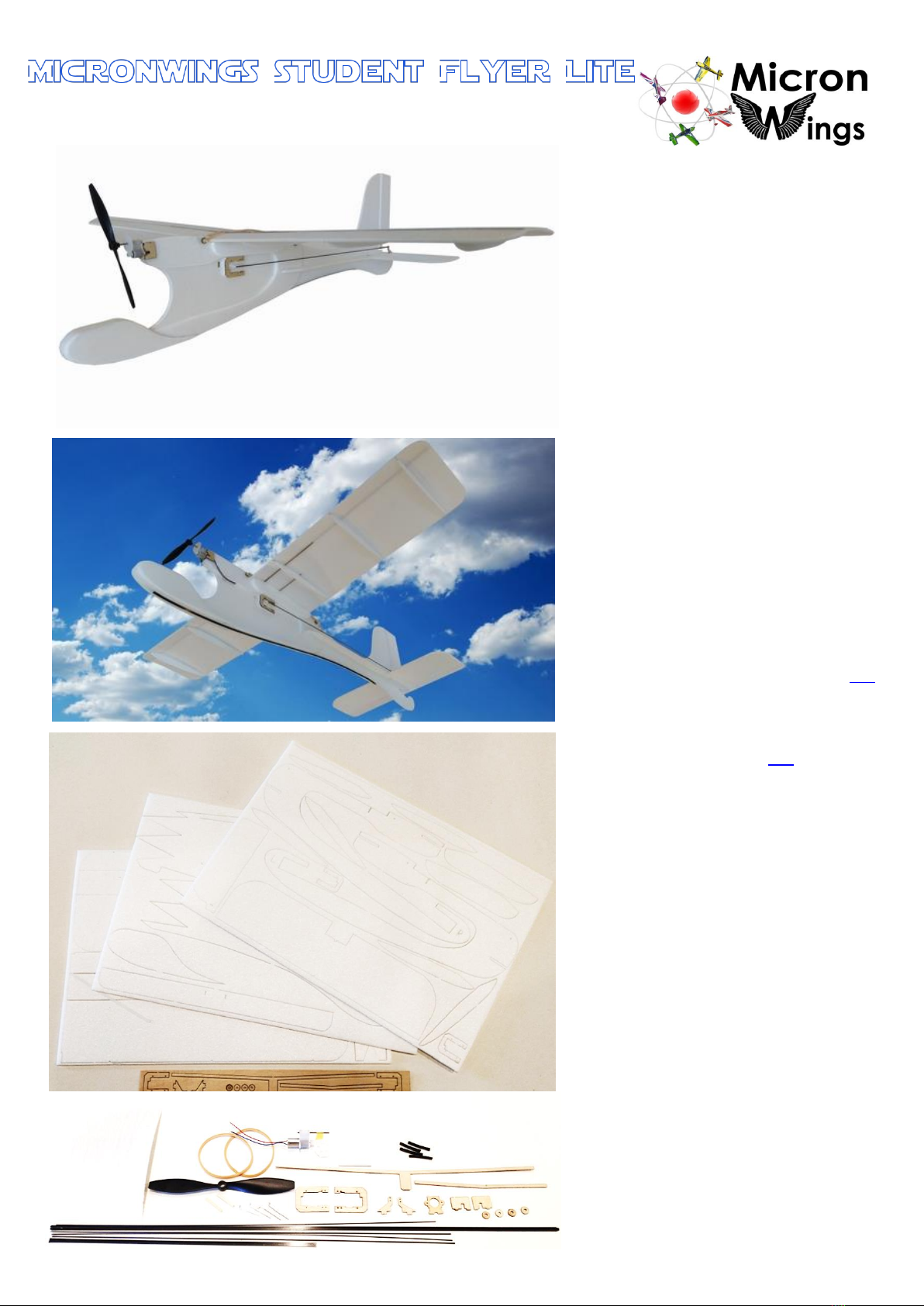
Micron Wings Student Flyer Lite Manual

(Build Instructions)
Specifications
* Wingspan: 56cm
* Length: 50.5cm
* Flying Weight: 44 grams
* Channels: 3 (Rudder Elevator Throttle)
* Suggested Receiver: 4Ch Micro
* Motor: 7mm GearDrive (Supplied)
* Prop: GWS 4040 (Supplied)
Included in Airframe Kit
* Airframe Parts
* Geardrive, motor and prop
* Wooden Wing Braces
* Wooden Servo Mounts
* Carbon Struts
* Control Horns and Linkages / Pushrods
* Sandpaper
* Double Sided Mounting Tape
* Rubber Bands
Needed to Complete
* Hot Glue Gun
* Epoxy Glue
* UHU Expanded Polystyrene Glue (link)
* Hobby Knife
* Pliers to cut carbon rod
* Ruler (preferably steel)
* Blenderm Hinge Tape (link)
* Masking Tape or Household Pins
* Soldering Iron to heat the heat shrink
* Sanding Block
* Micro Screwdriver
* Battery Charger and Batteries
* Transmitter, Receiver and Servos
(see website for suggested RC setup)

Before You Start
This airframe has been designed with school students and first time indoor flyers in mind. The
build process is simple, but some careful sanding of the parts is necessary. Follow the instructions
below for a trouble-free build process.
Two main types of glue are required for this build and each type of glue has its specific purpose.
Use UHU Expanded Polystyrene glue on all joints except where Glue Gun Hot Glue is specified.
Glue Gun hot glue is used when we need to fill a void or gap
around the part we are gluing.
UHU Expanded Polystyrene Glue is used for bonding foam
and wooden parts together. UHU is usually applied to both
surfaces and allowed to dry before bringing the surfaces
together for an instant bond.
However, in some cases where we need to parts to move against each other as we bring them
into position, for this we don’t allow the glue to dry before bringing the parts together or we may
just add a thicker layer of glue to one surface.
A note on using UHU Expanded Polystyrene Glue
When applying this glue, most people use too much glue. You should apply the glue straight from
the tube and then spread or thin it out with a piece of scrap foam to leave just a thin film of glue
on the surface. If you put too much glue on, scrape some off before gluing the parts together.
Use a sharp hobby knife to cut the parts from the sheets.
This is too much glue. It won’t dry
properly and the joint will be weak.
The correct amount of glue.
A thin film of glue on the surface.

The tail surfaces and matching control surfaces
where they meet need to be cut at an angle on one
side to allow them to pivot. To do this, place a
metal ruler on top of the surface flush with the
edge and press down as you cut at a 30 degree
angle back underneath the ruler. The control
surfaces will look like this from the edge.
These are the surfaces which need to be cut at 45 degrees. Lay the rudder control surface and tail
section out like this to ensure you cut the correct side of each surface.
-----------------------------------------------------------------------------------------------------------------------
Sand the tail plane and rudder control surfaces on
all edges on both sides.
(except the edges you just cut the 45 degree bevel into)
Laying the longer edges flush with a table edge will
support the surface while you are sanding.
You may choose to simply bevel both sides or you may wish to make them more rounded.
These are the surfaces you need to bevel on both
sides.
-----------------------------------------------------------------------------------------------------------------------
The wings have a top and a bottom. The top of the
wing has these half cut lines.
Sand a bevel into the wings on three sides except
this edge where the wings will join together.
Once again, put the wing on the edge of a flat
surface to support it as you sand.
Sand a bevel on the top surface which goes down at least half way at this angle.
Then sand a smaller bevel on the lower surface.
You may wish to further sand the edge to round the bevel off (this is optional)

An example of the completed surface
The wings will form a V shape when glued together as
indicated by the plywood wing struts. So we need to
sand the ends of the wings to have a “VERY SLIGHT”
angle. This angle only needs to be about 2 degrees as
shown below so just a few rubs of the sandpaper is
adequate.
Note: if you hold the wings together at this stage there will be a large gap in the middle, but this
gap will disappear when the leading and trailing edges are bent.
-----------------------------------------------------------------------------------------------------------------------
To give the wings an airfoil shape we need to bend
them along the half cut lines. Support the wing on
the edge of a table and use a ruler to evenly bend
the wing at both of the half cut lines.
Bend it down about 30 degrees till you hear the
foam crack.
Glue 3 ribs in place under each wing. The notches
indicate the position of each rib. Make sure the ribs
run at 90 degrees to the leading edge of the wing.
The side of the rib with the three straight edges is
glued to the wing.
Sand the plywood locating former to bevel it on both
sides. This will allow it to slot into the groove on the
fuselage easily without damaging the foam.
Glue the wooden wing spars to one wing. On the
longer one, only apply glue to the wooden wing spar
at the back. For the shorter rear one, apply glue to
both sides of it.
Make sure the wing spars are flush with the top and
bottom surfaces of the wing.
Apply glue to both surfaces where the foam wings
join in the middle as well as to one side of the longer
plywood wing spar and both sides of the shorter one.
Then glue the wings together as shown.
About 2 degrees
Glue only this side of the
wooden spar to the foam
Apply a strip of Blenderm hinge tape along the
middle of the wings to hold them flush.
Glue here on this side
Don’t glue here on this side

Sand the three foam sections under the wing where
the wings join to take the ridge off and flatten the
surface there a little.
Glue these two sets of pieces together as shown in
the photo.
Glue these pieces under
the wings as shown.
Note the correct
orientation of the front
piece as shown here.
Use UHU Expanded Polystyrene glue to glue in place
the two carbon wing rods in the gap toward the
front of the wings. These are glued into the grooves
where the foam bends and also to the longer
wooden wing spars. Apply the glue to the carbon
rod and then press the carbon rod down into the
gap so it is level with the top of the wing surface.
Wipe off any excess glue with a scrap piece of foam.
Glue the fuselage pieces together and lay it on a flat
surface to keep it straight as it dries.
Apply glue to both sides of the 188mm long x 3mm
wide carbon strip and press it into the slot in the
fuselage while the glue is still wet. Allow to dry.
NOTE: Wing rods are the shorter rods

Glue in place the two side pieces. For these, just
apply the glue to the side piece and spread it out
thin. Then align it with the main centre piece of the
fuselage. If you place it on very gently without
pressing it down, it will be able to be moved a little
to get it in the correct position.
Take your time with this stage. The gaps must
match exactly and the top of the side piece must
be perfectly flush with the top of the fuselage.
Ensure that this slot is aligned on all pieces and
forms a 90 degree angle with the fuselage.
Use wood glue to glue the motor mount parts
together as shown here and allow to dry.
Glue the motor mount in place with foam glue as
shown here. Note the orientation of the mount and
ensure the hole in the front is aligned with the gap
in the foam for the motor.
There will be a gap here for the motor wires to
protrude through.
At this point check that your battery fits firmly into
the battery slot. If it’s loose, add some foam
padding so it slides in firmly.
90 degrees
Must be flush with top

Glue the battery covers to either side of the nose
section of the fuselage.
Put a very small amount of UHU Expanded
Polystyrene Glue on the longer flat carbon strip and
some down the middle of the fuselage as well. Allow
the glue to dry well (about 15 minutes) and then
attach the carbon strip as shown. Start a few
centimetres back from the front of the fuselage.
Glue on the wing supports.
Note that the wing supports must be flush with the
body parts below as shown here.
At the front the corner lines up with the sit-down in
the body.
At the back, the wing support will be raised up
about 2mm.
Use hinge tape to attach the control surfaces and
glue the control horns in place.

Glue in the tailplane checking that it is horizontal
Glue the horizontal body parts onto the body and
tailplane. Slide them back to fill any gap between
them and the horizontal stabiliser.
Reinforce the joint with some Blenderm hinge tape
top and bottom.
Glue the wooden linear servo mounts onto the foam
supports.
Refer to the linear servos you are using. Remember
that the pushrod exits the servo the opposite way to
the gear at the front.
Ensure that the cut-out in the servo mount matches
the orientation of your linear servo.
Glue the servo mounts on the fuselage just behind
the hole. Ensure they are parallel with the wing
support. However, you may wish to leave a 1mm
gap between the servo mount and the wing support
to run your servo wires neatly.

Sand the ends of the round wooden pegs to round
the ends off. Then insert them into the airframe in
front and behind the wings.
Fill these two holes up with Hot Glue to secure the
pegs in place.
Glue the round supports in place as well with UHU
Expanded Polystyrene glue.
Fit the propeller, receiver and servos and route the
wiring.
Some paper motor mount spacers have been
provided with the kit. Use these behind the left
hand side of the motor mount to give the motor a
slight amount of right thrust. You will most likely
only need to use one spacer but this will also
depend on the alignment of the motor mount itself.
This image shows the correct amount of right thrust.
Ensure that there is no more right thrust than shown here.

Check if the servos need to be reversed on your
transmitter settings and centre all trims.
Use a ruler to make sure the control surfaces are
level with the horizontal and vertical stabilizers.
Use some pins or wrap some masking tape around
the ends of the pivot joint to hold the control
surface level. This will keep it in the correct position
while we attach the pushrods.
Attach the Z links to one end of the 30 cm long
carbon pushrods. You may wish to use a small
amount of UHU Expanded Polystyrene glue under
the heat shrink to form a strong bond when the heat
shrink is heated up and shrunk.
Attach these rods to the servos and lay them along
the fuselage on top of the elevator.
Trim the pushrods to be about 5mm short of the
hole in the control horn.
Use the heat shrink and Z links to attach the control
horns.
Remove tape from control surfaces before testing.
Adjust the trim on the transmitter if any small
adjustments are needed to ensure all control
surfaces are level with their stabilizer surface.
Attach the wings with rubber bands and check that
they are at 90 degrees to the fuselage and level with
the tail plane. If the wings are not level, lightly sand
down the foam wing support on the high side till the
wings sit level.
Attach the wings to the airframe.
The centre of balance should be 38mm from the
leading edge of the wings. Insert battery and add
any necessary ballast to the nose.
38mm

You will most likely need to dial down the
amount of throw on the control surfaces. Most
good transmitters allow you to do this. Use
these images as a guide as to how much throw
is required. In particular on the elevator, don’t
exceed this amount of throw.
-----------------------------------------------------------------------------------------------------------------------
Next you may wish to sand down the fuselage.
If you intend mounting an FPV camera on the front,
keep this part flat.
Airframe Overview Video Flight Video
Flight Video –In the Playground
Copyright © MicronWings 2019: All rights reserved.
This manual is for personal use only. No unauthorized copying or digital distributing permitted
without permission from MicronWings.
Other Micron Wings Toy manuals

Micron Wings
Micron Wings Falcon User manual

Micron Wings
Micron Wings Balsa Craft S.E.5a Manual

Micron Wings
Micron Wings Balsa Craft Cub Manual

Micron Wings
Micron Wings FreeSpirit User manual

Micron Wings
Micron Wings SkyFox User manual

Micron Wings
Micron Wings Balsa Craft Kits LiteStick Manual

Micron Wings
Micron Wings MINIMUM RC J3 CUB User manual

Micron Wings
Micron Wings Minimum RC A6M2 Zero User manual

Micron Wings
Micron Wings Sopwith Pup Manual

Micron Wings
Micron Wings Student Flyer User manual