manuals.online logo
Brands
  1. Home
  2. •
  3. Brands
  4. •
  5. Micron Wings
  6. •
  7. Toy
  8. •
  9. Micron Wings Balsa Craft Cub Manual

Micron Wings Balsa Craft Cub Manual

Cub (Build Instructions)
Before You Start
This airframe has been designed to fit together easily with all components precision drilled and
CNC cut from high quality balsa and paulownia wood. However, you will be working with very
small components, so you will need patience and keen eyesight. We recommend working in a very
well-lit area and taking a break between stages to rest the eyes and hands. Most of all, take your
time, enjoy the building experience and you will be proud of what you have produced in the end.
Specifications
Wingspan: 37.5cm
Length: 27.5cm
Flying Weight: 25 -28grams
Channels: 3 (Rudder Elevator Throttle)
Suggested Receiver: 3 - 4Ch Micro
Airframe Kit
(Included Contents)
* Airframe Surface Parts (balsa)
* Airframe Skeleton (hardwood)
* Carbon pushrods
* Control linkages / heat shrink
* Undercarriage with Wheels
* Fine sand paper
* Decal Stickers
* Geardrive with 7mm Motor
* Propeller
Needed to Complete
* Thick CA Glue or UHU Hart Glue
* Slow-Drying White Model Glue
* Micro Phillips Head Screwdriver
* Hobby Knife
* Ruler
* Pins
* Fine Point Tweezers
* Hobby Masking or Other Tape
* Receiver Transmitter Charger Battery
(see instructions for suggested RC gear setup)
First, refer to this and the following pages to ensure that you have all the required airframe
components in your kit.
Decal Stickers
Airframe Wooden Parts and additional parts
Before starting you may wish to very lightly
sand down all the flat surfaces of the parts if
you want to have a smooth finish. It’s easier
to do this initially, otherwise the ribs will get
in the way of sanding when complete.
When removing parts from the sheets, identify where the cut line is sectioned and cut that part
with a sharp pointed hobby knife. The parts should be able to be removed easily. Never twist or
bend the parts back and forth to remove them as this will damage the parts. Instead cut around
the parts as necessary to easily remove them.
Remove the ribs from the hardwood sheet and glue these in place to the wings.
Note: If you are choosing to put any decals on your wings and in particular on the underside, it
will be difficult to attach them once the ribs are glued in place. You may wish to attach the decals
before you glue the ribs in place. If doing so, glue in all the ribs except the ones which will go
directly over the decals. This will give the wings their curve before attaching the decals. The
decals can then be applied to the curved wing and they will sit flat on the wing surface. Once the
decals are attached, go ahead and glue the final ribs in place. See image below to identify the
leading edge before gluing the ribs in place. Also lay your wings out with the centers together and
ensure you don’t make two left or two right wings by gluing the ribs to the same side of the wing
on each side.
It is a good idea to use Model Masking Tape
to hold down the ribs while they dry.
Product Link
Leading Edge
Example of a decal attached and the rib
glued in place over the top of it.
Make sure you have two opposite wings and not
two left or right wings.
We recommend UHU Hart Glue (Product Link)
Lay out your tail-plane pieces and work out which
side the control horns will need to go on.
You will need to connect up your receiver and
servos if using independent servos and look at
which side the elevator and rudder are on.
Remember that the pushrods will be on the upper
surface of the tail-plane.
The kit comes with a pack of tape hinges as shown
on the right below. These are stuck in place on the
tail surfaces. Don’t stick them where the wood is
joined –stick them over the gaps in the wood. Use
three for the elevator –one on each side toward
the tip and one on the inner part near the hinge.
Use the other two for the vertical stabilizer. Use a
hobby knife to separate the sticker from the paper,
and use tweesers or the blade of a hobby knife to
fit them in place instead of trying to do it with your
fingers.
Glue the vertical stabilizer onto the tail-plane and
set aside to dry. You can use two match stick boxes,
one either side of the vertical stabilizer to hold it
vertical while drying.
Next we will start on the fuselage. Take the two
sides and lay them on a flat surface. Glue the
window surrounds in as shown.
At this stage you can also attach the wheels to
the undercarriage and secure them in place with
some 0.6mm heat shrink. Heat carefully with the
tip of a soldering iron to shrink the heat shrink.
The front body former is shown here. It has
three screw holes for attaching the screws which
hold the undercarriage in place. It is easier to
screw these screws in place now and check the
undercarriage attaches firmly. Use the larger of
the screws in the pack (the smaller ones are not
used –they are supplied because they are used
for the motor mount). The screws are not
screwed all the way in and the undercarriage
slips in behind them.
Start building the fuselage frame. Glue the three pieces in the image on the left below together.
Next glue in part “T” and part “L” (Part “M” is inside part “L” on the sheet – don’t misplace it!)
Finally glue in place part “G” with the motor mount slot in it. Note the orientation with the motor
slot skewed off to the right hand side of the plane. This part also slopes down about 10 degrees.
Three screws
Orientate this piece so the three tongues are toward the front.
These three tongues are glued into the three slots in the front former.
Take note of the orientation.
Part: T
Part: L
From above –the slot for the motor is slightly pointing to the
right. This is to give right thrust to the motor to counter the
torque of the motor which tend to turn the plane to the left.
Next glue in lace part “M” at the front.
Also slightly bend back this part at a small
angle.
Crease the airframes along the dotted lines.
Make sure you have the sides laid out on the
table as shown in the image so they both bend
inward.
Put one side on without glue first and check
that all the slots line up and that it all fits
together okay. Then apply glue to the body
former frame and glue one side on. Glue the
part that was pushed back slightly so it goes
between the windows. We suggest using
Aquadhere glue (White balsa glue) for this part
because it dries slower and gives you time to
work.
Then, glue in place the remaining body
formers as shown here. These body formers
should be angled back about 5 degrees
because the side of the fuselage will bend in to
meet the other side at the back. So you want
these body formers to go straight acros the
body when those two sides are brought
together.
Part: M
Bend back slightly
Finally, using slow drying glue again, glue the
opposite fuselage side on. Use some model
masking tape to hold the sides in place while
this part dries.
At this stage do not glue the two ends of the
fuselage at the back together. A tail skid will
be glued in there later.
Next glue in the supports on either side of the
nose on the inside. These should be flush with
the outer wall of the fuselage. If not then sand
the long straight edges until the curved edge
sits flush with the fuselage sides as shown in
the image.
Glue in place the bottom nose cone piece.
Wet this piece with a few drops of water on
both sides and allow a few minutes for it to
soak in. Then bend it carefully around the
curve and secure it in place with model
masking tape until the wood has dried out and
it holds its shape. Then glue it in place.
Glue the top nose cone in place.
Glue in the front windscreen.
Then glue in the wing brace. There are two
slots in the fuselage sides for it to fit into as
well as two in the fuselage frame. Make sure
the brace sits down into the locating slots and
that it is flush with the top of the fuselage
walls.
Flush with top
Remove the piece of scrap balsa from the front
of the bottom plate.
Glue the bottom plate in place. We recommend
using a slow drying glue to allow time to work.
Also use model masking tape to hold the joints
firmly together.
Glue the tail skid in place as shown.
Glue the top plate in place. We recommend
using a slow drying glue to allow time to work.
Also use model masking tape to hold the joints
firmly together.
Carefully cut out the bottom cover with a fine
hobby knife. Glue the hardwood part on the
right in the image onto the cover. Allow the
two tongues to protrude. These are for locating
and securing the cover in place.
There are two corner marks on the cover to help you align the hardwood piece.
Glue in the magnet into the balsa cover and the other magnet into the hardwood part.
Smear some glue over both sides to help hold these in place.
After this unit has dried gently sand the edges of the cover bay and the cover itself to allow it to
fit easily.
Glue in the hardwood piece with the magnet
attached. But check which way this needs to be
glued in. Remember the magnets need to
attract to close the door.
After allowing to dry well your hatch should fit
like this. You may choose to use some of the
scrap balsa from the kit to add some
strengthening to the inside surface of this hatch.
At this stage you may want to sand down the
corners of the parts you just glued on. They
will be easier to sand down now than after the
wings and tail-plane are attached.
Remember not to sand down the area where
the wings and tail-plane attach.
You are now ready to glue the tail-plane in
place. Ensure it is level.
The gear mounting board can be used to mount the receiver on the top side and the battery on
the bottom side. Place some hook and loop tape on either side of the board as shown below.
Receivers
The kit doesn’t come with a receiver or servos so it is up to you to choose which one is best for
your needs. You may have a receiver from another model which you can fit. The two receivers
below are suggested for this model.
Option1 –Micro Receiver for Servos Option 2 –Brick Style Receiver
Receiver 4Ch DSMX With 2A ESC Receiver 24R6CLV11 DSM2 Brick
Product Link Product link
Servo 5320 Black SH
Product Link
As an example in this manual we will outline the procedure for setting up Option 1 with separate servos.
Mount the receiver to one side of the mounting board.
Servos can be screwed into the frame from the top
where the wings attach.
Also mount the geardrive as shown here and feed the
wires through to attach to the receiver. You may need
to widen the gap between the spur gear and the hub
to make sure it has clearance with the balsa frame.
Use the short arms
with 2 holes
Use the outside positions with
the servo arms facing inward.
The motor is supplied with no connector.
Depending on your choice of receiver you may
wish to solder the wires directly to the receiver
board or attach a connector which matches the
one on your receiver. See the connectors section
on our website for various options.
Link to Connectors page on MicronWings
With the receiver all wired up you can now screw
the mounting board in place.
The battery can be mounted directly under the
receiver board.
The kit is supplied with two types of control linkage connectors and you may choose which ones
you want to use. The wooden type on the left screwed into the servo arms. However we suggest
you use the linkages shown on the right which are a more reliable way to set up your control
system. The kit is also supplied with two carbon pushrods.
Battery Info: We recommend a 130mah battery such as the
one below. These are available on the MicronWings website
for postage within Australia only.
Product Link
First, turn on your radio gear and make sure the servos are
centered and all trims are set to neutral. Then attach the
pushrods to the servos first. If using the control linkages
(non-wooden type) use the clip type one to attach to the
servo end. These linkages can also be glued in place just to
make sure they don’t come off, but still cover them with
heat shrink and shrink it with a soldering iron tip.
Once this is done attach the linkages with a hook in them to the control horn and trim your carbon
rod. Then use a small amount of glue and the larger 1mm heat shrink to secure them in place.
You may use a soldering iron tip to heat the heat shrink.
The finished linkages should look like this. Heat shrink is used to secure the joints and the U
shaped hook can be used to make fine adjustment later (similar to the effect of using trim on the
transmitter)
These wooden sections are then cut out to allow the control surface to move. Finally test your
control surfaces with the receiver turned on. You may need to dial down the throw so the control
surfaces don’t move too much.
Adjust your elevator travel on your transmitter so that it clears the
rudder. Also check your rudder throws. The rudder should move just
15 degrees either side of center.
This will usually require you to dial down your rudder throws. Start
with small throws for test flying and increase as needed.
Note: Control linkages attach to the outermost hole
Make two cuts to cut
out the block like this
Don’t forget to cut out here as
well from underneath
Cut out
Adequate gap
Next attach the prop.
Additional O-rings can be purchased on the MicronWings website.
Product Link
Next glue in place the central section for the wings. Once
again tape it down with model masking tape and allow to
dry.
Note that after attaching this section you will no longer be
able to easily access the servos or receiver to make
adjustments without unscrewing the bottom mounting
plate from underneath.
Glue on the wings ensuring they are level and have the
same dihedral angle. Insert some pins on a steep angle at
the locations shown here to hold the wings flush with the
centre cover as it dries.
Your airframe is now complete
Balance Point.
Attach your battery and use it’s position to adjust the balance point. The balance point should be
20mm from the leading edge of the wing.
Decorating
We have supplied a range of stickers in this kit. So you can dress it up with the following styles.
Lively Red and Blue Theme Traditional Basic Cub Theme
20mm
Basic Overview Video
A quick look over the Cub on the bench.
Sample Flight Video.
A few quick take-off and landing filmed outside in calm conditions.
Copyright © MicronWings 2017: All rights reserved.
This manual is for personal use only. No unauthorized copying or digital distributing permitted
without permission from MicronWings.

Other Micron Wings Toy manuals

Micron Wings Glider V-Tail Bellbird User manual

Micron Wings

Micron Wings Glider V-Tail Bellbird User manual

Micron Wings Student Flyer Lite Manual

Micron Wings

Micron Wings Student Flyer Lite Manual

Micron Wings Minimum RC A6M2 Zero User manual

Micron Wings

Micron Wings Minimum RC A6M2 Zero User manual

Micron Wings FreeSpirit User manual

Micron Wings

Micron Wings FreeSpirit User manual

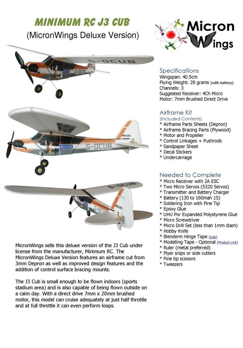
Micron Wings MINIMUM RC J3 CUB User manual

Micron Wings

Micron Wings MINIMUM RC J3 CUB User manual

Micron Wings Soarer User manual

Micron Wings

Micron Wings Soarer User manual

Micron Wings Depron Bug Airframe Kit V2 Manual

Micron Wings

Micron Wings Depron Bug Airframe Kit V2 Manual

Micron Wings Student Flyer User manual

Micron Wings

Micron Wings Student Flyer User manual

Micron Wings Sopwith Pup Manual

Micron Wings

Micron Wings Sopwith Pup Manual

Micron Wings Balsa Craft Kits LiteStick Manual

Micron Wings

Micron Wings Balsa Craft Kits LiteStick Manual

Micron Wings Minimum RC F8F Rare Bear User manual

Micron Wings

Micron Wings Minimum RC F8F Rare Bear User manual

Micron Wings Ezee Flyer User manual

Micron Wings

Micron Wings Ezee Flyer User manual
Micron Wings SkyFox User manual

Micron Wings

Micron Wings SkyFox User manual

Micron Wings Balsa Craft S.E.5a Manual
Micron Wings

Micron Wings Balsa Craft S.E.5a Manual

Micron Wings Falcon User manual

Micron Wings

Micron Wings Falcon User manual

Popular Toy manuals by other brands

Mega Bloks Barbie Build'n Style Art Teacher Teresa quick start guide

Mega Bloks

Mega Bloks Barbie Build'n Style Art Teacher Teresa quick start guide

Billing Boats CUX 87 BB474 Building Instruction

Billing Boats

Billing Boats CUX 87 BB474 Building Instruction

Fisher-Price Y6590 instructions

Fisher-Price

Fisher-Price Y6590 instructions

Fisher-Price CGN57 instruction sheet

Fisher-Price

Fisher-Price CGN57 instruction sheet

Chicco ROCK-a-BEE user guide

Chicco

Chicco ROCK-a-BEE user guide

Italeri F-14A Tomcat 50th First Flight Anniversary Assembly instructions

Italeri

Italeri F-14A Tomcat 50th First Flight Anniversary Assembly instructions

KID Trax KT1094TR owner's manual

KID Trax

KID Trax KT1094TR owner's manual

Trix BR 45 manual

Trix

Trix BR 45 manual

Fisher-Price GeoTrax V8491 instructions

Fisher-Price

Fisher-Price GeoTrax V8491 instructions

Same Toy 2117UT manual

Same Toy

Same Toy 2117UT manual

Faller 222171 quick start guide

Faller

Faller 222171 quick start guide

Rollplay W348 Owner's manual and assembly instructions

Rollplay

Rollplay W348 Owner's manual and assembly instructions

LEGO 5795 instructions

LEGO

LEGO 5795 instructions

LEGO CLASSIC 10715 manual

LEGO

LEGO CLASSIC 10715 manual

marklin 37446 user manual

marklin

marklin 37446 user manual

Fisher-Price Y3630 quick start guide

Fisher-Price

Fisher-Price Y3630 quick start guide

Makeblock HaloCode Sample Project Guide

Makeblock

Makeblock HaloCode Sample Project Guide

VTech Baby Twist & Hug Koala Rattle Parents' guide

VTech Baby

VTech Baby Twist & Hug Koala Rattle Parents' guide

manuals.online logo
manuals.online logoBrands
  • About & Mission
  • Contact us
  • Privacy Policy
  • Terms and Conditions

Copyright 2025 Manuals.Online. All Rights Reserved.