Fullwood Revolution II Stage 3 User manual

Revolution II Stage 3
Installation Instruction
Technical Manual
Revision C
ORIGINAL MANUAL

Ref / Pt.No: 006944
Revolution II Stage 3 Installation
Instruction
Revision: C
Date: 27-Nov-12
006944.doc Page 2 of 29
Contents
Revolution II Stage 3 Installation Instruction......................................... 1
Contents ................................................................................................... 2
Important information - read this first .................................................... 3
Icons ......................................................................................................... 3
1. Safety............................................................................................. 4
2. Bail/Cabinet Part Numbers........................................................... 5
3. Bail Assembly ............................................................................... 6
3.1 Rope Guide Plate...............................................................................................6
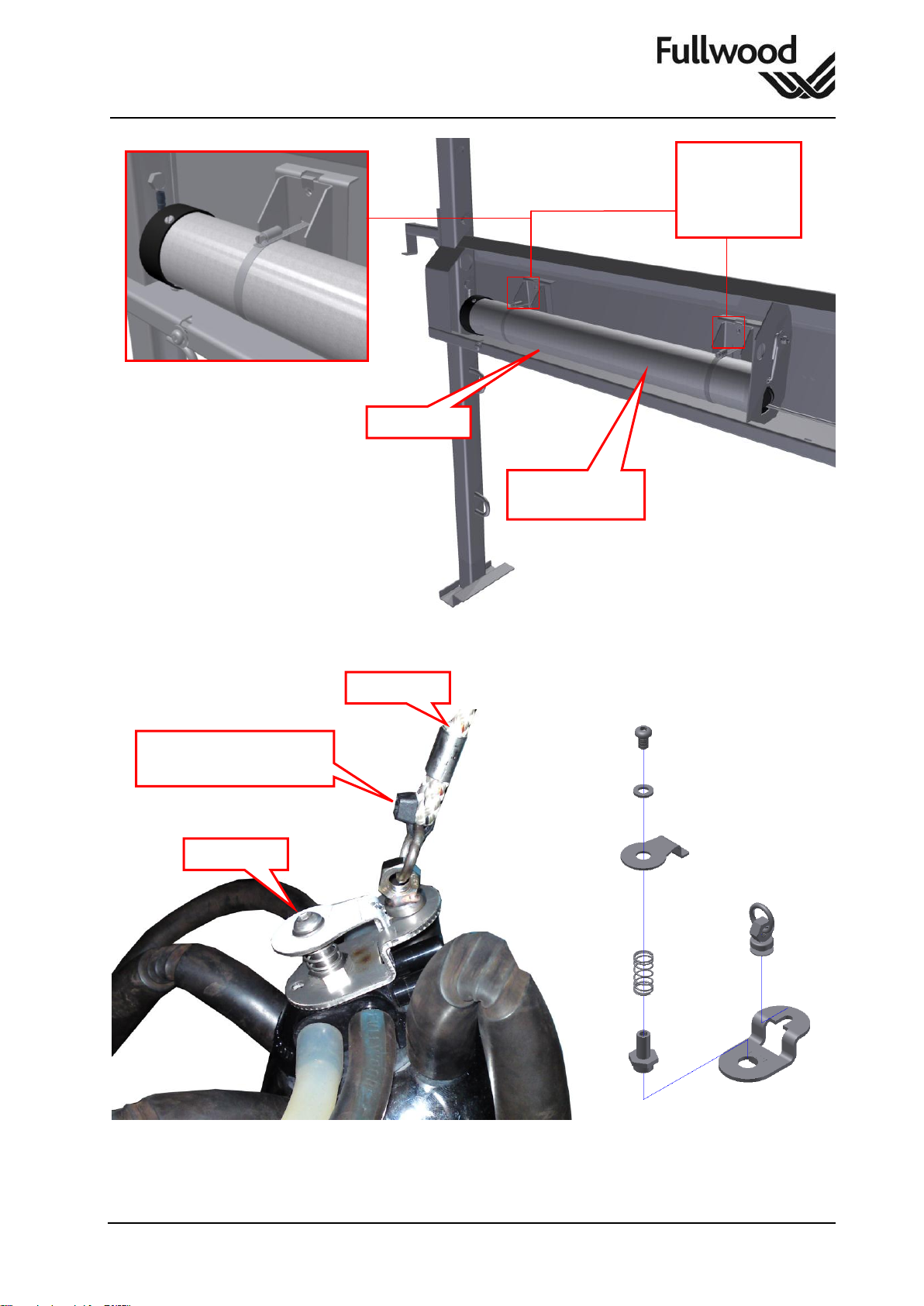
4. ACR Cylinders............................................................................... 7
4.1 SS ACR Cylinder................................................................................................7
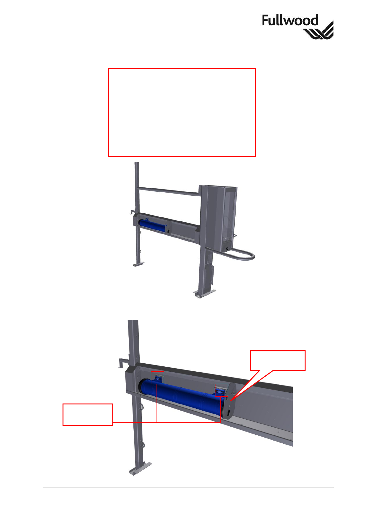
4.2 DVC 1000 ACR Cylinder....................................................................................9
5. Aflilite System Installation ......................................................... 11
6. Afiflo 2000 System Installation .................................................. 13
7. Milk Meter Installation................................................................. 15
7.1 AfiLite and Afiflow individual Gate Wiring Diagram...........................................15
7.2 AfiLite and Afiflow Fullstart Wiring Diagram......................................................16
7.3 Milk Meter Combination Fixing .........................................................................18
8. Milk Plate Variations................................................................... 21
9. Flip Down Jetter.......................................................................... 24
10. Fixed Jetter Installation.............................................................. 25
11. Arm Assembly Variations and Installation................................ 26
12. Milk and Pulsation Tube Fitting................................................. 27
13. Full Start System......................................................................... 28
14. Disclaimers.................................................................................. 29
Copyright © 2007, Fullwood Limited reserves the right to change the contents of this manual if
necessary, without warning. Fullwood Limited has taken every precaution to avoid errors and
omissions on the manual and equipment but does not accept any responsibility or liability for
damage of any kind arising from the use of this manual or Fullwood equipment; whether this
damage is direct or indirect. If you discover any inaccuracies please inform Fullwood Limited or
one of its agents and we will make corrections for the next release.

Ref / Pt.No: 006944
Revolution II Stage 3 Installation
Instruction
Revision: C
Date: 27-Nov-12
006944.doc Page 3 of 29
Important information - read this first
Before installing or operating the equipment, this manual and the appropriate operating
instructions must be read carefully.
The equipment must be used only for the application described.
Installation of the equipment must be carried out by skilled and authorized technicians
only.
Proper handling of the equipment is the basis for correct functioning.
Never remove any covers or parts off the system before the electrical power is
disconnected and isolated.
Do not wash the electronic equipment with volume washers or high pressure hoses.
It is the responsibility of the farmer to check his animals and the performance of the
equipment. If, for any reason, the system is not operational or individual animals refuse
to use the system, it is the responsibility of the farmer to make alternative arrangements
to feed and milk the animals.
To avoid injury to animals and equipment, check there are no projections (pipes or
anything similar) protruding in the parlour on which transponder neck bands or leg bands
can get caught.
Calibration of milk meters/monitors and feed dispensers are of utmost importance in
obtaining accurate milking and feeding results. If calibration is incorrect, or the wrong
values have been programmed, milking results and feed distribution will remain
adversely affected until calibration has been corrected.
The manufacturers guarantee does not cover direct or subsequent damage caused by
incorrect installation, incorrect usage, improper treatment, inadequate cleaning or
servicing, or incorrect software parameter inputs or hardware settings.
Incorrect operation of the milking or management system may seriously affect the
animals in an adverse way. It is therefore necessary to double check all inputs and
outputs of the system.
Icons
Icons are used in this manual to draw the reader’s attention to specific information. These icons
have the following meaning:
Failure to follow the instructions can result in severe injury to engineers, users,
bystanders or livestock.
Indicates special precautions that must be taken to avoid damage to equipment.
Gives important information to prevent potential problems.
Gives advice or suggestions to make procedures easier or clearer.

Ref / Pt.No: 006944
Revolution II Stage 3 Installation
Instruction
Revision: C
Date: 27-Nov-12
006944.doc Page 4 of 29
1. Safety
A risk assessment is an important step in protecting your workers and your business, as well as
complying with the law. It helps you focus on the risks that really matter in your workplace –the
ones with the potential to cause real harm. In many instances, straightforward measures can
readily control risks, for example ensuring spillages are cleaned up promptly so people do not
slip, or cupboard drawers are kept closed to ensure people do not trip. For most, that means
simple, cheap and effective measures to ensure your most valuable asset –your workforce –is
protected.
The law does not expect you to eliminate all risk, but you are required to protect people as far
as ‘reasonably practicable’.
There are many work situations which add to the hazards of welding. Each must be
assessed carefully, since there may be added hazards such as falls or asphyxiation.
This is particularly true of work in confined spaces, where there is a very real risk of
death, and the employer should make a critical assessment of the work to be done, and
how it may be carried out safely. There may be statutory requirements in these
situations.
Lifting and manual handling is one of the highest risks in work environments. It is
essential to inform your staff about safe lifting and manual handling basics.
Some form of dust extraction is also beneficial with heavy use as exposure to airborne
particles can cause respiratory complaints.
The main requirement of the PPE at Work Regulations 2002 is that personal protective
equipment is to be supplied and used at work wherever there are risks to health and
safety that cannot be adequately controlled in other ways.
Power tools can be extremely dangerous if not used correctly. The correct techniques
and personal protective equipment must be worn at all times.

Ref / Pt.No: 006944
Revolution II Stage 3 Installation
Instruction
Revision: C
Date: 27-Nov-12
006944.doc Page 5 of 29
2. Bail/Cabinet Part Numbers
Part Number
Description
MK3 Bail Assy S/S Tip
MK3 Bail S/Assy S/S Tip
Mk3 SS Lower Bail Post
187008
Mk3 Bail Assy m/s (Non Fdr)
187310
MK3 Bail Assy M/S+Feed
MK3 Bail S/Assy M/S+Feed
MK3 Bail Assy S/S Tip+Feed
MK3 Bail S/Assy S/S Tip+Feed
187577
MK3 Bail Assy SSTip&Leg+Feed
Mk3 Bail S/Assy SSTip+Fd-NoLeg
MK3 Bail Assy SSTip&Leg
Mk3 Bail S/Assy SSTip-NoLeg
Part Number
Description
190550
Standard Module Assy
190616
Standard Module with SS “D” Rail

Ref / Pt.No: 006944
Revolution II Stage 3 Installation
Instruction
Revision: C
Date: 27-Nov-12
006944.doc Page 6 of 29
3. Bail Assembly
3.1 Rope Guide Plate
186537 Rope Guide Plate Kit
1 x 190675 Ms Rope Guide Plate Assy
1 x 000424 M6x20 Hex Hd SS Screw
1 x 001622 M6 SS Washer
000424
001622
190675

Ref / Pt.No: 006944
Revolution II Stage 3 Installation
Instruction
Revision: C
Date: 27-Nov-12
006944.doc Page 7 of 29
4. ACR Cylinders
4.1 SS ACR Cylinder
186561 SS ACR Cyl Inst Kit
1 x 187223 MK3 Rotary SS Vac Cyl 675lg
2 x 187230 SS ACR Mount
2 x 100505 M6x20 SS Button Hd Socket Scw
2 x 001630 M6 SS Washer Form A
1 x 078490 QV Exhaust Valve for ACR Cyl
2 x 022001 Tube-8.7nb/150lg/17 od Rbr-U9.
1 x 190800 Clstr Breakaway Swivel Clip
1 x 106052 SS ACR Cyl Instruc Sht
2 x 003408 Rope Clip
2 x 089426 90-110 SS Jubilee Clip

Ref / Pt.No: 006944
Revolution II Stage 3 Installation
Instruction
Revision: C
Date: 27-Nov-12
006944.doc Page 8 of 29
When used with Cluster Support Arm the claw should be set to lift as high as possible, to
provide maximum clearance when travelling above the entrance bridge floor.
187223
2 x 187230
2 x 089426
2 x 100505
2 x 001630
Terminate
Rope Here
190800
003408
Cable Tie acts as the
breakaway device

Ref / Pt.No: 006944
Revolution II Stage 3 Installation
Instruction
Revision: C
Date: 27-Nov-12
006944.doc Page 9 of 29
4.2 DVC 1000 ACR Cylinder
106053 DVC 1000 ACR Cyl Instruc Sht
1 x 078060 DVC1000 ACR Cyl 90od Blue
2 x 000250 M6x25 SS Button Hd Socket Scw
2 x 001630 M6 SS Washer Form A
1 x 190800 Clstr Breakaway Swivel Clip
1 x 078490 QV Exhaust Valve for ACR Cyl
2 x 022001 Tube-8.7nb/150lg/17 od Rbr-U9.
2 x 003408 Rope Clip
Terminate
Rope Here
2 x 000250
2 x 001630

Ref / Pt.No: 006944
Revolution II Stage 3 Installation
Instruction
Revision: C
Date: 27-Nov-12
006944.doc Page 10 of 29
When used with Cluster Support Arm the claw should be set to lift as high as possible, to
provide maximum clearance when travelling above the entrance bridge floor.
190800
003408
Cable Tie acts as the
breakaway device

Ref / Pt.No: 006944
Revolution II Stage 3 Installation
Instruction
Revision: C
Date: 27-Nov-12
006944.doc Page 11 of 29
5. Aflilite System Installation
186558 Afilite M/M Inst Kit
6 x 100506 Z4x5/16 Pan S/T Screw-Ab-ss
2 x 000432 M6x30mm Lg SS Hex Hd S/Screw
2 x 001158 M6 SS Nyloc Nut
4 x 001630 M6 SS Washer Form A
1 x 133557 Silicone Rbr Reducing Elbow
2 x 003518 Straight Hose Con Ges8r1/8
Afilite
190638
6 x 100506

Ref / Pt.No: 006944
Revolution II Stage 3 Installation
Instruction
Revision: C
Date: 27-Nov-12
006944.doc Page 12 of 29
186557 Afilite Galv Door Inst Kit
1 x 190638 MK2 Afilite Galv Door Assy
1 x 190677 Mk2 Rotary Rope Guide Rail Kit
1 x 000424 M6x20 Hex Hd SS Screw
1 x 001622 M6 SS Washer Form C
1 x 190622 Mk2 M/S Upper Door
1 x 190583 Module Lid Assy
2 x 000447 M6x16 Hex Hd SS Setscrew
2 x 001626 M6 SS Penny Washer
2 x 000447
2 x 001626
190677
190583
190622
190638
000424
001622

Ref / Pt.No: 006944
Revolution II Stage 3 Installation
Instruction
Revision: C
Date: 27-Nov-12
006944.doc Page 13 of 29
6. Afiflo 2000 System Installation
186566 Afiflo 2000 M/M Inst Kit
1 x 133506 Plastic Adpt Moulding
2 x 190558 MK2 Afiflo Door Strap
4 x 000423 M6x25 Hex Hd SS Screw
4 x 001622 M6 SS Washer Form C
2 x 000432 M6x30mm Lg SS Hex Hd S/Screw
2 x 001158 M6 SS Nyloc Nut
4 x 001630 M6 SS Washer Form A
1 x 133557 Silicone Rbr Reducing Elbow
2 x 003518 Straight Hose Con Ges8r1/8
1 x 006625 Afiflo 2000 User Manual
10 x 005110 Cable Tie Nylon Black300x4.8mm
Assemble the Afiflo before placing it into the Bail.
190555
133506
190558
4 x 000423
4 x 001622
Afiflo

Ref / Pt.No: 006944
Revolution II Stage 3 Installation
Instruction
Revision: C
Date: 27-Nov-12
006944.doc Page 14 of 29
186565 Afiflo 2000 Galv Door Inst Kit
1 x 190555 Mk2 Afiflo Door Assy(Galv)
1 x 190677 Mk2 Rotary Rope Guide Rail Kit
1 x 000424 M6x20 Hex Hd SS Screw
1 x 001622 M6 SS Washer Form C
1 x 190622 Mk2 M/S Upper Door
1 x 190583 Module Lid Assy
2 x 000447 M6x16 Hex Hd SS Setscrew
2 x 001626 M6 SS Penny Washer
190583
190622
2 x 000447
2 x 001626
190677
190555
000424
001622

Ref / Pt.No: 006944
Revolution II Stage 3 Installation
Instruction
Revision: C
Date: 27-Nov-12
006944.doc Page 15 of 29
7. Milk Meter Installation
7.1 AfiLite and Afiflow individual Gate Wiring Diagram

Ref / Pt.No: 006944
Revolution II Stage 3 Installation
Instruction
Revision: C
Date: 27-Nov-12
006944.doc Page 16 of 29
7.2 AfiLite and Afiflow Fullstart Wiring Diagram

Ref / Pt.No: 006944
Revolution II Stage 3 Installation
Instruction
Revision: C
Date: 27-Nov-12
006944.doc Page 17 of 29
186563 Rotary M/M Wiring Conn Kit
1 x 097185 R/A MM Connection Kit
2 x 000398 M5x20 Teks Self Drill Screw
2 x 001634 M5 Penny Washer SS
6 x 005164 Yellow Ferrule(1.0mmSQ)
1 x 005105 Terminal Block 12Way 5A PVC
6 x 005792 Red 1.5mm Pre-Isul Seald Splcs
10 x 005110 Cable Tie Nylon Black300x4.8mm
000689
001634

Ref / Pt.No: 006944
Revolution II Stage 3 Installation
Instruction
Revision: C
Date: 27-Nov-12
006944.doc Page 18 of 29
7.3 Milk Meter Combination Fixing
186560 M/M Combination Brkt Kit
1 x 187038 Meter Combination Brkt
2 x 000486 M10x20 Hex Hd SS Setscrew
2 x 001153 M10 SS Nyloc Nut
2 x 001676 M10x2 Thk(21od)SS Washer
186558/186556 Afilite/Afiflo M/M Inst Kit
6 x 100506 Z4x5/16 Pan S/T Screw-Ab-ss
2 x 000432 M6x30mm Lg SS Hex Hd S/Screw
2 x 001158 M6 SS Nyloc Nut
4 x 001630 M6 SS Washer Form A
1 x 133557 Silicone Rbr Reducing Elbow
2 x 003518 Straight Hose Con Ges8r1/8
187038
000486
001153
001676
Clockwise Fixing
Position
Anti- Clockwise
Fixing Position

Ref / Pt.No: 006944
Revolution II Stage 3 Installation
Instruction
Revision: C
Date: 27-Nov-12
006944.doc Page 19 of 29
186559 M/M Legato&Dry Air Inst Kit
1 x 142901 Legato Life 24V 4pQM Less Cabl
1 x 142911 Legato Cable 4pole 1x4core 5m
1 x 042941 Legato QM Clean Air Kit
1 x 035515 Vac Clamp Valve Assy
1 x 000273 3/8BSWx3/4"Hex Hd SS S/Scrw
000432
001158
001630
000273
Anti- Clockwise
Fixing Position
Clockwise Fixing
Position

Ref / Pt.No: 006944
Revolution II Stage 3 Installation
Instruction
Revision: C
Date: 27-Nov-12
006944.doc Page 20 of 29
Drill a 27mm hole in the Dry Vacuum Line, secure the valve clamp assembly over it. The
installation guide of the vacuum line can be found in the stage 4 manual.
035515
Table of contents
Other Fullwood Farm Equipment manuals