MicroNet SP373HS User manual

User’s Manual
10/100TX to 100FX Industrial Media Converter
Model No.: SP373HS
World Wide Web: www.micronet.com.tw ; www.micronet.info

FCC Warning
This Equipment has been tested and found to comply with the limits for a
Class A digital device, pursuant to Part 15 of the FCC rules. These limits
are designed to provide reasonable protection against harmful
interference in a residential installation. This equipment generates, uses,
and can radiate radio frequency energy. It may cause harmful interference
to radio communications if the equipment is not installed and used in
accordance with the instructions. However, there is no guarantee that
interference will not occur in a particular installation. If this equipment
does cause harmful interference to radio or television reception, which can
be determined by turning the equipment off and on, the user is
encouraged to try to correct the interference by one or more of the
following measures:
Reorient or relocate the receiving antenna.
Increase the separation between the equipment and receiver.
Connect the equipment into an outlet on a circuit different from that to
which the receiver is connected.
Consult the dealer or an experienced radio/TV technician for help.
CE Mark Warning
This is a class A product. In a domestic environment this product may
cause radio interference in which case the user may be required to take
adequate measures.

Content
FCC Warning.......................................................i
CE Mark Warning................................................i
Overview.............................................................1
Introduction ..............................................................1
Features...................................................................3
Packing List.............................................................. 4
Safety Precaution..................................................... 4
Hardware Description.........................................5
Front Panel............................................................... 5
Top View..................................................................6
Wiring the Power Inputs...........................................6
Wiring the Fault Alarm Contact................................ 7
LED Indicators..........................................................7
DIP-Switch ...............................................................8
Ports.........................................................................9
Cabling...................................................................11
Mounting Installation ........................................12

DIN-Rail Mounting.................................................. 12
Wall Mount Plate Mounting....................................14
Network Connection.........................................15
Installation Steps.................................................... 15
Troubles shooting.............................................17
Technical Specification.....................................18

Overview
Introduction
The SP373HS Industrial 10/100Base TX to 100BaseFX Media
Converter is a cost-effective solution for the converting between
10/100Base-TX and 100Base-FX cabling, it allows you to extend the
cabling distance of your 100Base-FX network up to 30 kilometers for
single-mode fiber (SC connector).
Fast Fiber Converters Module
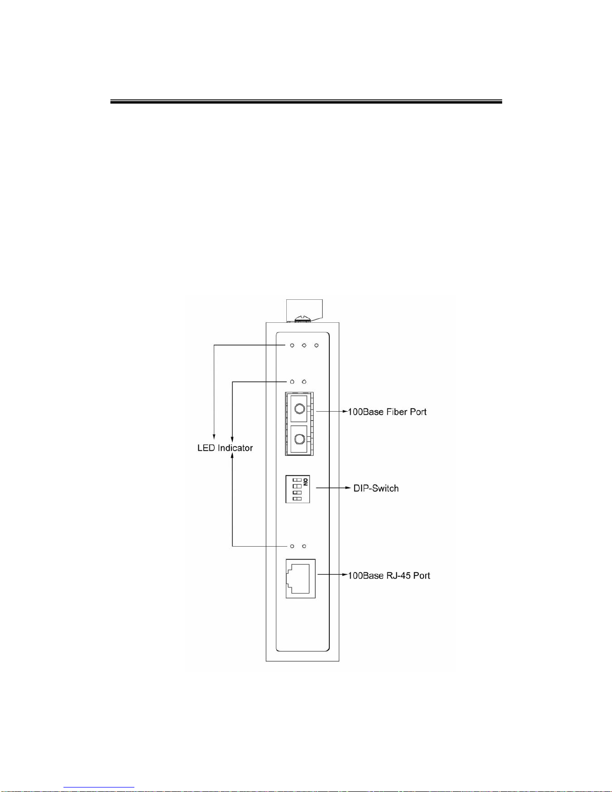
The Industrial 10/100Base TX to 100BaseFX Media Converter provides
you with one Fiber connector for your fiber optic cable and one Ethernet
RJ-45 port (Auto MDI/MDIX) for your 100Base-TX copper cable
connection. There are four DIP-switches to set the operation mode for
UTP, Fiber ports and link loss forwarding function.
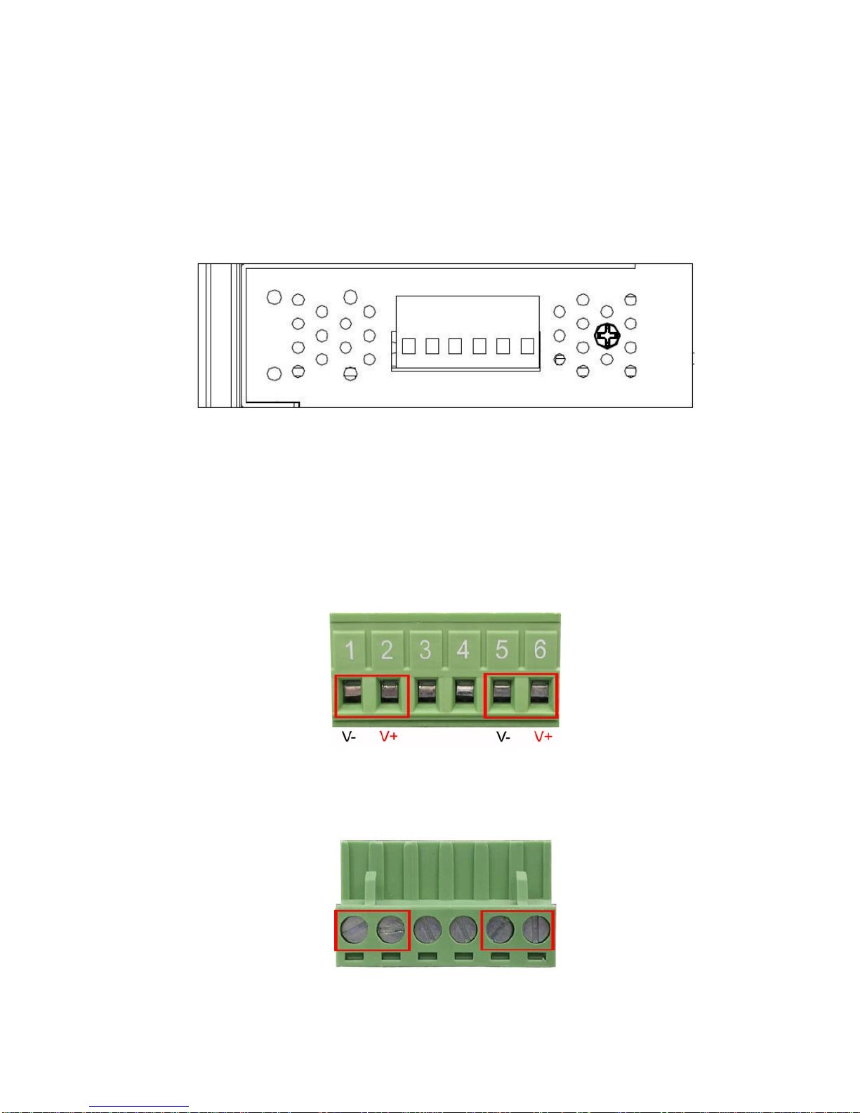
Dual Power Input
To reduce the risk of power failure, the Industrial 10/100Base TX to
100BaseFX Media Converter provides +12 ~ 48 VDC dual power inputs.
If there is power failure, Industrial 10/100Base TX to 100BaseFX Media
Converter will automatically switch to the secondary power input.
Flexible Mounting
Industrial 10/100Base TX to 100BaseFX Media Converter is extremely
compact and can be mounted on a DIN-rail or a panel, so it is suitable
for any space-constrained environment.
Advanced Protection
The power line of Industrial 10/100Base TX to 100BaseFX Media
Converter supports up to 3,000 VDC EFT protection, which secure
equipment against unregulated voltage and make systems safer and
more reliable. Meanwhile, 6,000 VDC ESD protections for Ethernet ports
make Industrial 10/100Base TX to 100BaseFX Media Converter more
suitable for harsh environments.
1

Wide Operating Temperature
The operating temperature of the Industrial 10/100Base TX to
100BaseFX Media Converter is between -40 ~ 75oC (wide operating
temperature model) or -10 ~ 60oC (standard model). With such a wide
range, you can use the Industrial 10/100Base TX to 100BaseFX Media
Converter in some of the harshest industrial environments that exist.
Easy Troubleshooting
LED indicators make troubleshooting quick and easy. The 10/100
Base-TX port has 2 LEDs that display the link status, transmission
speed and collision status. Also the three power indicators P1, P2 and
Fault help you diagnose immediately.
2

Features
Provides 1 x 10/100Mbps Ethernet ports with RJ-45 connector
IEEE802.3x Flow Control and Back pressure
Provides 1 x SC (single-mode) fiber connector
Supports full/half duplex flow control
Supports MDI/MDI-X auto-crossover
Supports surge (EFT) protection 3,000 VDC for power line
Supports 6,000 VDC Ethernet ESD protection
Supports auto-negotiation
Supports store & forward transmission
Supports redundant +12 ~ 48 VDC power with polarity reverse protect
function and removable terminal block removable terminal block
Provides flexible mounting: DIN-rail, Wall Mounting
Supports IP-30 Protection
Built-in Link Lose Forwarding (LLF) & Link Fault Pass-Through(LFP)
Technology
Supports operating temperatures from -40 to 75oC (wide operating
temperature)
Overload Current Re-settable Fuse Present
Power Polarity Reverse Protect
3

Packing List
1 x Industrial 10/100BaseTX to 100BaseFX Media Converter
1 x User manual
2 x Wall Mounting Bracket and Screws
1 x DIN-rail Mounting Bracket and Screws
Safety Precaution
Attention IF DC voltage is supplied by an external circuit, please use a
protection device on the power supply input.
4

Hardware Description
In this chapter, you will be given an overview of the Industrial
10/100Base TX to 100BaseFX Media Converter hardware installation
procedures.
Front Panel
The Front Panel of the Industrial 10/100Base TX to 100BaseFX Media
Converter is shown as follows.
Front Panel of SP373HS 10/100TX to 100FX Industrial Media Converter
5

Top View
The top panel of the Industrial 10/100Base TX to 100BaseFX Media
Converter is equipped one terminal block connector of two DC power
inputs.
Top Panel of SP373HS 10/100Base TX to 100BaseFX Industrial Media Converter
Wiring the Power Inputs
Please follow the steps below to insert the power wire.
Insert the positive and negative wires into the V+ and V- contacts on the
terminal block connector.
Tighten the wire-clamp screws for preventing the wires from loosing.
6

Wiring the Fault Alarm Contact
The fault alarm contact is in the middle of terminal block connector as the
picture shows below. Inserting the wires, it will detect the fault status
including power failure/port link failure and form an open circuit.
Insert the wires into the fault alarm contact.
Note The wire gauge for the terminal block should be in the range
between 12~ 24 AWG.
LED Indicators
There are few LEDs, which display the power status and network status,
located on the front panel of the Industrial 10/100Base TX to
100BaseFX Media Converter, each of them has its own specific
meaning as below table.
LED Color Description
On Power input 1 is active
P1 Green
Off Power input 1 is inactive
On Power input 2 is active
P2 Green
Off Power input 2 is inactive
On Power input 1 or 2 has failed
Fault Red
Off Power input 1 and 2 are both functional, or no
power inputs
7

On Full-duplex mode
Flashing Packet collision occurred
FDX/COL
(fiber port) Amber
Off Half-duplex mode
On Connected to network
Flashing Networking is active
LNK/ACT
(fiber port) Green
Off Not connected to network
On Link to 100Mbps network
100M (RJ-45) Amber Off Link to 10Mbps network
On Connected to network
Flashing Networking is active
LNK/ACT
(RJ-45) Green
Off Not connected to network
DIP-Switch
The DIP-Switch is used to configure operation mode for LLF (Link Lose
Forwarding) and operation mode for UTP/Fiber port. The default value
of DIP-switch is OFF.
S/W No Status Description
ON Enables Port/Power Alarm
1 OFF Disable Port/Power Alarm
ON Enables LLF
2 OFF Disables LLF
ON 100Base-FX Half-mode
3 OFF 100Base-FX Full-mode
ON Media mode (100TX to 100FX)
4 OFF Switching mode
Link Lose Forwarding (DIP-Switch 2): When LLF enabled, it allows
UTP link failures to be reported to the fiber side and also allows Fiber
link failures to be reported to the UTP side. Therefore, a link fault
pass-through feature is provided in both UTP and Fiber side.
Media mode (DIP-Switch 4): When media mode is enabled (ON), it
operates with the minimum latency. The transmission flow does not wait
until entire frame is ready, but instead it forwards the received data
8

immediately after the data being received. And TP port should be forced
at 100M in this application. When DIP-Switch is in switching mode
(OFF), the converter function is the same as a Switch Hub.
Note Please don’t change the DIP-switch setting when UTP or fiber port
is transmitting or receiving data. It may cause some data error.
Besides, if you change the DIP-switch setting, please power off
the converter and power on again to make the setting effective.
Ports
RJ-45 ports (Auto MDI/MDIX): The RJ-45 ports are auto-sensing for
10Base-T or 100Base-TX devices connections. Auto MDI/MDIX means
that you can connect to another switch or workstation without changing
straight through or crossover cabling. See figures as below for straight
through and crossover cable schematic.
RJ-45 Pin Assignments
Pin Number Assignment
1 Tx+
2 Tx-
3 Rx+
6 Rx-
Note “+” and “-” signs represent the polarity of the wires that make up
each wire pair.
All ports on this unit support automatic MDI/MDI-X operation, you can
use straight-through cables (See Figure below) for all network
connections to PCs or servers, or to other switches or hubs. In
straight-through cable, pins 1, 2, 3, and 6, at one end of the cable, are
connected straight through to pins 1, 2, 3 and 6 at the other end of the
cable. The table below shows the 10BASE-T/ 100BASE-TX MDI and
MDI-X port pin outs.
9

Pin MDI-X Signal Name MDI Signal Name
1 Receive Data plus (RD+) Transmit Data plus (TD+)
2 Receive Data minus (RD-) Transmit Data minus (TD-)
3 Transmit Data plus (TD+) Receive Data plus (RD+)
6 Transmit Data minus (TD-) Receive Data minus (RD-)
Straight Through Cable Schematic
Cross Over Cable Schematic
Fiber Port
The fiber port of SC type connector can work in single mode (30Km).
When you connect the fiber port to another one, please follow the figure
below to connect accordingly. Wrong connection will cause the port
cannot work normally.
10

ATTENTION This is a Class 1 Laser/LED product. Don’t stare into
the Laser/LED Beam.
Cabling
Twisted-pair segment can be connected with unshielded twisted pair (UTP)
or shielded twisted pair (STP) cable. The cable must comply with the IEEE
802.3u 100Base TX standard for Category 5. The cable between the
converter and the link partner (converter, switch, hub, workstation, etc.)
must be less than 100 meters (328 ft.) long.
Fiber segment using single-mode connector type must use 9/125µm
single-mode fiber cable. User can connect two devices in the distance up
to 30 Kilometers.
11

Mounting Installation
DIN-Rail Mounting
The DIN-Rail is screwed on the unit when out of factory. If the DIN-Rail is
not screwed on the unit, please see the pictures and follow the steps
below to screw the DIN-Rail on the unit.
1. Use the screws to screw the DIN-Rail on the rear side of the unit.
2. To remove the DIN-Rail, reverse the step 1.
12

3. After the DIN-Rail is screwed on the rear side of the unit, insert the
top of DIN-Rail into the track.
4. Then, lightly push the DIN-Rail into the track.
5. Check if the DIN-Rail is tightened on the track or not.
6. To remove the unit from the track, reverse steps above.
13

Wall Mount Plate Mounting
Follow the steps below to mount the unit with wall mount plate.
1. Remove the DIN-Rail from the unit; loose the screws to remove the
DIN-Rail.
2. Place the wall mount plate on the top & bottom side of the unit.
3. Use the screws to screw the wall mount plate on the unit.
4. Use the hook holes at the corners of the wall mount plate to hang the unit
on the wall.
5. To remove the wall mount plate, reverse steps above.
14

Network Connection
In this paragraph, we will describe how to install the Industrial 10/100Base TX
to 100BaseFX Media Converter.
Installation Steps
1. Unpack the unit packing.
2. Check the DIN-Rail is screwed on the unit. If the DIN-Rail is not screwed
on the unit. Please refer to DIN-Rail Mounting section for DIN-Rail
installation. If you want to wall mount the unit, then please refer to Wall
Mount Plate Mounting section for wall mount plate installation.
15

3. To hang the unit on the DIN-Rail track or wall, please refer to the
Mounting Installation section.
4. Power on the Unit. How to wire the power; please refer to the Wiring the
Power Inputs section. The power LED on the unit will light up. Please
refer to the LED Indicators section for meaning of LED lights.
5. Prepare the twisted-pair, straight through Category 5 cable for Ethernet
connection.
6. Insert one side of Category 5 cables into the Ethernet port (RJ-45 port)
and another side of category 5 cables to the network devices’ Ethernet
port (RJ-45 port), ex: switch, PC, or Server. The UTP port (RJ-45) LED on
the unit will light up when the cable connected with the network device.
Please refer to the LED Indicators section for LED light meaning.
7. Connect one end of the fiber cable to the SC single-mode connector on
this converter and the other end of the fiber cable to the SC single-mode
connector on the other 100 Base-FX devices.
Note Be sure the connected network devices support MDI/MDI-X. If it
does not support, then use the crossover category 5 cable.
8. When all connections are all set and LED lights all show in normal, the
installation is complete.
16
Table of contents
Other MicroNet Media Converter manuals
Popular Media Converter manuals by other brands

SRS Lighting
SRS Lighting DST4H-3 instruction manual

Feig Electronic
Feig Electronic OBID i-scan ID ISC.ANT.PS-B Installation

PRO SIGNAL
PRO SIGNAL PSG3448 quick start guide

Lindy
Lindy 41006 user manual

Danfoss
Danfoss VLT AutomationDrive FC 301 operating instructions

Manhattan
Manhattan 179225 Quick install guide

evertz
evertz 570REM-TX8-10GE user manual

Transition Networks
Transition Networks SPSVT26xx-100 user guide

Baxall
Baxall IP-ENC1-R installation instructions

Edimax
Edimax ET-940MCR user manual

CEntrance
CEntrance DACmini CX user manual

Absolute Process Instruments
Absolute Process Instruments DuoPak APD 2031 manual