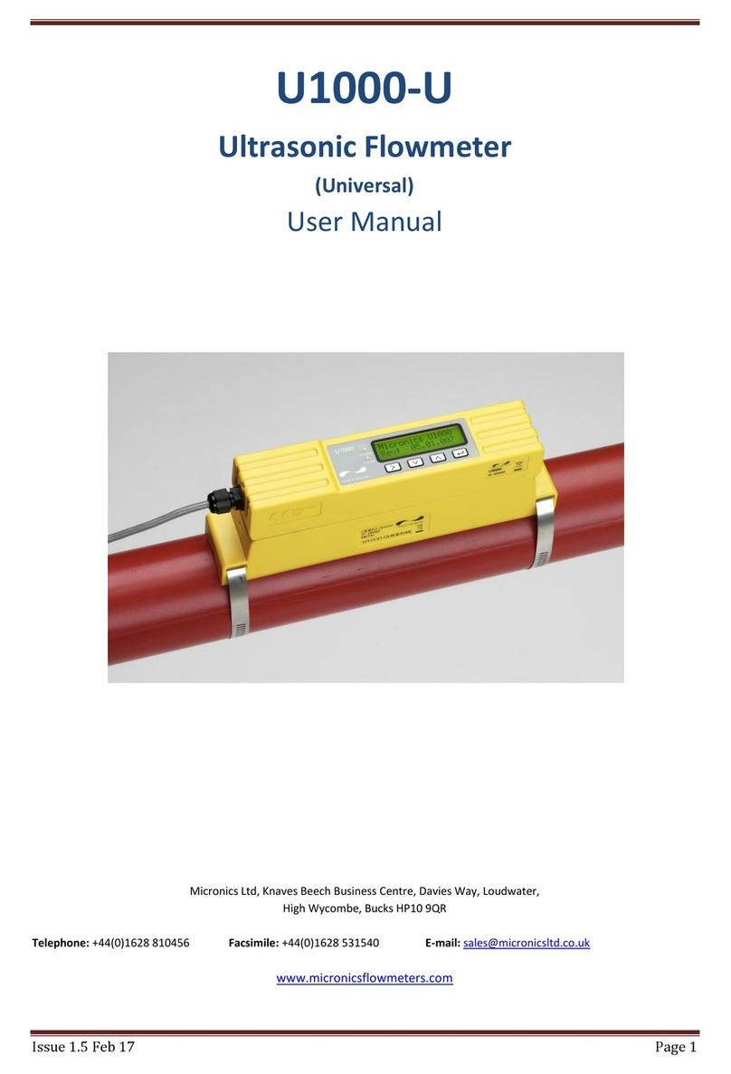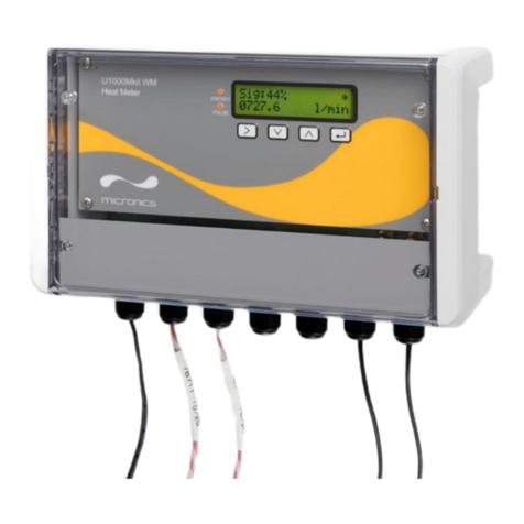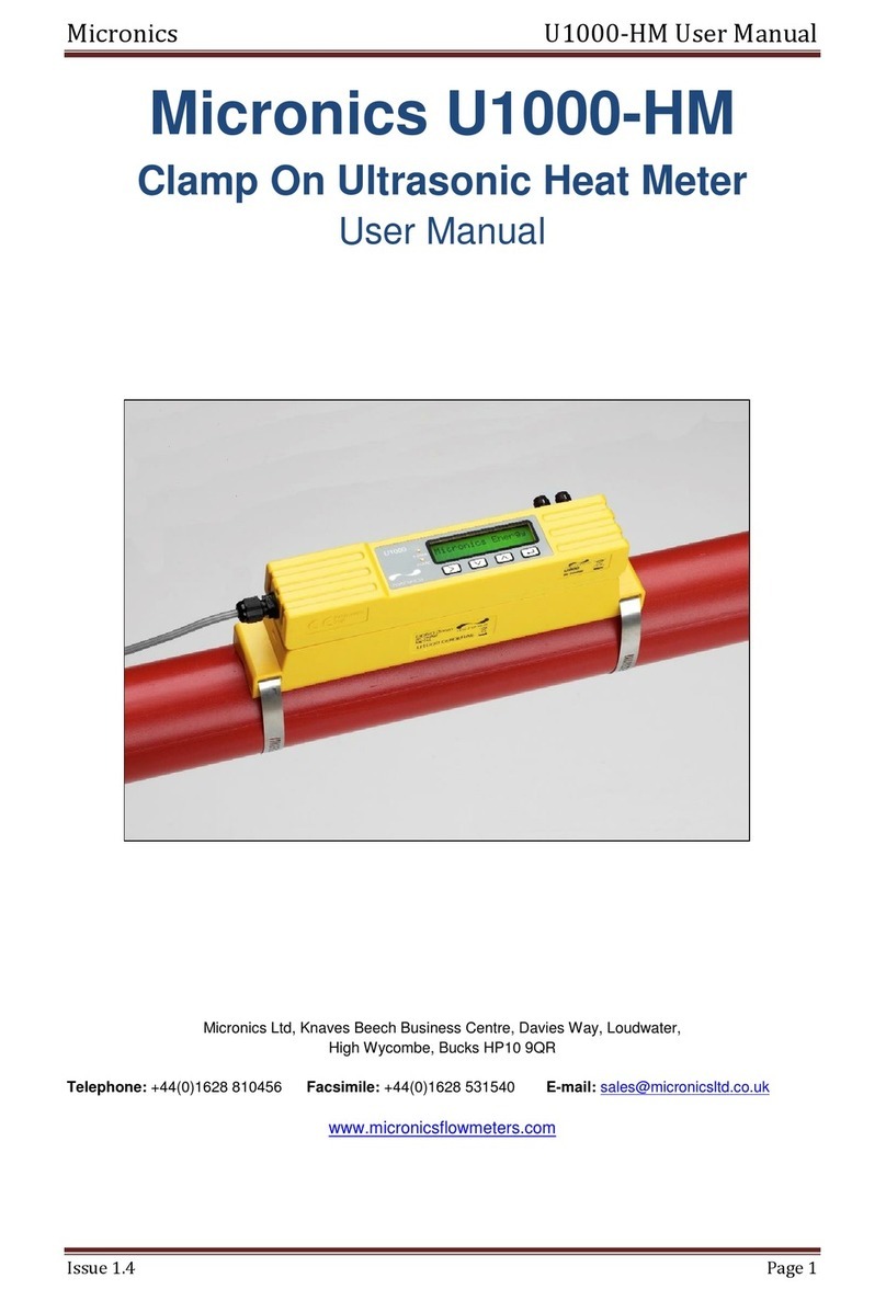
Micronics U1000-HM User Manual
Issue 2.5 July 17
Page 2
Table of Contents
1General Description..................................................................................................................................... 3
2Quick Start Procedure ................................................................................................................................. 4
3How Does It Work?...................................................................................................................................... 5
4User Interface .............................................................................................................................................. 6
4.1 Key Switches ....................................................................................................................................... 6
5Installing The U1000-HM............................................................................................................................. 7
5.1 Preparation .......................................................................................................................................... 8
5.2 Sensor Separation............................................................................................................................... 8
5.3 Attaching The U1000-HM To The Pipe ............................................................................................. 10
5.4 Adaptors For Small Pipes.................................................................................................................. 11
5.5 Attaching The Temperature Sensors................................................................................................. 12
5.6 U1000-HM Interface Cables.............................................................................................................. 13
5.7 Connecting The U1000-HM To The Supply ...................................................................................... 13
5.8 Pulse Output Connection................................................................................................................... 15
5.9 Modbus Connections......................................................................................................................... 15
5.10 Cable Screen..................................................................................................................................... 15
6Powering Up For The First Time ............................................................................................................... 16
6.1 How To Enter The Pipe ID................................................................................................................. 18
6.2 Pulse Output...................................................................................................................................... 19
6.2.1 Volumetric Mode........................................................................................................................ 19
6.2.2 Frequency Mode........................................................................................................................ 19
6.2.3 Energy Mode ............................................................................................................................. 19
6.2.4 Low Flow Alarm ......................................................................................................................... 19
6.3 Modbus.............................................................................................................................................. 20
6.4 Information Screens........................................................................................................................... 22
7Password Controlled Menus...................................................................................................................... 23
7.1 General Procedure For Changing Menu Settings ............................................................................. 23
7.1.1 Selection Menus ........................................................................................................................ 23
7.1.2 Data Entry Menus...................................................................................................................... 23
7.2 User Password Controlled Menu Structure ....................................................................................... 23
8Diagnostics Menu ...................................................................................................................................... 29
9Relocation Of Guide Rail........................................................................................................................... 30
10 Appendix I –U1000-HM Specification................................................................................................... 31
11 Appendix II –Default Values ................................................................................................................. 33
12 Appendix III –Error And Warning Messages ........................................................................................ 34
13 Declaration of conformity ………………………….……………………………………………...……………..36
