Micronics Ultraflo 2000 User manual
Other Micronics Measuring Instrument manuals
Micronics
Micronics Portaflow 222 User manual
Micronics
Micronics Ultraflo 2000 User manual
Micronics
Micronics Portaflow 333HM User manual
Micronics
Micronics UF D5500 User manual

Micronics
Micronics U3000 User manual
Micronics
Micronics U1000-HM User manual
Micronics
Micronics U1000MKII-HM User manual
Micronics
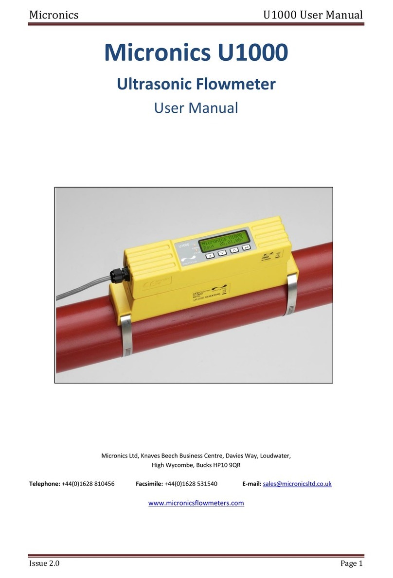
Micronics PF D550 Installation instructions
Micronics
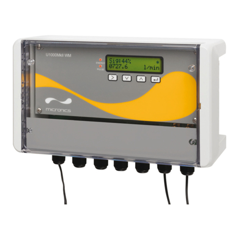
Micronics U1000 User manual
Micronics
Micronics U1000MkII WM User manual

Micronics
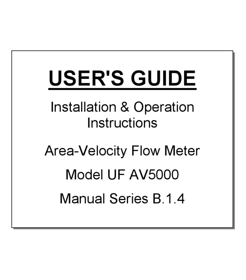
Micronics U1000MkII WM User manual
Micronics
Micronics UF AV5000 Installation instructions
Micronics
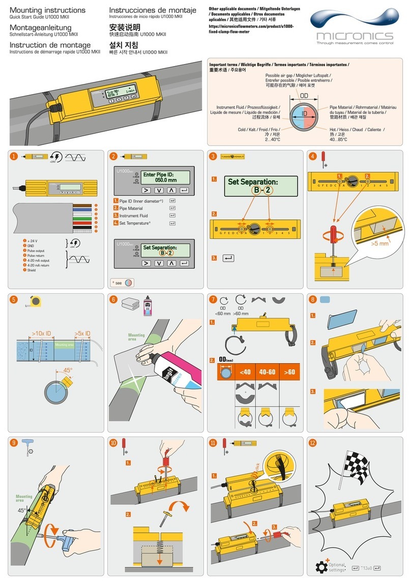
Micronics portaflow 220 User manual
Micronics
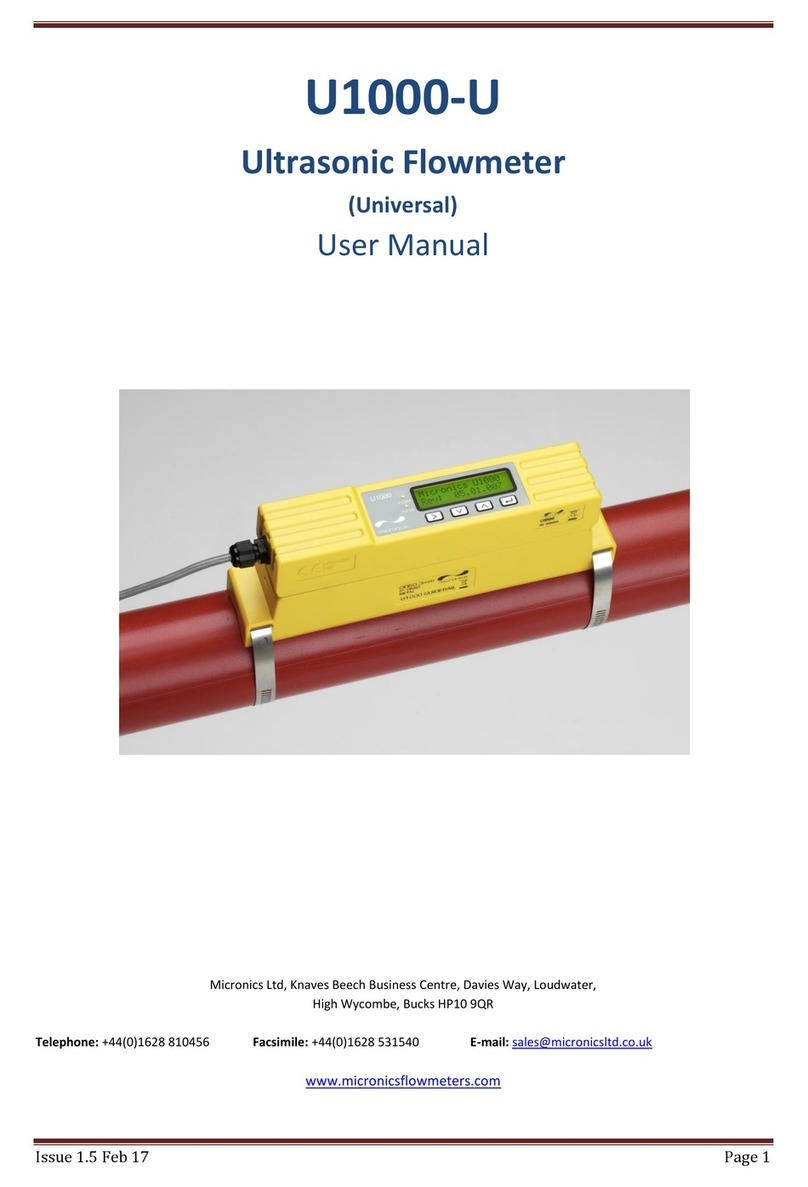
Micronics U1000 User manual
Micronics
Micronics U1000-U User manual

Micronics
Micronics PORTAFLOW 300 User manual

Micronics
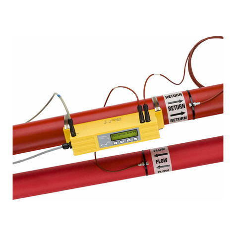
Micronics U1000MKII-HM User manual
Micronics
Micronics U1000MKII-FM User manual

Micronics
Micronics Portaflow 222 User manual

Micronics
Micronics U1000-HM User manual
Popular Measuring Instrument manuals by other brands

Powerfix Profi
Powerfix Profi 278296 Operation and safety notes

Test Equipment Depot
Test Equipment Depot GVT-427B user manual

Fieldpiece
Fieldpiece ACH Operator's manual

FLYSURFER
FLYSURFER VIRON3 user manual

GMW
GMW TG uni 1 operating manual

Downeaster
Downeaster Wind & Weather Medallion Series instruction manual

Hanna Instruments
Hanna Instruments HI96725C instruction manual

Nokeval
Nokeval KMR260 quick guide

HOKUYO AUTOMATIC
HOKUYO AUTOMATIC UBG-05LN instruction manual

Fluke
Fluke 96000 Series Operator's manual

Test Products International
Test Products International SP565 user manual

General Sleep
General Sleep Zmachine Insight+ DT-200 Service manual

