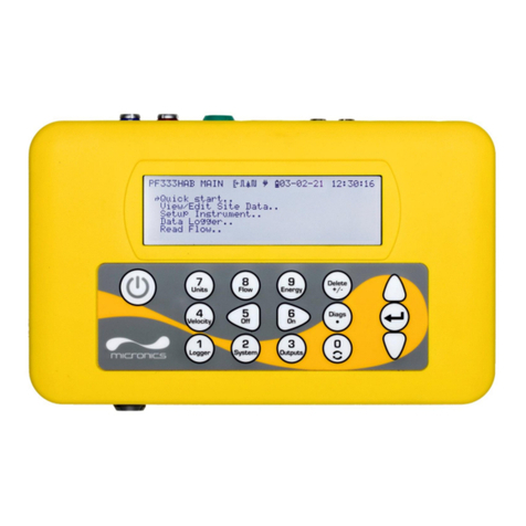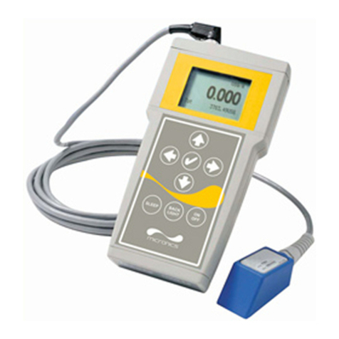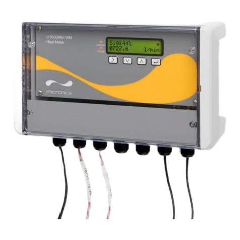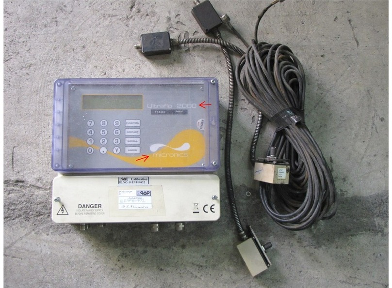
ULTRAFLO 2000 INSTALLATION & OPERATING INSTRUCTIONS
4
INTRODUCTION
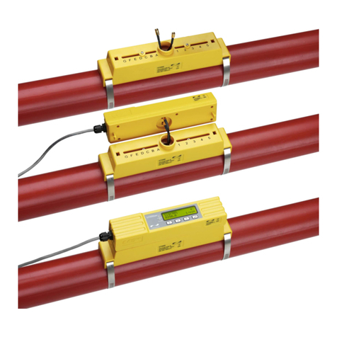
The Ultraflo 2000 is a “Clamp-on” liquid flow meter
that uses the Transit Time method of
measurement to read flow. Using two PT100
temperature probes to measure temperature it
can also be used as a Heat/Energy meter.
The Ultraflo is able to measure the flow of liquid in
any pipe from 13mm to 5000mm, providing the
pipe is flooded and the correct transducers are
used. Units are supplied according to application
data provided by the customer.
The instrument displays volumetric flow rate in
m3/hr, m3/min, m3/sec, g/min, USg/hr, l/min, l/sec
and linear velocity in metres and feet per second.
The total volume of flow will be displayed, up to a
maximum 12-digit number. When supplied as a
Heatmeter, kW, kCal/hr, MJ/hr, MJ/min and
MJ/sec can be displayed, as well as the
temperature differential.
The flowmeter is supplied with electronics,
sensors and all mounting hardware. The
Heatmeter version will also be supplied with
PT100 temperature probes.
HARDWARE
Electronics Housing
An ABS housing with an opaque door contains the
master PCB. The housing is designed for wall
mounting using the brackets provided (see Figure
2 for mounting pattern). Drilling further fixing holes
in the Housing remove the IP67 protection rating
and CE approval.
Mounting the housing into position does not
require the removal of the electronics or the front
display panel.
Figure 2
DO NOT PROVIDE POWER to the instrument
until the service compartment cover has been
replaced.
The electronics are factory set for a particular
supply voltage. Should it be necessary to change
the settings for the power supply see page 7,
Power up.
Having completed the procedure for mounting the
electronics, connecting all cables and checking
the power supply, the power can now be applied.
The Ultraflo 2000 is now ready for programming.
A full programming procedure is described on
page 7.
Before programming the instrument, it is
necessary to attach the transducers to the pipe
wall such that they can be finally locked in the
correct position based on exact data provided by
the instrument.
TRANSDUCERS
Each instrument uses two identical transducers,
which transmit and receive the ultrasonic waves.
They are clamped to the pipe surface using the
mounting hardware supplied, as described on
pages 5, 6.
The standard transducers are made from a Peek
material with an aluminium plate supporting the
stud, used to lock the sensor in position. A flying
armoured lead is attached between the sensor
block and the tuning circuit.
Figure 3 – 1MHz Sensors with TNC Coaxial
Connector
Transducers are supplied according to the pipe
size and flow velocity, and are available to meet
an operating temperature range from –20°C up to
+200°C.
Transducer Connections
Transducers are connected to the electronics from
the tuning circuit by TNC connectors. All other
output and input connections are made through
metal glands to the clearly marked terminals.
Only one current output can be used with the flow
meter, but both can be used when the Heatmeter
option is supplied. Connections 5-10 can only be
used when the PT100 temperature probes are
supplied with the Heatmeter.
1 2 3 4 5 6 7 8 9 10 11 12 13 14 15 16 17 18
+ - + - + - + + - + NC COM NO + L N E
MA1 MA2 HOT COLD RELAY 24VDC AC IN
F
S
Coax sensor connectors
Coax cable
220VAC
24V
110VAC
F

