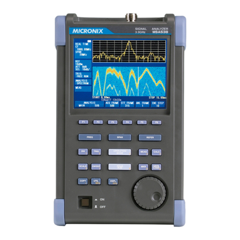
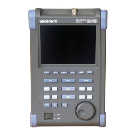
Micronix MSA538 User manual

Ver.1.09 / Nov. / 2016
MICRONIX CORPORATION
3.3GHz/8.5GHz Handheld Signal Analyzer
MSA538(E/TG)/MSA558(E)
Operating manual
OM-12014

–I–
Before Using the Product
· Please use following the below notes described on the back panel.
· For safe use
1) When abnormal sound, abnormal smell or smoke is found, stop using and remove the battery and AC
adapter.
2) Never use this product by wet hands, or the electric shock, a fire or the damage is caused.
3) Never use this product when thundering, or the damage by lightning may be caused.
4) Never use any AC adapter other than specified, or the damage is caused. And connect the power cable to
three-terminal outlet for protecting from static electricity, or this product or a device under test may be
damaged.
5) Never use any battery other than specified, or this product is damaged. When removing or installing the
battery, do it after turning off the power and disconnecting AC adapter.
6) Be sure to charge the battery by the specified way.
Moreover, an explosion, a fire or smoking may happen if the handling of the battery is improper.
Please read the notes of the handling of battery.
· Set clock function
The time information is set at Japan standard time. Set the year, month, day and time when MSA500 series is
used for the first time. (Refer to “24.4 Setting of clock” for the details.)

–II–
· Quality assurance
Warranty
If the defect by our responsibility occurs within one year after delivered, it shall be repaired free of
charge. However, this warranty does not cover such defect that :
1) is caused by a fire or natural disasters.
2) is caused by inappropriate handling such as dropping while moving the unit delivered.
3) is caused by handling in contradiction to usage or precautions described in the operating manual.
4) is caused by modification or misuse.
We will not be responsible for direct or indirect damage caused by use or defect of this product.
Warm-up time
Warm up the product for ten minutes at least after turning on the power in order to stabilize the internal
circuit.
Precautions for storage
1) Store this unit avoiding direct sunlight or dust.
2) Store this unit in a place where temperature is -20°C to 60°C, humidity is less than 60°C/70%RH and
also variation of temperature and humidity is small.
After service
Please contact us without hesitation if you have any questions about this product:
MICRONIX CORPORATION
2987-2, KOBIKI-CHO, HACHIOJI-SHI, TOKYO 193-0934 JAPAN
TEL. +81-42-637-3667 FAX. +81-42-637-0227
URL: http://www.micronix-jp.com/ E-mail: micronix_e@micronix-jp.com

1. Outline
----------------------------------------------------------------- 1
1.1 Product outlines --------------------------------------------------- 1
1.2 Standard accessories ----------------------------------------------- 2
1.3 Lineup of five models ---------------------------------------------- 2
2. Specifications
--------------------------------------------------------- 3
2.1 Performances ---------------------------------------------------- 3
2.2 External view --------------------------------------------------- 8
3. Explanation of Panel
-------------------------------------------------- 9
4. Explanation of Screen
------------------------------------------------ 12
4.1 SWEEP MODE ------------------------------------------------- 12
4.2 REAL TIME MODE (Single view) --------------------------------- 13
4.3 REAL TIME MODE (Dual view) ----------------------------------- 14
5. Function Menu
------------------------------------------------------- 15
6. Preparing for Operation
---------------------------------------------- 24
6.1 Stand --------------------------------------------------------- 24
6.2 Connection to power supply --------------------------------------- 24
6.3 Battery charge -------------------------------------------------- 25
6.4 Installation of battery -------------------------------------------- 25
7. Measurement Mode <OPERATIONMODE>
-------------------------- 26
7.1 MAIN-MEASUREMENT mode ------------------------------------ 27
7.2 Time Domain MESUREMENT mode ------------------------------- 28
7.3 SUB-MESUREMENT mode -------------------------------------- 28
8. Center Frequency <FREQ>
------------------------------------------- 29
8.1 Setting with step keys ( [F1], [F2] ) --------------------------------- 29
8.2 Setting with encoder --------------------------------------------- 29
8.3 Setting with numeric key ----------------------------------------- 29
8.4 Set to marker position -------------------------------------------- 31
8.5 AUTO Tuning -------------------------------------------------- 31
9. Frequency Span <SPAN>
--------------------------------------------- 31
10. Reference Level <REFER>
------------------------------------------ 33
10.1 Setting of reference level ---------------------------------------- 33
10.2 Change of unit of amplitude axis ---------------------------------- 33
10.3 Setting of step size of reference level ------------------------------- 33
10.4 On-off setting of offset ------------------------------------------ 33
10.5 Setting of offset level ------------------------------------------- 33
10.6 Setting of input impedance --------------------------------------- 34
10.7 Reference level setting range for each unit --------------------------- 34
10.8 Relation between reference level and ATT/AMP (at dBm) --------------- 35
10.9 Reference level function menu in TIME DOMAIN measurement --------- 36
Contents

10.10 Setting of reference level in TIME DOMAIN measurement ------------ 37
10.11 Setting of offset level in TIME DOMAIN measurement --------------- 37
10.12 On-off setting of offset in TIME DOMAIN measurement -------------- 37
11. Display Scale <SCALE>
--------------------------------------------- 37
11.1 Setting with function key ---------------------------------------- 37
11.2 Display Scale function menu in TIME DOMAIN measurement ---------- 37
12. Resolution/Video Bandwidth <BW>
---------------------------------- 39
12.1 RBW MANUAL mode ------------------------------------------ 39
12.2 RBW AUTO mode --------------------------------------------- 39
12.3 VBW MANUAL mode ------------------------------------------ 39
12.4 VBW AUTO mode --------------------------------------------- 39
12.5 ALL AUTO mode ---------------------------------------------- 40
13. Sweep Axis / Detection Mode <SWEEP>
----------------------------- 40
13.1 MANUAL mode ----------------------------------------------- 40
13.2 AUTO mode -------------------------------------------------- 40
13.3 ALL AUTO mode ---------------------------------------------- 40
13.4 Setting of Detection mode ---------------------------------------- 41
14. Trigger Function <TRIG>
------------------------------------------- 41
14.1 Setting of Trigger source (SWEEP MODE) -------------------------- 41
14.2 Setting of Trigger source (REAL TIME MODE) ---------------------- 41
14.3 Trigger source select menu --------------------------------------- 42
14.4 Channel power trigger select menu --------------------------------- 43
15. Hold / Run <HOLD/RUN>
------------------------------------------ 44
16. Calculation Function <CALC>
-------------------------------------- 44
16.1 NORMAL mode ----------------------------------------------- 44
16.2 MAX HOLD mode --------------------------------------------- 44
16.3 MIN HOLD mode ---------------------------------------------- 45
16.4 AVERAGE mode ---------------------------------------------- 45
16.5 OVER WRITE mode ------------------------------------------- 45
16.6 SPURIOUS FREE mode (MSA558/558E) --------------------------- 45
17. Marker & peak search <MKR>
-------------------------------------- 47
17.1 Setting of marker ----------------------------------------------- 47
17.2 Setting of marker for I/Q vs. Time measurement of REAL TIME MODE --- 48
17.3 Normal peak search --------------------------------------------- 48
17.4 Zone peak search ----------------------------------------------- 49
17.5 Change for unit at maker level ------------------------------------ 49
18. Save / Load <SAVE/LOAD>
----------------------------------------- 50
18.1 Selection of storage device --------------------------------------- 50
18.2 Save function -------------------------------------------------- 51
18.3 About file name ------------------------------------------------ 52
18.4 Load function ------------------------------------------------- 52

18.5 Delete function ------------------------------------------------ 54
18.6 Presetting (Initialization) ----------------------------------------- 54
19. Measuring Function <MEAS>
--------------------------------------- 55
19.1 Channel power measurement <CH POWER> ------------------------ 56
19.2 Adjacent channel leakage power measurement <ACP> ----------------- 57
19.3 Occupied bandwidth measurement <OBW> ------------------------- 58
19.4 Electric field strength measurement <EFS ANT> ---------------------- 59
19.5 Magnetic field strength measurement <MFS PROBE> ----------------- 64
19.6 Noise measurement <NOISE> ------------------------------------ 65
20. EMI Test (MSA538E/558E)
------------------------------------------ 66
20.1 Additional function for EMI test ----------------------------------- 66
20.2 EMI test ------------------------------------------------------ 67
21. Screen Control <DSPL>
--------------------------------------------- 70
21.1 Setting of color of screen display ---------------------------------- 70
21.2 ON/OFF switching of LCD backlight ------------------------------- 70
21.3 Adjustment of brightness of LCD backlight -------------------------- 70
22. Tracking Generator Mode (MSA538TG)
----------------------------- 71
22.1 Specification of T.G. function ------------------------------------- 71
22.2 Description of I/O connector -------------------------------------- 71
22.3 ON/OFF Switching of TG function --------------------------------- 72
22.4 Normalizing function -------------------------------------------- 72
23. Storage and print of screen image <COPY>
-------------------------- 73
23.1 Selection of image area ------------------------------------------ 73
23.2 Print on printer -------------------------------------------------- 73
23.3 Storage into USB memory ----------------------------------------- 73
23.4 Transferring internal data to USB memory in a lump sum ---------------- 73
23.5 USB printer (option) --------------------------------------------- 74
23.6 USB memory --------------------------------------------------- 74
24. Utility Function <UTIL>
-------------------------------------------- 75
24.1 Label function ------------------------------------------------- 75
24.2 Menu off ----------------------------------------------------- 76
24.3 Buzzer setting ------------------------------------------------- 76
24.4 Setting of clock ------------------------------------------------ 77
25. USB device Function
------------------------------------------------ 78
25.1 Outline ------------------------------------------------------- 78
25.2 How to connect ------------------------------------------------ 78
25.3 Installation of driver -------------------------------------------- 78
25.4 Explanation of Command ---------------------------------------- 79
25.5 Input of frequency ---------------------------------------------- 87
25.6 Transfer of spectrum data ----------------------------------------- 88
25.7 Writing of original compensation data -------------------------------- 88

26. Option
-------------------------------------------------------------- 91
27. Basis Performance Test (MSA538/538E/538TG/558/558E)
------------- 94
27.1 Frequency characteristics ---------------------------------------- 94
27.2 Accuracy of reference level --------------------------------------- 95
27.3 Display accuracy of center frequency ------------------------------- 95
27.4 Display accuracy of frequency span -------------------------------- 96
27.5 Linearity of amplitude axis --------------------------------------- 96

-
1
-
1. Outline
1.1 Product outlines
MSA500 series signal analyzer offers both the real time system based on Fast Fourier Transform (FFT) and
the conventional sweep system. Each strong point of both systems is effectively usable.
The features are as follows.
1) Real time plus Sweep system
In real time system, the spectrum which occurs in an instant won’t be missed. It is optimum for analyzing a
noise and a transitional phenomenon. On the other hand, the sweep system is suitable for observing at wide
frequency range. Various applications can be covered by making good use of advantage of each system.
2) Sufficient analysis functions
In real time system, Spectrogram analysis and OverWrite analysis can be performed besides Spectrum
analysis. Furthermore, time domain analysis is also available.
3) Time domain analysis expanding analyzer capability
In real time system, time domain analyses such as power vs. time, frequency vs. time, phase vs. time, IQ vs.
time and Q vs. I are possible.
4) Fast OverWrite analysis of 720 frames/sec
Since OverWrite analysis in real time system is processed at high speed as 720 frames/sec, even unnecessary
spectrum which appears rarely isn’t missed.
5) Powerful trigger functions
In real time system, powerful trigger functions such as channel power trigger, power trigger, IF level trigger
and external trigger can be used.
6) Real time operation by 20MHz maximum span
Since a signal can be observed with maximum span of 20MHz in real time system, the modulation signals of
almost all of wireless communications can be captured.
7) Large memory of 16K frames and high speed USB communication
In real time system, data can be captured for a long time because the IQ memory is as large as 16K frames
(64M bytes). Moreover, IQ data can be transmitted to PC at speed of 19ms/frame.
8) Average noise level -162dBm/Hz
The average noise level of -162dBm/Hz at [MSA538/538TG/538E] and -157dBm/Hz at [MSA558/558E] is
achieved. At span 20kHz in real time mode, it is -140dBm and –135dBm respectively.
9) Compact and lightweight 1.8kg
The dimensions are as small as 162(W)x71(H)x265(D)mm, and the weight is only 1.8kg including the
battery. It is very convenient for outdoor use and on business trip.

-
2
-
10) Four-hour battery operation
Lithium-ion battery MB400 (option) fully charged enables about four-hour battery operation at backlight off.
11) Data storage into USB memory
USB memory can be used as an external memory. The screen image is stored by BMP format. And the
spectrum waveform, IQ data and setting parameters are stored by CSV format. Moreover, the screen image
is copied on the optional USB printer as it is.
12)
Functions comparable to a bench type
・
Measuring functions : Channel power, Adjacent channel power, Occupied bandwidth, Electric field strength,
Magnetic field strength and Noise measurement
・ Calculation functions : MaxHold, MinHold, Averaging, OverWrite
・ Marker measurement and peak search function
1.2 Standard accessories
1. AC adaptor MA400
2. Carrying case
3. Accessory pouch
4. Operating manual
1.3 Lineup of five models
Model Contents
MSA538 20kHz to 3.3GHz
The most popular model
MSA558 20kHz to 8.5GHz
Covering almost all wireless systems
MSA538TG
20kHz to 3.3GHz
With TG from 5MHz to 3.3GHz
MSA538E 20kHz to 3.3GHz
With 3.3GHz EMI measurement
MSA558E 20kHz to 8.5GHz
With 8.5GHz EMI measurement

-
3
-
2. Specifications
2.1 Performances
■ Frequency section
MSA538/538E/538TG MSA558/558E
Frequency range 20kHz to 3.3GHz 20kHz to 8.5GHz
Center frequency
Setting
resolution
100Hz
Allows rotary encoder, numeric key and function key.
Accuracy
Sweep mode :
±(30+20T)kHz ±1dot@span≦10MHz, ※1
±(60+300T)kHz ±1dot@span≧20MHz, ※1
T: sweep time (s)
Real time mode : ±0.5ppm ±1dot
Frequency span
Setting range Sweep mode:
0Hz (zero span), 100kHz to 2GHz (1-2-5
step) and 3.3GHz (full span)
Real time mode:
20kHz to 20MHz (1-2-5 step)
Sweep mode:
0Hz (zero span), 100kHz to 5GHz (1-2-5
step) and 8.5GHz (full span)
Real time mode:
20kHz to 20MHz (1-2-5 step)
Accuracy Sweep mode : ±3% ±1dot @ one step slower sweep time than AUTO, ※1
Real time mode
: ±0.1% ±1dot
Display dots 501dots
Resolution bandwidth
※Valid only in sweep mode, 3dB bandwidth
Setting range 300Hz to 3MHz (1-3 step) and AUTO <MSA538/538TG/558>
300Hz to 3MHz (1-3 step) and AUTO, in addition 9kHz(6dB), 120kHz(6dB) and
1MHz(6dB) <MSA538E/558E>
Accuracy ±5%
Selectivity 1:4.5 (typical)@3dB:60dB
Video bandwidth ※Valid only in sweep mode, 3dB bandwidth
Setting range 100Hz to 3MHz (1-3 step) and AUTO
SSB phase noise -95dBc/Hz (typical)@100kHz offset
Spurious response less than -60dBc@sweep mode, applied to
5dB
lower signal
from REF level,
spurious free mode at MSA558/558E
less than -60dBc@real time mode, applied to
5dB
lower signal
from REF level,
to be no signal of (
REF-35dB) or more outside center frequency
±200MHz at MSA558/558E
Residual responses -80dBm (typical)@REF level ≦-15dBm
Harmonics -40dBc (typical)@≧10MHz
Reference frequency
Temperature
stability
±0.2ppm@0 to 50℃
Aging rate ±0.5ppm@ 1 year
※1 : 23±5°C, less than 28°C/70%RH

-
4
-
■ Amplitude section
MSA538/538E/538TG MSA558/558E
Reference level
Setting range +10 to -60dBm, 1dB step
Accuracy ±0.8dB ±1dot@CF 100MHz, REF -15dBm ※1
Unit dBm, dBV, dBmV, dBμV, dBμV/m, dBμA/m
Average noise level -162dBm/Hz (typical) @ 1GHz
<Ref.>At real time mode, 1GHz and
span 20kHz : -140dBm(typical)
-157dBm/Hz (typical) @ 1GHz
<Ref.> At real time mode, 1GHz and
span 20kHz : -135dBm(typical)
Frequency response ±2.6dB ±1dot @<10MHz
±1.0dB ±1dot @≧10MHz
Input impedance 50Ω
Input VSWR 2.0 (typical)
Input attenuator
Attenuation
range
0 to 25dB (1dB step), coupled with reference level
Switching error ±0.6dB @100MHz
Display scale
Display dots 381 dots/10div
Scale Spectrum and OverWrire: 2, 5, 10dB/div
Power vs. time: 1, 2, 5, 10dB/div
Frequency vs. time: 1, 2, 5, 10%/div of span (actually, displayed by “Hz/div” coupled
with span)
Phase vs. time: 5, 10, 20, 40°/div
IQ vs. time: 0.02, 0.05, 0.1, 0.2V/div
Accuracy ±(0.1dB+1dot)/2dB, ±(0.2dB+1dot)/5dB, ±(0.4dB+1dot)/10dB, ±(0.9dB+1dot)/83dB
Offset
Spectrum: ±200dB, resolution 0.1dB
Power vs. time: ±100dB, resolution 1dB
Frequency vs. time: ±(span/2), resolution (span/100)
Phase vs. time: ±200°, resolution 1°
IQ vs. time: ±1V, resolution 10mV
Input damage level +27dBm(CW average power), 25VDC
RF input connector N(J) connector
※1 : 23±5°C, less than 28°C/70%RH

-
5
-
■ Sweep section
MSA538/538E/538TG MSA558/558E
Sweep time ※Valid only in sweep mode
Setting range
10ms to 30s (1-3 step, span 0 to
2GHz) and AUTO
30ms to 30s (1-3 step, full span) and
AUTO
10ms to 30s (1-3 step, span 0 to 2GHz)
and AUTO
30ms to 30s (1-3 step, span 5GHz, full
span) and AUTO
Accuracy ±0.1%±1dot @excluding full span
±1.5%±1dot @full span
±0.1%±1dot @excluding full span
±2.5%±1dot @full span
Trigger ※Valid
only in real time mode and zero span of sweep mode
Trigger mode Free run, Trigger
Scan mode Single, Continuous@ valid only in real time mode
Trigger source Sweep mode: Internal and External
Real time mode: Channel power, Power, IF level and External
Level setting range Internal@ sweep mode: fixed
Channel power: 0dB(ref. level) to -40dB, 1dB step
Power: 0dB(ref. level) to -40dB, 1dB step
IF level: 1 to 100% (full scale of A/D converter), 1% step
Slope Rising, Falling@ valid only in real time mode
Pre-trigger ※Valid only in real time mode
Setting range 0 to 100%, 25% step
External trigger
Voltage range
Frequency range
Input RC
Input coupling
Trigger level
Input damage level
Input connector
1 to 10Vp-p
DC to 5MHz
approx. 10kΩ// less than 15pF
DC coupling
approx. 0.56V(fixed)
±50V(DC+AC peak)
SMA(J) connector
Time resolution 5 samples @channel power
1 sample @power
14.7ns @IF level
Detection mode Positive peak, Negative peak and Sample @valid only in sweep mode.
※As for MSA538E/558E, QP and AV are added further.

-
6
-
■ Real time mode
MSA538/538E/538TG/558/558E common
IQ memory size
64Mbytes
Number of frames
16,383 frames max
Frame time 30.1
μs (span 20MHz) to 30.1ms (span 20kHz)
Analysis function
Spectrum analysis
Windows function
Equivalent noise band width
Data of one frame is calculated and displayed as spectrum.
4-term Blackman-Harris window
Span/301
Spectrogram analysis Three dimensional display of X axis: time (frame), Y axis: frequency and
Z axis: power (magnitude is expressed by colors)
OverWrite analysis
Overwriting frequency
Accumulation rate
Accumulation frame number
Spectrum waveform of each frame is accumulated.
Expressed in color
720 frames/s
200, 500, 1000, 2000, 5000, ∞frames
Time domain analysis
Power vs. time
Frequency vs. time
Phase vs. time
IQ vs. time
Q vs. I
Following five types of analyses based on IQ data are displayed.
Displayed as time on X axis and power on Y axis.
Displayed as time on X axis and frequency on Y axis.
Displayed as time on X axis and phase on Y axis.
Displayed with two traces as time on X axis and IQ data on Y axis.
Displayed with polar coordinates as I data on X axis and Q data on Y axis.
■Common function
MSA538/538E/538TG/558/558E common
Measuring function
Channel power (total power and average power), Adjacent channel power, Occupied
bandwidth, Electric field strength (in addition, power density and magnetic field
strength measurements, needs optional dipole antenna), Magnetic field strength (needs
optional magnetic field probe) and Noise measurements
Calculation function
Norm, MaxHold, MinHold, Averaging, OverWrite
Sweep mode: number of sweeps is 2 to 1024 (power of 2) and infinite
Real time mode: number of scans is 2 to 1024 (power of 2) and infinite
※Valid only in spectrum waveform
Marker measurement
Single:
displays frequency (8 digits max) and level (4 digits max) at one marker point.
Dual: displays each frequency and level at two marker points.
Delta: displays frequency difference and level difference between two markers.
※Invalid in OverWrite analysis
Peak search function
Searches for peak level within all of 10 div (WHOLE) or within specified zone (ZONE) and
displays frequency and level at peak level, and moreover NEXT peak search is possible at
WHOLE mode. Available for unit conversion from dB to linear system.
※Invalid in OverWrite analysis
Auto tuning
When pressing AUTO TUNE of function key, the spectrum of maximum level within
full span is adjusted to the center, and is set to optimum reference level. Moreover,
RBW, VBW and sweep time are also set to optimum parameters.
※Valid only in sweep mode

-
7
-
Save Saves 200 spectrum waveforms and 200 setting parameters
※Spectrogram waveform, OverWrite waveform, five kinds of time domain
waveforms and IQ data cannot be stored in real time mode.
Save/
Load
Load Loads one spectrum waveform and one setting parameter.
■ General
MSA538/538E/538TG/558/558E common
Input connector N(J) connector
Communication
Interface Corresponding to USB 2.0
Connector B plug (device)
Transfer rate Full speed (12Mbps)
Transfer data number
501points (spectrum) / 64Mbytes max (IQ data) @ real time mode
1001points @sweep mode
Hard copy
USB printer (option) connected to Aplug (host) enables hard copy of screen image.
USB memory Uses A plug (host), and stores spectrum waveform, IQ data, setting
parameters and [(spectrum waveform or IQ data)+(setting parameters)].
※Only [IQ data + setting parameters] is re-analyzable after loading.
Display
Display 5.7 inches and color LCD
Backlight LED backlight
Number of dots 640(H) x 480(V) dots
Power supply
Source of power supply External DC source (dedicated AC adaptor MA400) and Lithium-ion
battery (MB400/option)
Dedicated
AC adaptor
Input : 100 to 240VAC
Output : 9VDC/2.6A
Lithium-ion battery 7.4V/5000mAh
Charge function
Capable of charging only during power-off.
Indicates 4 conditions with two colors LED (red and green).
Remainder indication
5 levels indication
■ Other
MSA538/538E/538TG/558/558E common
Operating temperature
0 to 50°C (guaranteed at 23±10°C but at 23±5°C as to items with ※1, without carrying case)
Operating humidity less than 40°C/80%RH (guaranteed at less than 33°C/70%RH but at less than
28°C/70%RH as to items with ※1, without carrying case)
Storage temperature -20 to 60°C, less than 60°C/70%RH
Dimensions 162(W) x 71(H) x 265(D)mm (excluding projections, protection bumper and stand)
Weight approx. 1.8kg (including battery)
※1 : 23±5°C, less than 28°C/70%RH
* Refer to 『22. Tracking Generator Mode』for the specifications of MSA538TG.

-
8
-
2.2 External view
[Unit : mm]
* MICRONIX Corporation reserves the right to make changes in design, specification and other information without prior notice.

-
9
-
3. Explanation of Panel
1) TFT display
This is a large liquid crystal display with 480 (V) × 640 (H) dots. It simultaneously displays spectrum
(10div × 10div), various setting parameters, measured values and etc.
2) Function key (F1 to F6)
The function is changed according to the key operation.
1
2
5
9
10
14
15
19131820
7
6
8
3
4
11
12
16
17
22
23
24
25
26
21
1
2
5
9
10
14
15
19131820
7
6
8
3
4
11
12
16
17
22
23
24
25
26
21

-
10
-
3) Center frequency key
The center frequency is set with this key. The setting range is 0 to 3.3GHz(for MSA538, MSA538TG
and MSA538E), and 0 to 8.5GHz(for MSA558 and MSA558E). The setting resolution is 100Hz.
4) Frequency span key
The frequency span is set with this key.
In sweep mode, for MSA538, MSA538TG and MSA538E, it is set in/to the range from 100kHz to
2GHz, ZERO SPAN and FULL SPAN (3.3GHz). For MSA558 and MSA558E, it is set in/to the range
from 100kHz to 5GHz, ZERO SPAN and FULL SPAN (8.5GHz).
In real time mode, it is set in the range from 20kHz to 20MHz.
5) Reference level key
The reference level is set with this key. It can be set in the range from +10dBm to –60dBm by 1dB step.
6) Bandwidth key
The resolution or video bandwidth is set with this key. The resolution bandwidth can be set in the range from
300Hz to 3MHz and to AUTO. The bandwidth can be set in the range from 100Hz to 3MHz and to AUTO.
7) Trigger key
The trigger function in real time mode is set with this key.
8) Operation mode key
The sweep mode or the real time mode is set.
9) Measuring function key
Available for Channel power, Adjacent channel power, Occupied bandwidth, Electric field strength,
Magnetic field strength and Noise measurements.
10) Calculation function key
Available for Norm, Max hold, Min hold, Averaging and OverWrite.
11) Display scale key
The display scale of an amplitude axis is selectable with this key.
12) Sweep key
The sweep time is set in the range from 10ms to 30s and toAUTO. And also the detection mode is selected.
13) Hold/Run key
The measurement is stopped or restarted.

-
11
-
14) Marker & peak search key
The setting and the operation of marker or peak search are performed.
15) Save/Load key
The spectrum or the setting parameters is saved or loaded.
16) Copy key
The screen image is printed on USB printer (option) or stored in USB memory.
17) UTIL key
The setting of subsidiary functions such as label entry, clock, buzzer and others are performed.
18) Display control key
Color, backlight ON/OFF or brightness of backlight is set.
19) Rotary encoder
This is used for the various setting. Please rotate slowly in operation.
20) Power switch
This is for power ON or OFF.
21) Input connector
N(J) connector
22) Indicator for charging condition
Two colors LED indicates the charging conditions of battery.
23) Input connector for DC power source
AC adaptor MA400 is connected.
24) USB A plug
USB printer (option) or USB memory is connected.
25) USB B plug
The PC through USB cable MI400(option) is connected.
26) External Trigger input
SMA(J) connector

-
12
-
4. Explanation of Screen
4.1 Sweep mode
※1 : It is displayed when it is not possible to normal measurement for sweep time is too fast.
Please choose a slower sweep time.
Spectrum display
10div×10div
Function menu
Frequency axis setting values display
Center frequency, Frequency span,
Resolution bandwidth, Video bandwidth
Amplitude axis setting values display
Reference level, Input attenuator,
Display scale
Sweep time,
Detection mode
Calculation function display
Measuring function display
Operating information display
Loaded spectrum information display
* This is also used as a setting values display
when the measuring function is used.
Measured values display
UNCAL
UNCAL Display
※
1
Remaining battery
level display
Upper : Label display
Lower : Clock display
Active area display
Sweep axis setting
values display

-
13
-
4.2 REAL TIME MODE (Single view)
Spectrum display
10div×10div
Function menu
Frequency axis setting values display
Center frequency, Frequency span
Amplitude axis setting values display
Reference level, Input attenuator,
Display scale
Calculation function display
Measuring function display
Operating information display
Loaded spectrum information display
* This is also used as a setting values display
when the measuring function is used.
Remaining battery
level display
Upper : Label display
Lower : Clock display
Active area display
USB:LOAD
BASE352acp8_SP090.csv
Trigger function display
Measured values display
BASE352acp8
CF:1000.00M
SP: 20M 5dBm
Other manuals for MSA538
1
This manual suits for next models
4
Table of contents
Other Micronix Measuring Instrument manuals