QUNDIS Q heat 5 Ultrasonic User manual

1
Q heat 5 Ultrasonic
Heat meters
Operating manual
IMPORTANT!
READ THROUGH CAREFULLY BEFORE USE.
KEEP ACCESSIBLE THROUGHOUT THE PRODUCT LIFETIME.

2 3
Contents
Important information
This product must be installed professionally and in accordance with the pre-
scribed assembly guidelines and may therefore only be installed by qualied
and trained experts.
Application according to specication
The heat meter is used for the centralised recording of the consumption of
heating energy. The heat meter must be used exclusively for this purpose. The
medium is made up exclusively of water without chemical additives.
Use not according to specication
Any use other than the use described previously and any changes made to the
device constitute improper use. Uses and changes must be queried in writing
beforehand and are subject to special approval.
Warranty and guarantee
Warranty and guarantee claims are only valid if the parts in question have been
used in accordance with their intended use and if the technical requirements
and any applicable technical regulations have been observed.
Safety notes
Improper handling and excessively forceful tightening of screwed connections
can cause leaks. Observe the maximum torque stated in the manual. The
dimensions and thermal loads of seals must be appropriate for their application.
You should therefore only use the seals delivered with the device. Only use
water without chemical additives as the medium for this device.
The installed meter is a pressurized component.
There is a risk of persons suffering scolds from hot water.
Safety and warranty
Safety and warranty ...................................................................................... 3
Safety of lithium batteries............................................................................. 4
Safety notes for lithium batteries .................................................................. 4
Technical data................................................................................................ 5
Norms and standards ................................................................................... 5
Calculator unit............................................................................................... 5
Technical data................................................................................................ 6
Flow sensor .................................................................................................. 6
Temperature sensor...................................................................................... 6
Device elements ............................................................................................ 7
Device elements ........................................................................................... 7
Key assignment in standard mode ............................................................... 7
Status displays ............................................................................................. 7
Display............................................................................................................ 8
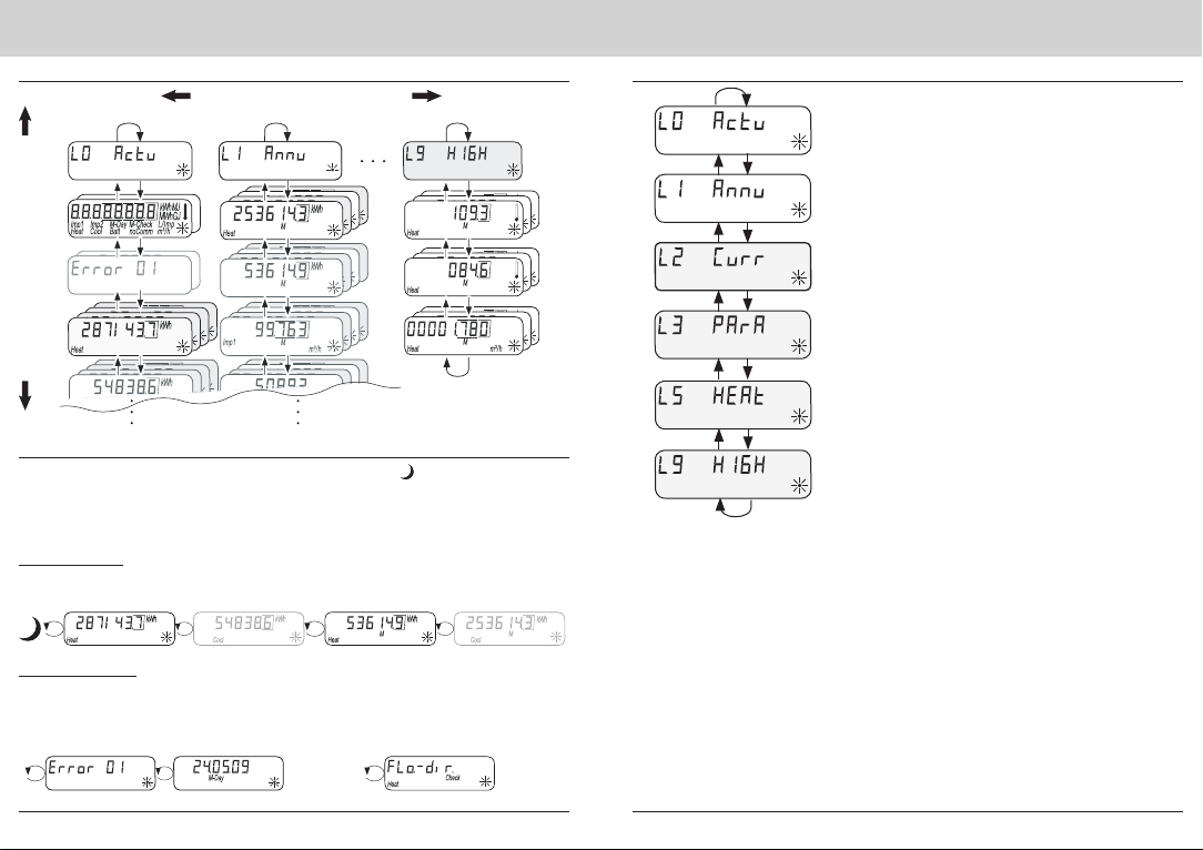
Operating scheme ........................................................................................ 8
Fast readout mode ....................................................................................... 8
Standard loop ............................................................................................ 8
Error messages ......................................................................................... 8
Display............................................................................................................ 9
Overview of levels ........................................................................................ 9
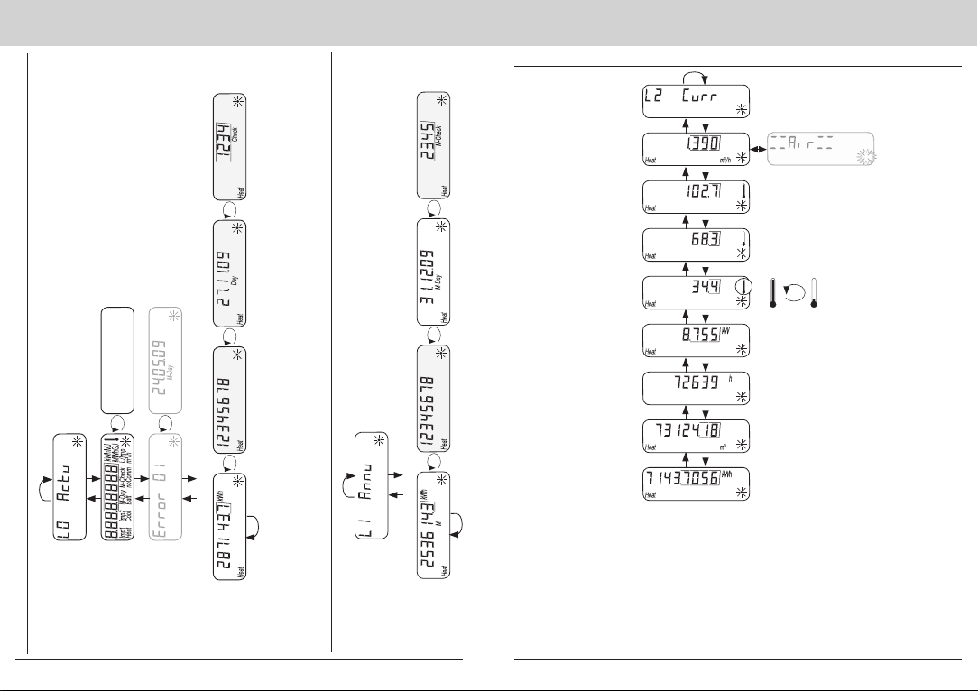
Display level L0 – Current consumption values.......................................... 10
Display level L1 – Annual consumption values........................................... 10
Display level L2 – Current values ................................................................11
Display level L3 – Parameters.................................................................... 12
Display level L5 – Monthly values heat ...................................................... 13
Display level L9 – Current values ............................................................... 14
Special operating states ............................................................................. 14
Error messages .......................................................................................... 15

4 5
Safety of lithium batteries
Certain heat meter components can be equipped with a lithium
battery. This type of battery is classied as hazardous.
VALID TRANSPORT REGULATIONS ARE TO BE ADHERED TO IN EACH
CASE! Inspection documents for the batteries used are available on request.
Handling lithium batteries
• store protected from dampness and moisture
• do not heat to above 100 °C or throw in re
• do not short-circuit
• do not open or damage
• do not charge
• do not store within reach of children
In the event of an accident, the following points must be heeded:
In the case of a leak:
- cover with sodium carbonate or an equivalent crystal soda
- make gases and vapours precipitate by spraying with water
- make sure of sufcient ventilation
- avoid any direct contact
In the event of injuries:
- If interior components of the dry element should come into contact with the
eyes, rinse thoroughly with water for 15 minutes.
- In the event of contact with the skin, wash with plenty of water and take off
soiled clothing.
- Move away from the accident spot following inhalation.
- Always consult a doctor.
In the event of a re:
- Use a Lith-X or Class-D re extinguisher.
- NEVER USE WATER FOR EXTINGUISHING PURPOSES
- Do not use CO2, halogen re extinguishers with dry substances or foam
extinguishers.
- Move away from the accident spot following inhalation and ventilate the area.
- Always consult a doctor.
Safety notes for lithium batteries
Technical data
CE conformity see Declaration of Conformity
Electromagnetic compatibility
Interference resistance EN 61000-6-2
Emitted interference EN 61000-6-3
Protection rating
IP protection ratingCalculator unit
Flow sensor
IP65 according to EN 60529
Heat meters
European Measuring Instruments Directive (MID)
EC type examination certicate
2004/22/EC
DE-14-MI004-PTB006
Heat meters
Model
EN1434
HMR5-xxAx-xxx0 xxxxx
Quality of heat medium in accordance with VDI guideline 2035
in accordance with AGFW-Norm 510
Inuencing quantities
Electromagnetic class E1
Mechanical class M2
Environment class A
Precision class 3
Norms and standards
Temperature range
as heat meter 20 °C ... 90 °C
permissible temperature difference
start of metering temperature differ-
ence
3 K - 160 K
1.0 K
Ambient temperature 5 °C ... 55 °C
Power supply
Lithium battery Nominal voltage 3.0 V
Service life > 6 (opt. 10) years + 6 months reserve
Display levels
Standard min. 2, up to 6
(depending on the version and options included)
Display 8-digit LCD + pictograms
Energy display kWh (opt. MWh, MJ, GJ)
Calculator unit

6 7
Technical data Device elements
(1) LC display - the display is off as standard (sleep mode). Every 36 seconds, the display
lights up brie y and indicates the current meter status, the
meter status on the due date and, if applicable, an er-
ror message (fast readout mode).
(2) Key <H> (horizontal)
(3) Key <V> (vertical)
(4) IrDA interface
(5) Interface cover
(6) Module interface
(7) Attachment holes for external optical modules
(8) User protection and slots for external
cable connections
meter status on the due date and, if applicable, an er-
Device elements
Status displays
Display Description
The data displayed apply for:
• Heat
• (empty) = Displayed value is the current value
• M (Memory) = Value on a monthly or due date
Displayed value is a date value:
• Day = Current date
• M-Day = Date applies for a saved annual
or monthly value
Displayed value is a checksum:
• Check =
Checksum refers to the current consumption value
• M-Check = Checksum is valid for a saved
annual or monthly value
Key assignment in standard mode
1. To activate LC display
Press the <H> key or
press the <V> key
2. To change from any position on one level to the next level
Press the <H> key
3. To change to the next display within one level
Press the <V> key
Flow sensor
Temperature sensor
Measuring element PT 1000 according to EN 60751
Version Type DS
Diameter 5.0 mm - 5.2 mm
Type of installation 5.0 mm - direct (ball valve) / indirect (immersion
sleeve)*
5.2 mm - direct (ball valve) / indirect (immersion
sleeve)*
Cable length Standard
Optional
1.5 m
3.0 m
* Note national and country-specific regulations concerning the use of immersion sleeves.
Connection sizes and weight 1.5 m³/h 2.5 m³/h
Length 110 mm 130 mm
Connection G ¾ B G 1 B
Weight 530 g 660 g
Installation position (calculator unit can be de-
tached)
any
Nominal ow qp 1.5 m³/h 2.5 m³/h
Minimum ow qi 15 l/h 25 l/h
Maximum ow qs 3000 l/h 5000 l/h
Start-up limit q01.5 l/h to 4.0 l/h 2.5 l/h to 6.5 l/h
Max. permissible operating pressure
Min. system pressure to avoid cavitation*
16 bar
1 bar
Temperature range 20 °C ... 90 °C
Dynamic range 1:100
* Cavity formation in fast- owing liquids
Water as medium
Only use water without chemical additives as the medium for this device.
Glycol additives or Natriumchlorid NaCI are expressly not permitted.

8 9
Display
Fast readout mode
The default setting is with the display off. (Sleep mode - ) Every 36 seconds
the display lights up brie y and indicates the current meter status, the meter
status on the due date and, if applicable, an error message.
Standard loop
(*) Meter status displays depend on the device con guration.
Error messages
Error code Error date
alt.
alt. alt.
Incorrect direction of ow
If a serious error occurs with the device, the
error code and error date are displayed be-
fore the meter status.
If the incorrect direction of ow is established,
an error message appears on the display as
shown.
Operating scheme
Display
L0
L1
L2
L3
L5
L9
Current consumption values
• Standard level
Annual consumption values
• Standard level
Current values
• Can be hidden individually
Parameter
• Can be hidden individually
Monthly values heat
• Can be switched off individually
Maximum values
• Can be switched off individually
Overview of levels
Changing the menu: Press key <V>
Changing the level: Press key <H>
Current meter status
heat
Meter status heat on
due date
(*) Current
meter status cool
(*) Meter status
cool on due date
alt.
alt.
alt.
alt.

10 11
Display level L0 – Current consumption values
Display
Displays the level
Display test – all on
Display test – all off alt.
Error number
Error date alt.
Current
consumption
values
Meter statuses Serial number Current date Checksum
alt. alt.alt. Heat
Display level L1 – Annual consumption values
Displays the level
Meter statuses Serial number Current due date Checksum
alt. alt.alt.
The displays coloured grey are optional or can be added and
switched off as required
Annual
consumption
values
Heat
Display
Display level L2 – Current values
alt.
Displays the level
Current
o w
Current supply ow
temperature
Current return ow
temperature
Current temperature
difference
Current
energy ow
Operating hours
Cumulated
volume
High-resolution
meter status heat
(*) Air in the
measuring
section
(*) The display "Air in the measuring sec-
tion" replaces the "Current ow" display if
air is detected in the measuring section.

12 13
Display
Display level L3 – Parameters
Displays the level
Date of next due date
Identication
Possible + activated
levels
This example:
Levels 2, 3 and 5 are shown,
4 x space = levels 4, 6, 7 and 8
not available,
= level 9 hidden
Calibrated checksum
rmware version
Serial number
Calibrated
rmware version
alt. alt.
Display
Display level L5 – Monthly values heat
Displays the level
Oldest monthly
value heat alt. alt.alt.
Latest monthly value
heat alt. alt.alt.
Date Serial numberChecksumMeter status
The displays coloured grey are optional or can be added and
switched off as required

14 15
Display
Display level L9 – Current values
alt.alt.
Max. temperature Date Period above limiting
value
Max. ow rate Period > qpDate
alt.alt.
alt.alt.
Displays
the level
Supply ow
Return ow
WMZ
Special operating states
Display Description Measures/Notes
• Communication credit of the
module interface or IrDA
exceeded
• Is eliminated after the credit pe-
riod (module = current day; IrDA
= current month) has been reset
automatically by the device
• The battery life has
expired.
• Device must be replaced
• Wrong direction of ow • Check installation (note arrow on
ow sensor)
• Check piping
• Check recirculating pumps and
thermostats for correct function
• Temperature sensors may
have been mixed up or tted
incorrectly
• Check whether ow sensor has
been tted in the right strand or
• check type of installation of
temperature sensor
• Air in the measuring section
• No correct ultrasonic meas-
uring signal
• Bleed the pipe system
Error messages
Display
Error display Error description Measures/Notes
• Hardware error or
damaged rmware
• Check ow sensor, connection
cable and calculator unit for external
damage
• Device must be replaced
• Add-on module was
paired with another
meter before
• The module has the measuring data
of another heat meter
• Save data, since these are overwrit-
ten after a short time
• Press any key to delete the display
• Supply ow
sensor broken
• Check temperature sensor and pipes
for mechanical damage
• Device must be replaced
• Short circuit
supply ow sensor
• Check temperature sensor and pipes
for mechanical damage
• Device must be replaced
• Return ow
sensor broken
• Check temperature sensor and pipes
for mechanical damage
• Device must be replaced
• Short circuit
return ow sensor
• Check temperature sensor and pipes
for mechanical damage
• Device must be replaced

QUNDIS GmbH
Sonnentor 2
D-99098 Erfurt
Tel. +49 (0)3 61 / 26 280-0
Fax +49 (0)3 61 / 26 280-175
www.qundis.com
Ultrasonic heat meter
Operating manual
Q heat 5 US
Type: Ultrasonic measuring technology
Document no.: FOM5ZZHEEN0 USDSP
Date published: 5.12.2014
Version: V3.00
Table of contents
Other QUNDIS Measuring Instrument manuals
Popular Measuring Instrument manuals by other brands

GHM
GHM Delta OHM LPPYRA13 operating manual

lanry
lanry DOF6000 Series manual

STUDER REVOX
STUDER REVOX C278 operating instructions

REV Ritter
REV Ritter EMT717ACTL operating instructions

3D Instruments
3D Instruments Accu-Cal Platinum Instruction booklet

Agilent Technologies
Agilent Technologies HP 8566B Operating and programming manual

Hanna Instruments
Hanna Instruments HI 9811-5 instruction manual

CLA-VAL
CLA-VAL XP2F Installation operation & maintenance

Dwyer Instruments
Dwyer Instruments DCG Series Installation and operating instructions

WIKA
WIKA 7000 Series operating instructions

Minolta
Minolta FLASHMETER VI - PART 2 manual

Pfeiffer Vacuum
Pfeiffer Vacuum GSD 350 OMNISTAR operating instructions