
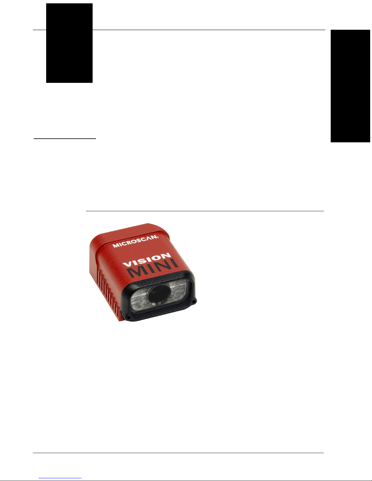
Chapter 1Introduction
1-4 Vision MINI Smart Camera Guide
Vision MINI Smart Camera Models
Table 1–1 lists and describes the Vision MINI Smart Camera models,
including acquisition modes and resolutions.
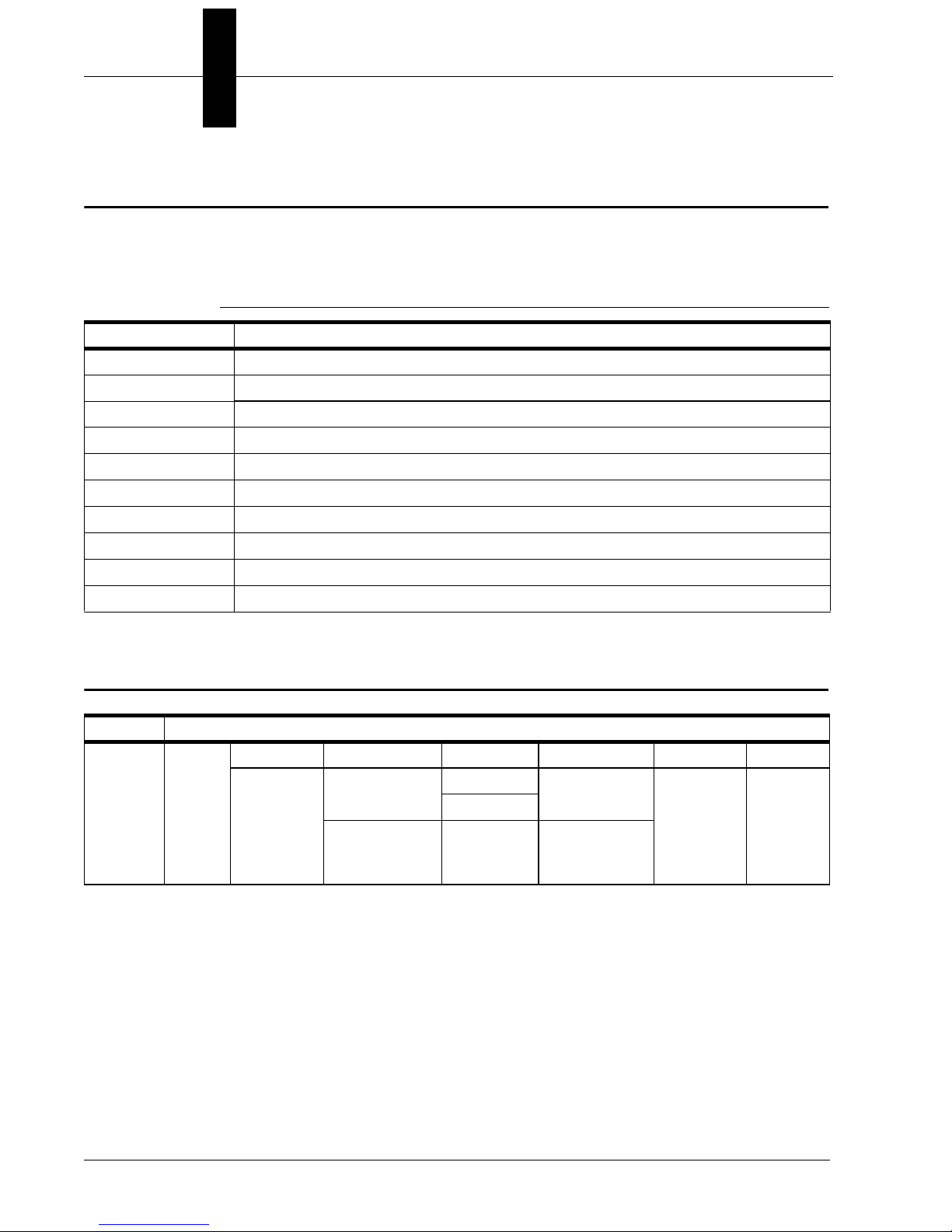
Part Number Structure
TABLE 1–1. Vision MINI Smart Camera Models
Part Number Vision MINI Smart Camera Model
GMV-6300-2100G Vision MINI Smart Camera, USB, SD, WVGA, Built-In Light, AutoVISION
GMV-6300-2102G Vision MINI Smart Camera, USB, SD, WVGA, Built-In Light, AutoVISION + Visionscape
GMV-6300-2110G Vision MINI Smart Camera, USB, SD, SXGA, Built-In Light, AutoVISION
GMV-6300-2112G Vision MINI Smart Camera, USB, SD, SXGA, Built-In Light, AutoVISION + Visionscape
GMV-6300-2172G Vision MINI Smart Camera, USB, SD, Color QXGA, Visionscape
GMV-6300-2200G Vision MINI Smart Camera, USB, HD, WVGA, Built-In Light, AutoVISION
GMV-6300-2202G Vision MINI Smart Camera, USB, HD, WVGA, Built-In Light, AutoVISION + Visionscape
GMV-6300-2210G Vision MINI Smart Camera, USB, HD, SXGA, Built-In Light, AutoVISION
GMV-6300-2212G Vision MINI Smart Camera, USB, HD, SXGA, Built-In Light, AutoVISION + Visionscape
GMV-6300-2272G Vision MINI Smart Camera, USB, HD, Color QXGA, Visionscape
GMV 6300
General
Machine
Vision
Vision
MINI
Comm Lens Sensor Options RoHS Custom
2 = USB 1 = Standard
Density
0 = WVGA 0 =
AutoVISION
G = RoHS
compliant
0 to 99
1 = SXGA
2 = High
Density
7 = Color
QXGA
2 =
AutoVISION +
Visionscape


 installation instructions")


