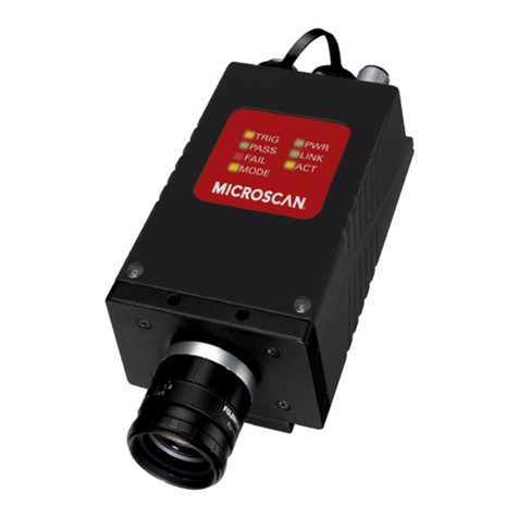
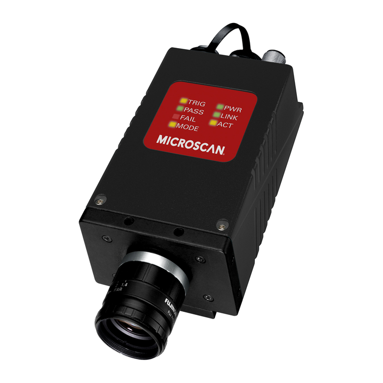
Microscan HawkEye 1500 Series Installation and operation manual

HawkEye™ 1500 Series
Verification Manual
EM-40393-1V241
v2.4.1, Nov 2008

Copyright and Disclaimer
Copyright ©2008 by Microscan Systems, Inc.
1201 S.W. 7th Street, Renton, WA, U.S.A. 98057
(425) 226-5700 FAX: (425) 226-8682
All rights reserved. The information contained herein is proprietary and is provided solely for the purpose of allowing
customers to operate and/or service Microscan manufactured equipment and is not to be released, reproduced, or used
for any other purpose without written permission of Microscan.
Throughout this manual, trademarked names might be used. Rather than place a trademark (™) symbol at every
occurrence of a trademarked name, we state herein that we are using the names only in an editorial fashion, and to the
benefit of the trademark owner, with no intention of infringement.
Disclaimer
The information and specifications described in this manual are subject to change without notice.
Latest Manual Version
For the latest version of this manual, see the Download Center on our web site at: www.microscan.com.
Technical Support
Microscan Systems, Inc.
1201 S.W. 7th Street
Renton, WA 98057
U.S.A.
Tel: 425 226 5700
Fax: 425 226 8250
Microscan Europe
Tel: 31 172 423360
Fax: 31 172 423366
Microscan Asia Pacific
R.O. Tel: 65 6846 1214
Fax: 65 6846 4641
Microscan Limited Warranty Statement and Exclusions
What Is Covered?
Microscan Systems Inc. warrants to the original purchaser that products manufactured by it will be free from defects in
material and workmanship under normal use and service for a period of one year from the date of shipment. This
warranty is specifically limited to, at Microscan’s sole option, repair or replacement with a functionally equivalent unit
and return without charge for service or return freight.
What Is Excluded?
This limited warranty specifically excludes the following: (1) Any products or parts that have been subject to misuse,
neglect, accident, unauthorized repair, improper installation, or abnormal conditions or operations; (2) Any products or
parts that have been transferred by the original purchaser; (3) Customer mis-adjustment of settings contrary to the
procedure described in the Microscan Systems Inc. owners manual; (4) Upgrading software versions at customer request
unless required to meet specifications in effect at the time of purchase; (5) Units returned and found to have no failure
will be excluded; (6) Claims for damage in transit are to be directed to the freight carrier upon receipt. Any use of the
product is at purchaser’s own risk. This limited warranty is the only warranty provided by Microscan Systems Inc.
regarding the product. Except for the limited warranty above, the product is provided “as is.” To the maximum extent
permitted by law, this express warranty excludes all other warranties, express or implied, including but not limited to,
implied warranties of merchantability and. Technical support questions may be directed to: [email protected]
Register your product with Microscan: www.microscan.com/register fitness for a particular purpose. Microscan Systems
Inc. does not warrant that the functions contained in the product will meet any requirements or needs purchaser may
have, or that the product will operate error free, or in an uninterrupted fashion, or that any defects or errors in the product
will be corrected, or that the product is compatible with any particular machinery.
Limitation of Liability
In no event shall Microscan Systems Inc. be liable to you or any third party for any special, incidental, or consequential
damages (including, without limitation, indirect, special, punitive, or exemplary damages for loss of business, loss of
profits, business interruption, or loss of business information), whether in contract, tort, or otherwise, even if Microscan
Systems Inc. has been advised of the possibility of such damages. Microscan Systems Inc.’s aggregate liability with
respect to its obligations under this warranty or otherwise with respect to the product and documentation or otherwise
shall not exceed the amount paid by you for the product and documentation. Some jurisdictions do not allow the
exclusion or limitation of incidental or consequential damages or limitations on an implied warranty, so the above
limitation or exclusion may not apply to you. This warranty gives you specific legal rights, and you may also have other
rights which may vary from state to state.
Tel: 425.226.5700 | Fax: 425.226.8250 | helpdesk@microscan.com


v2.4.1, Nov 2008 HawkEye™ 1500 Series Verification Manual v
Contents
PREFACE Welcome! ix
Purpose of This Manual ix
Manual Conventions ix
CHAPTER 1 Why Verification? 1-1
Introduction 1-1
Label Verification 1-3
Direct Part Mark (DPM) Verification 1-3
HawkEye™ 1500 Verification Options 1-4
Examples of Mark Quality Problems 1-5
CHAPTER 2 Calibration & Enabling Verification 2-1
HawkEye™ Normalization 2-2
Reflectance Calibration 2-6
Enabling Verification 2-11
CHAPTER 3 Data Matrix Verification 3-1
Verification Types 3-1
DPM 3-1
(VERI_FORMATTED) Output 3-2

Contents
vi HawkEye™ 1500 Series Verification Manual v2.4.1, Nov 2008
(VERI_DETAIL) Output 3-3
Delimited List of VERI_DETAIL Parameters 3-3
Parameters 3-4
ISO/IEC 16022:2000 3-5
(VERI_FORMATTED) Output 3-6
(VERI_DETAIL) Output 3-7
Delimited List of VERI_DETAIL Parameters 3-7
Parameters 3-8
ISO/IEC 15415:2004 3-8
(VERI_FORMATTED) Output 3-9
(VERI_DETAIL) Output 3-10
Delimited List of VERI_DETAIL Parameters 3-10
Parameters 3-11
AS9132 Rev. A, 2005 3-12
(VERI_FORMATTED) Output 3-13
(VERI_DETAIL) Output 3-14
Delimited List of VERI_DETAIL Parameters 3-14
Parameters 3-15
AIM DPM-1-2006 3-17
(VERI_FORMATTED) Output 3-18
(VERI_DETAIL) Output 3-19
Delimited List of VERI_DETAIL Parameters 3-20
Parameters 3-21
CHAPTER 4 Barcode Verification 4-1
ISO/IEC 15416:2000 4-1
(VERI_FORMATTED) Output 4-2
(VERI_DETAIL) Output 4-3
Delimited List of VERI_DETAIL Parameters 4-3
Parameters 4-4
APPENDIX A If You’re Writing Your Own VB Applications A-1
GetApertureString A-1
GetCalibratedString A-1
GetCellUnitReportString A-2
GetContrastReportString A-2
GetECCLevelString A-3

Contents
v2.4.1, Nov 2008 HawkEye™ 1500 Series Verification Manual vii
GetQuality20ZString A-3
APPENDIX B Verification Error Codes B-1
APPENDIX C AIM DPM-1-2006 Compliant Configuration C-1
Setting Up the UID-DPM Stand C-2
Attaching the Camera C-2
Assembling the Lights C-3
Preparing the Lenses C-3
Attaching the Lights to the Camera C-4
Recommended Verifier Setting with 25mm Lens C-5
Recommended Verifier Setting with 35mm Lens C-7
Index Index-1

Contents
viii HawkEye™ 1500 Series Verification Manual v2.4.1, Nov 2008

v2.4.1, Nov 2008 HawkEye™ 1500 Series Verification Manual ix
Preface
PREFACE Welcome!
Purpose of This Manual
This manual explains what verification is, how to use verification, and describes
verification parameters.
Manual Conventions
The following typographical conventions are used throughout this manual.
• Items emphasizing important information are bolded.
• Menu selections, menu items and entries in screen images are indicated as:
Run (triggered), Modify..., etc.

Preface
xHawkEye™ 1500 Series Verification Manual v2.4.1, Nov 2008

v2.4.1, Nov 2008 HawkEye™ 1500 Series Verification Manual 1-1
1
Why Verification?
1
CHAPTER 1 Why Verification?
This chapter introduces verification on the HawkEye™ 1500 Smart Camera.
Introduction
One axiom of implementing traceability is that the Data Matrix code will almost
never get better than it is at the instant it leaves the marker. Throughout the
marking process, verification ensures that the marks are being made correctly,
enabling corrections to be made to the marking method before it drifts out of
tolerance and produces unusable or incomplete marks.
To accomplish this, a verifier, as opposed to a reader, is needed to show that a
mark can be read, and to determine the quality of the mark. A reader only
provides a read pass/fail signal to the automated production line. This digital
signal does not provide any trending information to the marking equipment or
operators to alert them to a potential “line down” condition. Verifiers provide an
analog type sensor in the form of A through F letter grades. These grades provide
the marking equipment or the operators a warning that preventative maintenance
is needed. With that knowledge, the maintenance can be scheduled at a
convenient time versus whenever the machine breaks.

Chapter 1Why Verification?
1-2 HawkEye™ 1500 Series Verification Manual v2.4.1, Nov 2008
FIGURE 1–1. Verifying with a Reader
FIGURE 1–2. Verifying with a Verifier

Introduction
Why Verification?
1
v2.4.1, Nov 2008 HawkEye™ 1500 Series Verification Manual 1-3
Care should be taken, however, to use mark quality measurements appropriate
for direct part marking, because using legacy standards can lead to false alarms
or to missing serious marking problems. There are different verification
standards available to meet your needs. Data Matrix codes on labels can be
verified with AIM standard-compliant verifier systems. Directly marked parts,
however, require a type of verification specifically designed for that purpose.
Label Verification
In 1996, the Association for Automatic Identification and Mobility published a
set of criteria, known as the AIM Bar Code Print Quality Guideline, to allow
verification systems to grade a symbol by degree of acceptability (A through F).
Developed for high-contrast paper labels, this type of verification provides a
basic quantitative measure of print quality and allows printed 2-D codes to be
checked against a quality standard. The important note is that the process of
printing a Data Matrix on paper is an optimized process. The paper has been
bleached to be as white as possible and the ink has been dyed to be as black as
possible. Keeping this in mind, the grading thresholds of the AIM specification
are very restrictive because the mark quality is so high. Anything less would not
be appropriate or useful to the printing industry. Typical problems caught by
AIM include:
• Blocked holes
• Too much or too little ink
• Inconsistent inking
Direct Part Mark (DPM) Verification
Unlike the printing process, direct part marks are generally not optimized for
marking. It is more important for the parts to be optimized for their primary
purpose. It is more difficult to make a high contrast laser mark on bare aluminum
than on stainless steel; however, aluminum is specified more on aircraft parts due
to the lighter weight. The weight is more important than the markability. When
verifying the mark on aluminum, AIM generally fails the part due to low
contrast. This is where DPM verification is the appropriate verification method.
The DPM verifier is configurable to verify marks of different marking methods
and different materials. The threshold values for grading are fixed and cannot be
changed. You can configure pass/fail criteria. Then, each mark is measured
against the thresholds and is given a quality grade. Variation in the grade is
usually caused by one of the following:

Chapter 1Why Verification?
1-4 HawkEye™ 1500 Series Verification Manual v2.4.1, Nov 2008
• Marking parameters changing or marker failure
• Material formulation or surface texture changes
• Improperly fixtured or tracked parts
• Changes in environment like oil or ambient light on the part
• Improper fixturing or tracking of parts
Armed with the data from the verifier, the manufacturing line stays running
because the maintenance or changes necessary to improve the mark are
performed before the marks are unreadable.
The HawkEye™ 1500 is the only smart camera family with Microscan’ built-in
direct part mark verification capabilities.
HawkEye™ 1500 Verification Options
The HawkEye™ 1500 offers you the following verification options:
• ISO/IEC 16022:2000 verification, formerly AIM Specification
• ISO/IEC 15415:2004 Data Matrix verification (enabled by license key)
• AS9132 Rev A, 2005 Data Matrix Verification, formerly IAQG (enabled by
license key)
• DPM verification (enabled by license key)
• AIM DPM-1-2006 Data Matrix verification (enabled by license key)
• ISO/IEC 15416:2000 Barcode verification, formerly ANSI X3.182-1990
(enabled by license key)
You can select Good, Fair, and Poor options graphically, and ReadRunner
displays Good, Fair, and Poor feedback graphically. You can also assign Good,
Fair, and Poor states to opto-isolated outputs.

Examples of Mark Quality Problems
Why Verification?
1
v2.4.1, Nov 2008 HawkEye™ 1500 Series Verification Manual 1-5
Examples of Mark Quality Problems
• Improper or inconsistent mark dot/cell size
• Improper or inconsistent mark dot/cell location
• Improper overall mark geometry
• Mark or part surface damage
• Very low or inconsistent mark contrast
Offset
cell
Offset
cell

Chapter 1Why Verification?
1-6 HawkEye™ 1500 Series Verification Manual v2.4.1, Nov 2008

v2.4.1, Nov 2008 HawkEye™ 1500 Series Verification Manual 2-1
2
Calibration & Enabling
Verification
2
CHAPTER 2 Calibration & Enabling
Verification
HawkEye™ calibration consists of the following:
• HawkEye™ System Normalization
• Reflectance Calibration.
Calibration ensures that every verification system provides the repeatable result
per the relevant standard as compared to all other verification standards. Before
performing verification, the verifier must be calibrated. The calibration process
will set the contrast level and size measurement level of the verification system.
You MUST calibrate your HawkEye™ 1500 upon first time startup in your
production area and, again, if you move the smart camera or the ambient light
changes. The work environment where you will use your HawkEye™ 1500
should be a stable environment in terms of lighting. For example, if you work in
an office near windows, there might be read considerations when you perform a
read at noontime on a sunny day versus a read performed during 3rd shift at 2AM
on a moonless night. We suggest you position the HawkEye™ 1500 in a fairly
steady-state lighting environment where ambient light is consistent and at a low
level.
The HawkEye™ 1500 comes with a Calibration Target (Microscan part number
98-UA10-0CC0). Once you have positioned your smart camera into your work
space, you need to normalize and calibrate the system using this Calibration
Target.

Chapter 2Calibration & Enabling Verification
2-2 HawkEye™ 1500 Series Verification Manual v2.4.1, Nov 2008
For AIM DPM-1-2006 verification, please follow the recommendation in
Appendix C, “AIM DPM-1-2006 Compliant Configuration,” for setting up the
HawkEye™ 1510 and DOAL-50 light (AIM DPM compliant light for 90).
HawkEye™ Normalization
HawkEye™ Normalization sets the response of individual cameras to be linearly
proportional to contrast through different lighting environments and conditions.
The camera’s dark level offset, gain and exposure are controlled in order to
achieve this linear performance.
To perform HawkEye™ Normalization:
1. Start the HawkEye™ Normalization by selecting Start > Programs >
ReadRunner 2.4.1 > Utilities > HawkEye Normalization.
2. Using the “Select Camera to Normalize” drop down selection list, select the
camera that requires normalization, as shown in Figure 2–1.

Chapter 2Calibration & Enabling Verification
2-4 HawkEye™ 1500 Series Verification Manual v2.4.1, Nov 2008
FIGURE 2–2. Position the Calibration Standard
4. Click OK, and then click NORMALIZE.
The normalization will run for all of the lighting types supported by the
hardware.
At the completion of the normalization process, a report of the completed
results will be displayed and the program may then be closed, as shown in
Figure 2–3
Other manuals for HawkEye 1500 Series
2
Table of contents
Other Microscan Digital Camera manuals

Microscan
Microscan Vision MINI User manual

Microscan
Microscan Visionscape GigE User manual

Microscan
Microscan HAWK MV-4000 User manual

Microscan
Microscan Vision Hawk Smart Camera User manual

Microscan
Microscan VS-1 User manual

Microscan
Microscan HawkEye 1600T User manual

Microscan
Microscan Visionscape CMGC03 User manual

Microscan
Microscan Visionscape HE1600T User manual

Microscan
Microscan Vision HAWK GMV-6800-1000G User manual

Microscan
Microscan MicroHAWK MV-20 User manual