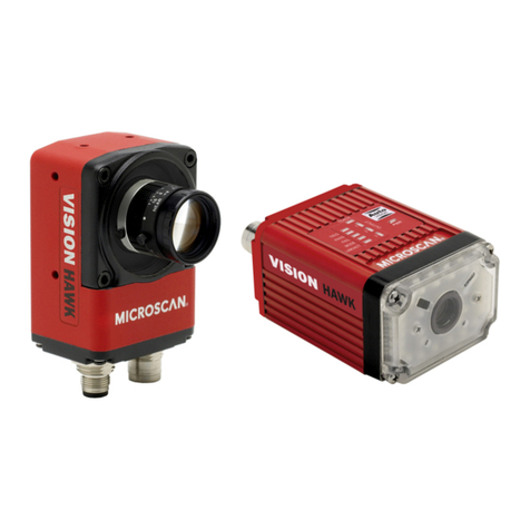
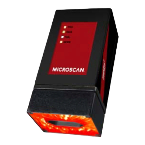
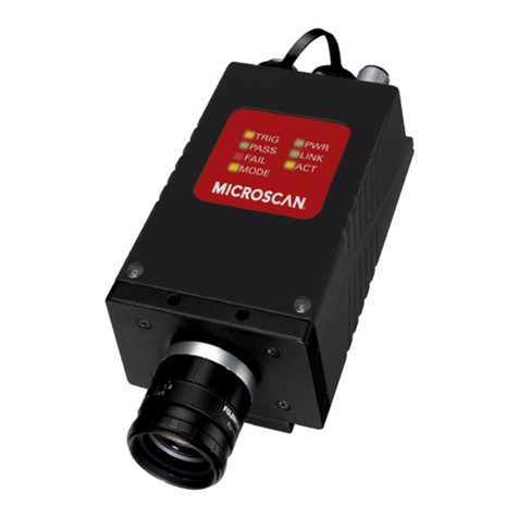
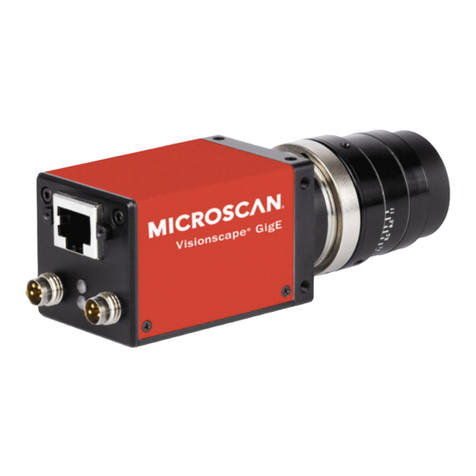
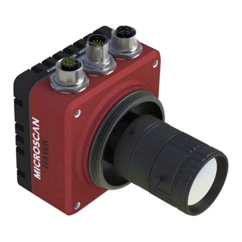
Microscan Visionscape HE1600T User manual

Getting Started With
Visionscape®
Smart Camera HE1600T
EM-40265-1V373
v3.7.3, Mar 2009

Copyright and Disclaimer
Copyright ©2009 by Microscan Systems, Inc.
1201 S.W. 7th Street, Renton, WA, U.S.A. 98057
(425) 226-5700 FAX: (425) 226-8682
All rights reserved. The information contained herein is proprietary and is provided solely for the purpose of allowing
customers to operate and/or service Microscan manufactured equipment and is not to be released, reproduced, or used
for any other purpose without written permission of Microscan.
Throughout this manual, trademarked names might be used. Rather than place a trademark (™) symbol at every
occurrence of a trademarked name, we state herein that we are using the names only in an editorial fashion, and to the
benefit of the trademark owner, with no intention of infringement.
Disclaimer
The information and specifications described in this manual are subject to change without notice.
Latest Manual Version
For the latest version of this manual, see the Download Center on our web site at: www.microscan.com.
Technical Support
Microscan Systems, Inc.
1201 S.W. 7th Street
Renton, WA 98057
U.S.A.
Tel: 425 226 5700
Fax: 425 226 8250
Microscan Europe
Tel: 31 172 423360
Fax: 31 172 423366
Microscan Asia Pacific
R.O. Tel: 65 6846 1214
Fax: 65 6846 4641
Microscan Limited Warranty Statement and Exclusions
What Is Covered?
Microscan Systems Inc. warrants to the original purchaser that products manufactured by it will be free from defects in
material and workmanship under normal use and service for a period of one year from the date of shipment. This
warranty is specifically limited to, at Microscan’s sole option, repair or replacement with a functionally equivalent unit
and return without charge for service or return freight.
What Is Excluded?
This limited warranty specifically excludes the following: (1) Any products or parts that have been subject to misuse,
neglect, accident, unauthorized repair, improper installation, or abnormal conditions or operations; (2) Any products or
parts that have been transferred by the original purchaser; (3) Customer mis-adjustment of settings contrary to the
procedure described in the Microscan Systems Inc. owners manual; (4) Upgrading software versions at customer request
unless required to meet specifications in effect at the time of purchase; (5) Units returned and found to have no failure
will be excluded; (6) Claims for damage in transit are to be directed to the freight carrier upon receipt. Any use of the
product is at purchaser’s own risk. This limited warranty is the only warranty provided by Microscan Systems Inc.
regarding the product. Except for the limited warranty above, the product is provided “as is.” To the maximum extent
permitted by law, this express warranty excludes all other warranties, express or implied, including but not limited to,
implied warranties of merchantability and. Technical support questions may be directed to: [email protected]
Register your product with Microscan: www.microscan.com/register fitness for a particular purpose. Microscan Systems
Inc. does not warrant that the functions contained in the product will meet any requirements or needs purchaser may
have, or that the product will operate error free, or in an uninterrupted fashion, or that any defects or errors in the product
will be corrected, or that the product is compatible with any particular machinery.
Limitation of Liability
In no event shall Microscan Systems Inc. be liable to you or any third party for any special, incidental, or consequential
damages (including, without limitation, indirect, special, punitive, or exemplary damages for loss of business, loss of
profits, business interruption, or loss of business information), whether in contract, tort, or otherwise, even if Microscan
Systems Inc. has been advised of the possibility of such damages. Microscan Systems Inc.’s aggregate liability with
respect to its obligations under this warranty or otherwise with respect to the product and documentation or otherwise
shall not exceed the amount paid by you for the product and documentation. Some jurisdictions do not allow the
exclusion or limitation of incidental or consequential damages or limitations on an implied warranty, so the above
limitation or exclusion may not apply to you. This warranty gives you specific legal rights, and you may also have other
rights which may vary from state to state.
Tel: 425.226.5700 | Fax: 425.226.8250 | helpdesk@microscan.com


v3.7.3, Mar 2009 Getting Started With Visionscape® Smart Camera v
Contents
PREFACE Welcome! vii
Purpose of This Manual vii
Manual Conventions vii
CHAPTER 1 Using a Visionscape® Smart Camera for the First
Time 1-1
Establishing a Network Connection & Making a FrontRunner™
Device Button for Your Camera 1-1
Creating a New Job to Acquire Images 1-5
CHAPTER 2 The 1600T in Action - Simple Examples 2-1
Icons 2-2
Simple Blob Tool 2-3
Simple Flaw Tool 2-12
Simple Fast Edge Tool 2-18
Simple Data Matrix Tool 2-34
Training Tools 2-39
Where To Now? 2-40

Contents
vi Getting Started With Visionscape® Smart Camera v3.7.3, Mar 2009
CHAPTER 3 The 1600T in Action - Advanced Example 3-1
Advanced Example Using Multiple Tools 3-2
Input Datums 3-2
Procedure 3-2
Where To Now? 3-20
Index Index-1

v3.7.3, Mar 2009 Getting Started With Visionscape® Smart Camera vii
Preface
PREFACE Welcome!
Purpose of This Manual
This manual is designed to get you up and running with your Visionscape®Smart
Camera HE1600T quickly and confidently.
Please don’t be intimidated by the size of this Getting Started manual. It contains
a large number of images that will help you as you create new Jobs using the
tutorials.
Manual Conventions
The following typographical conventions are used throughout this manual.
• Items emphasizing important information are bolded.
• Menu selections, menu items and entries in screen images are indicated as:
Run (triggered), Modify..., etc.

Preface
viii Getting Started With Visionscape® Smart Camera v3.7.3, Mar 2009

v3.7.3, Mar 2009 Getting Started With Visionscape® Smart Camera 1-1
1
Using a Visionscape®
Smart Camera for the
1
CHAPTER 1 Using a Visionscape®Smart
Camera for the First Time
Before proceeding with this chapter, you should have:
• Completed installation of the Visionscape®software (see Chapter 3 of
Getting Started With Visionscape®Framegrabber Boards)
• Suitably mounted and wired the Visionscape® Smart Camera HE1600T (see
Chapter 2 of Visionscape® Smart Camera HE1600T Guide)
Establishing a Network Connection & Making a
FrontRunner™ Device Button for Your Camera
This section assumes familiarity with basic wired networking concepts such as IP
addresses and DHCP servers. If these terms are not familiar, please talk to your
IT department and see “Setting Up Network Communications” in the
Visionscape® Smart Camera HE1600T Guide.
A network connection is required to communicate with the Visionscape®Smart
Camera HE1600T. In order that the Visionscape®Smart Camera HE1600T be
recognized, it must have a valid IP address. As shipped, the Visionscape®Smart
Camera HE1600T will try to obtain an IP address from a DHCP server so, if your
network is configured for DHCP, you will be able to connect to your camera
without changing any settings. However, if your network requires a static IP
address to be assigned, or if you would like to use a cross-link cable, please see

Chapter 1Using a Visionscape® Smart Camera for the First Time
1-2 Getting Started With Visionscape® Smart Camera v3.7.3, Mar 2009
“Setting Up Network Communications” in the Visionscape® Smart Camera
HE1600T Guide.
Note: When using a Visionscape®Smart Camera HE1600T in a production
environment, it MUST be programmed to use a static IP address instead of
DHCP. This is to prevent loss of communications due to IP lease renewal by the
DHCP server.
Follow these steps when connecting the Visionscape®Smart Camera HE1600T
for the first time:
1. Connect the Visionscape®Smart Camera HE1600T to the same network as
the PC that will be running the FrontRunner™ software.
2. Apply power to the Visionscape®Smart Camera HE1600T; be sure to do
this AFTER making the physical connection to the network.
3. Start the FrontRunner™ application by selecting Start > Visionscape >
Visionscape FrontRunner. The main FrontRunner™ screen is displayed,
as shown in Figure 1–1.
FIGURE 1–1. FrontRunner™ Main Screen
4. Select View > Network Overview to display the Network Overview
window, as shown in Figure 1–2.
Device Buttons
Device Bar
Toolbar

Establishing a Network Connection & Making a FrontRunner™
Using a Visionscape®
Smart Camera for the
1
v3.7.3, Mar 2009 Getting Started With Visionscape® Smart Camera 1-3
FIGURE 1–2. Network Overview Screen — No Camera Selected
Your camera should appear in the network overview list. The camera name
will be of the form HawkeyeXXXXXX, where the X’s represent the last part
of the camera’s MAC address.
5. Click on the row that lists your camera. The network information area should
update and display the Change Network Settings … button, as shown in
Figure 1–3.
FIGURE 1–3. Network Overview Screen — Camera Selected
6. If the info area displays a red background identifying a camera
communication problem, it means that the camera and the PC, even though
connected to the same network, are not using the same logical IP addressing.
See “Setting Up Network Communications” in the Visionscape® Smart
Camera HE1600T Guide to correct the communication problem.
7. Click the Change Network Settings button, which displays the login screen.
Enter the default user name (hawkeye) and password (“vision”) and click
OK. You will see the Change HawkEye Network Settings dialog box
(Figure 1–4), which allows you to change the name of your camera.

Chapter 1Using a Visionscape® Smart Camera for the First Time
1-4 Getting Started With Visionscape® Smart Camera v3.7.3, Mar 2009
FIGURE 1–4. Change Network Settings Dialog Box
8. Highlight the existing camera name, type in a new name (no spaces are
allowed), and click OK. You will see the name of your camera change in the
network overview. You can close the Network Overview Window.
9. From FrontRunner™, click to display the Select Device dialog box.
10. Click on the camera name you just assigned and click OK. You will see a
new device button appear for your camera, as shown in Figure 1–5.
FIGURE 1–5. HawkEyeE1000E Device Button Added
Note: The green triangle symbol indicates that the camera is currently
running a job.

Creating a New Job to Acquire Images
Using a Visionscape®
Smart Camera for the
1
v3.7.3, Mar 2009 Getting Started With Visionscape® Smart Camera 1-5
11. From this point on, you can simply click on the device button for your
camera to establish a connection.
Creating a New Job to Acquire Images
The instructions that the Visionscape®Smart Camera HE1600T camera performs
in a particular application are called “Steps”, and the complete collection of steps
is called a “Job”. To do anything, even to take a picture, the Visionscape®Smart
Camera HE1600T requires a Job. Use the following procedure to create a new
Job:
1. Click the device button for your camera.
2. Take control of the camera by clicking .
This will display the Login to Device dialog box, where you should enter the
username (hawkeye) and password (“vision”) and then click OK.
3. To begin creating a new Job, select File > New Job (or click ).
FrontRunner™ displays the screen shown in Figure 1–6.
FIGURE 1–6. FrontRunner Main Screen After Clicking New Job
Acquire New Image
Live Video

Chapter 1Using a Visionscape® Smart Camera for the First Time
1-6 Getting Started With Visionscape® Smart Camera v3.7.3, Mar 2009
4. To acquire a new image, click You should see an image appear in the
display area.
5. To display a “live” image, click (Click it again to exit live video.)
6. To bring up the step editing environment, click
You will see a hierarchy of steps on the left hand side of the editor, as shown
in Figure 1–7.
FIGURE 1–7. Hierarchy of Steps

Creating a New Job to Acquire Images
Using a Visionscape®
Smart Camera for the
1
v3.7.3, Mar 2009 Getting Started With Visionscape® Smart Camera 1-7
7. Select the step named “Acquire”. After you select the Acquire step, the right
hand side of the editor will display the various parameters and settings that
can be modified. Of immediate interest is Exposure Time. You can click on
the spreadsheet cell with the current Exposure Time value to change it.
Reducing the exposure time will darken the image, while increasing it will
make the image brighter.
So far, the Job you are manipulating exists only on the PC. You are using the
Job in “Setup Mode”, which allows you to create, edit, and debug Jobs on
the PC.
8. To transfer the Job to the camera, click
If you want the Job to be non-volatile (still be loaded on the camera when it
is rebooted), then click
9. Now that there is a Job loaded onto the camera, start it by clicking
This will switch FrontRunner™ to a runtime display which, in the case of
this example, will simply display the image, as shown in Figure 1–8.

Chapter 1Using a Visionscape® Smart Camera for the First Time
1-8 Getting Started With Visionscape® Smart Camera v3.7.3, Mar 2009
FIGURE 1–8. Image Displayed by Your New Job
Note: Notice the statistics at the bottom of the display.

v3.7.3, Mar 2009 Getting Started With Visionscape® Smart Camera 2-1
2
The 1600T in Action -
Simple Examples
2
CHAPTER 2 The 1600T in Action - Simple
Examples
This chapter contains simple tutorial examples to help you become familiar with
various FrontRunner™ tools:
• “Simple Blob Tool” on page 2-3
• “Simple Flaw Tool” on page 2-12
• “Simple Fast Edge Tool” on page 2-18
• “Simple Data Matrix Tool” on page 2-34
Notice that each sections lists the complete Job (xxxxx.AVP) that corresponds to
the Job you will create.

Chapter 2The 1600T in Action - Simple Examples
2-2 Getting Started With Visionscape® Smart Camera v3.7.3, Mar 2009
Icons
Table 2–1 describes the icon used in this chapter:
TABLE 2–1. Icons and What They Mean
Icon What It Means
This is step #1 of a procedure.
Click the left mouse button.
This is step #2 of a procedure.
Click the left mouse button.
1
2

Simple Blob Tool
The 1600T in Action -
Simple Examples
2
v3.7.3, Mar 2009 Getting Started With Visionscape® Smart Camera 2-3
Simple Blob Tool
FrontRunner™ Job:
Start > Visionscape > Visionscape Tutorials & Samples > Tutorials > HawkEye
1600T > Simple Blob Tool > tutorial_blob.avp
The Blob Tool performs connectivity analysis on an image, finding groups of
connected pixels with gray levels above or below a threshold. Each group is
called a blob. The Blob Tool records all the detected blobs into a blob tree. For
each blob, the tool calculates many geometric features including the length,
width, area, etc. In addition, the number of blobs and number of parts in the
region of interest (ROI) are calculated. A part is a blob that has the opposite color
of the background. A hole is a blob with the same color as the background.
This example counts the number of pips on a die.
1. Start FrontRunner™ by selecting Start > Visionscape > Visionscape
FrontRunner. FrontRunner™ displays its main window.
2. Do either of the following:
a. For a camera already added to FrontRunner™, simply click the camera
button.
b. For a camera that has not been added to FrontRunner™, click
FrontRunner™ displays the Select Device dialog box. Select a camera
and click OK.
3. Take control of the camera by clicking . FrontRunner™ displays the
Login to Device dialog box.
Note: You will not see this screen if no login parameters are set.
4. Enter your username (defaults is “hawkeye”) and password (default is
“vision”), and click OK.
5. Stop the camera by clicking . FrontRunner™ displays the Device State
Changed dialog box. Because we’re creating a new Job, click No.
6. Start creating a new Job by clicking Create New Program, and then
Editor, as shown in Figure 2–1.

Chapter 2The 1600T in Action - Simple Examples
2-4 Getting Started With Visionscape® Smart Camera v3.7.3, Mar 2009
FIGURE 2–1. Start Creating New Job
The camera will change to Edit Mode (indicated by the pencil next to the
camera icon).
Note: Maximize or minimize the Editor as needed.
7. In the left pane, highlight Acquire in the Step Tree.
Note: You may have to click the Acquire tab in the properties window.
FrontRunner™ displays the Acquire properties page.
8. Adjust the following Acquire properties:
–Picture Mode — Set to Load Images from File.
–File List — Click <empty>, and then Add... to display the Open dialog
box. Browse for the file Die 1 Pip.tif from Windows. It’s located at:
C:\Vscape\Tutorials & Samples\Tutorials\HawkEye 1600T\Simple
Blob Tool
Select Die 1 Pip.tif and click Open.
Note: These files were installed from the installation CD onto your hard
drive when you installed Visionscape®. If you installed Visionscape®
to a location other than C:\vscape, replace it with the appropriate
drive and directory designation.
9. Highlight Snapshot in the Step Tree. Right click Snapshot and click Insert
Into. FrontRunner™ displays the Insert Step window. Double click on Blob
Tool to insert it into the Snapshot.
1
2
Other manuals for Visionscape HE1600T
1
Table of contents
Other Microscan Digital Camera manuals

Microscan
Microscan MicroHAWK MV-20 User manual

Microscan
Microscan HawkEye 1500 Series Installation and operation manual

Microscan
Microscan Vision MINI User manual

Microscan
Microscan Visionscape HE1600T User manual

Microscan
Microscan Vision Hawk Smart Camera User manual

Microscan
Microscan HAWK MV-4000 User manual

Microscan
Microscan VS-1 User manual

Microscan
Microscan Vision MINI Xi Smart Camera User manual

Microscan
Microscan HawkEye 1600T User manual

Microscan
Microscan MicroHAWK MV-20 User manual