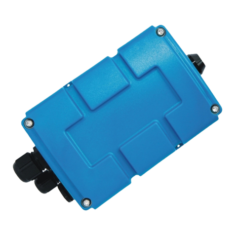
Microtronics myDatalogEASY IoTmini User manual

301115 | Rev.01
Cover
Valid from:
lFirmware version: 01v015
lServer version: 47.10
lHardware version: 1.0
User manual
myDatalogEASY IoTmini


Chapter 1 Table of contents
Cover 1
Chapter 1 Table of contents 3
Chapter 2 Declaration of conformity 11
Chapter 3 Specifications 13
Chapter 4 General specifications 17
4.1 Translation 17
4.2 Copyright 17
4.3 General descriptive names 17
4.4 Safety instructions 17
4.4.1 Use of the hazard warnings 18
4.4.2 General safety instructions 18
4.4.3 Safety and preventative measures for handling wireless modules 19
4.4.3.1 Safety and precautionary measures for the wireless module installation 19
4.4.3.2 Safety measures for installing the antenna 19
4.5 Overview 20
4.5.1 Block diagram 21
4.6 Intended use 22
4.7 General product information 22
4.8 Device labelling 23
4.9 Installation of spare and wear parts 24
4.10 Storage of the product 24
4.11 Warranty 24
4.12 Disclaimer 25
4.13 Obligation of the operator 25
4.14 Personnel requirements 26
Chapter 5 Functional principle 27
5.1 Recommended procedure 29
5.1.1 Development of M2M/IoT application 29
5.2 Functionality of the internal data memory 29
5.3 Memory organisation 31
5.4 Error handling 32
Rev. 01 3

5.5 Registration memory blocks 32
5.5.1 REG_SYS_FLASH 33
5.5.2 REG_APP_OTP 33
Chapter 6 Storage, delivery and transport 35
6.1 Inspection of incoming deliveries 35
6.2 Scope of supply 35
6.3 Storage 36
6.4 Transport 36
6.4.1 Transporting power supply units 36
6.5 Return 38
Chapter 7 Installation 39
7.1 Dimensions 39
7.2 Assembling the myDatalogEASYIoTmini 39
7.3 Installing the myDatalogEASYIoTmini 45
7.3.1 Wall mounting 46
7.3.2 Top-hat rail assembly 47
7.3.3 Pipe assembly 48
7.4 Safety instructions for the cabling 49
7.4.1 Information on preventing electrostatic discharges (ESD) 50
7.5 Electrical installation 50
7.5.1 Connecting the sensors, actuators and power supply 50
7.5.1.1 Connection examples 54
7.5.2 Connecting the LoRa antenna 54
7.5.3 Technical details about the universal inputs 55
7.5.3.1 0/4 to 20mA mode 55
7.5.3.2 0 to 2V mode 55
7.5.3.3 0 to 10V mode 55
7.5.3.4 Standard digital modes (PWM, frequency, digital, counter) 56
7.5.4 Technical details about the PT100/1000 interface 56
7.5.5 Technical details about the RS485 interface 56
7.5.6 Technical details about the RS232 interface 57
7.5.7 Technical details about the USB interface 58
7.5.8 Technical details about the outputs 59
4Rev. 01

Chapter 1 Table of contents
7.5.8.1 Switchable sensor supply VOUT 59
7.5.8.2 Switchable sensor supply VEXT 60
7.5.8.3 Switchable sensor supply VEXTRS232 61
7.5.8.4 Isolated switch contact (NO, CC) 61
7.5.9 Technical details about energy management 61
7.5.10 Technical details about the energy supply 62
7.5.10.1 PSU413D+ AP (300524) 63
7.5.10.2 PSU413D AP (300525) 63
7.5.10.3 PSU713 BP (300526) 64
7.5.10.4 PSU DC (300529) 64
7.5.10.5 PSU AC (300558) 64
7.5.10.6 PSU DC+ (300798) 65
7.5.11 Technical details about the system time 65
Chapter 8 Initial Start-Up 67
8.1 User information 67
8.2 Applicable documents 67
8.3 General principles 67
8.4 Commissioning the system 67
8.5 Testing communication with the device 69
Chapter 9 User interfaces 71
9.1 User interface on the myDatalogEASYIoTmini 71
9.1.1 Operating elements 71
9.1.1.1 Solenoid switch 71
9.1.1.2 Two-colour LED 71
9.2 User interface on the myDatanet server 72
9.2.1 Site configuration 72
9.2.1.1 Site 72
9.2.1.2 Comments 72
9.2.1.3 Control 73
9.2.1.4 Configuration 0 - Configuration 9 73
9.2.1.5 Alarm settings 74
9.2.1.6 Basic settings 75
9.2.1.7 FTP export settings 75
Rev. 01 5

9.2.2 Device configuration 76
9.2.2.1 Comments 76
9.2.2.2 Measurement instrument 76
Chapter 10 rapidM2M Studio 79
10.1 General 79
10.2 Prerequisites 80
Chapter 11 myDatanet server 81
11.1 Recommended procedure 81
11.1.1 Creating the site 81
Chapter 12 Device Logic (Pawn) 83
12.1 General 83
12.1.1 Direct entry of a device logic 83
12.1.2 Uploading a binary file 83
12.1.3 Using the CODEbed of the web-based development environment rapidM2M Studio 83
12.2 Compiler options 84
12.3 rapidM2M Device API 84
12.3.1 Constants 84
12.3.2 Timer, date & time 85
12.3.2.1 Arrays with symbolic indices 85
12.3.2.2 Constants 85
12.3.2.3 Functions 85
12.3.3 Uplink 90
12.3.3.1 Constants 90
12.3.3.2 Callback functions 90
12.3.3.3 Functions 91
12.3.4 System 95
12.3.4.1 Arrays with symbolic indices 95
12.3.4.2 Constants 95
12.3.4.3 Functions 97
12.3.5 Encoding 99
12.3.5.1 Constants 99
12.3.5.2 Functions 100
12.3.6 RS232, RS485 105
6Rev. 01

Chapter 1 Table of contents
12.3.6.1 Constants 105
12.3.6.2 Callback functions 105
12.3.6.3 Functions 107
12.3.7 LoRa 113
12.3.7.1 Constants 113
12.3.7.2 Callback functions 113
12.3.7.3 Functions 114
12.3.8 Registry 117
12.3.8.1 Constants 117
12.3.8.2 Callback functions 118
12.3.8.3 Functions 118
12.3.9 Position 122
12.3.9.1 Arrays with symbolic indices 122
12.3.9.2 Constants 122
12.3.9.3 Functions 124
12.3.10 Math 128
12.3.11 Char & String 131
12.3.12 CRC & hash 136
12.3.12.1 Arrays with symbolic indices 136
12.3.12.2 Functions 136
12.3.13 Various 137
12.3.13.1 Arrays with symbolic indices 137
12.3.13.2 Constants 138
12.3.13.3 Functions 138
12.3.14 Console 144
12.3.15 Universal inputs 145
12.3.15.1 Constants 145
12.3.15.2 Functions 146
12.3.16 Outputs 149
12.3.16.1 Constants 149
12.3.16.2 Functions 149
12.3.17 LED 154
12.3.17.1 Constants 154
Rev. 01 7

12.3.17.2 Functions 155
12.3.18 Solenoid switch 157
12.3.18.1 Constants 157
12.3.18.2 Callback Funktionen 157
12.3.18.3 Functions 158
12.3.19 Power management 159
12.3.19.1 Arrays with symbolic indices 159
12.3.19.2 Constants 159
12.3.19.3 Callback functions 160
12.3.19.4 Functions 160
12.4 Device Logic error codes 161
12.5 Syntax 164
12.5.1 General syntax 164
12.5.1.1 Format 164
12.5.1.2 Optional semicolons 164
12.5.1.3 Comments 164
12.5.1.4 Identifier 164
12.5.1.5 Reserved keywords 164
12.5.1.6 Numerical constants 165
12.5.1.6.1 Numerical integer constants 165
12.5.1.6.2 Numerical floating-point constants 165
12.5.2 Variables 165
12.5.2.1 Declaration 165
12.5.2.2 Local declaration 165
12.5.2.3 Global declaration 165
12.5.2.4 Static local declaration 166
12.5.2.5 Static global declaration 166
12.5.2.6 Floating point values 166
12.5.3 Constant variables 166
12.5.4 Array variables 166
12.5.4.1 One-dimensional arrays 166
12.5.4.2 Initialisation 167
12.5.4.3 Progressive initialisation for arrays 167
8Rev. 01

Chapter 1 Table of contents
12.5.4.4 Multi-dimensional arrays 167
12.5.4.5 Arrays and the "sizeof" operator 168
12.5.5 Operators and expressions 169
12.5.5.1 Notational conventions 169
12.5.5.2 Expressions 169
12.5.5.3 Arithmetic 169
12.5.5.4 Bit manipulation 170
12.5.5.5 Assignment 170
12.5.5.6 Comparative operators 171
12.5.5.7 Boolean 171
12.5.5.8 Other 172
12.5.5.9 Priority of the operators 172
12.5.6 Statements 173
12.5.6.1 Statement label 173
12.5.6.2 Composite statements 174
12.5.6.3 Expression statement 174
12.5.6.4 Empty statement 174
12.5.6.5 Assert expression 174
12.5.6.6 Break 175
12.5.6.7 Continue 175
12.5.6.8 Do statement while (expression) 176
12.5.6.9 Exit expression 176
12.5.6.10 For (expression1; expression2; expression3) statement 176
12.5.6.11 Goto label 177
12.5.6.12 If (expression) statement1 else statement2 177
12.5.6.13 Return expression 177
12.5.6.14 switch (expression) {case list} 177
12.5.6.15 While (expression) statement 178
12.5.7 Functions 179
12.5.7.1 Function arguments ("call-by-value" versus "call-by-reference") 179
12.5.7.2 Named parameters versus fixed parameters 181
12.5.7.3 Standard values of function arguments 181
12.6 Differences to C 182
Rev. 01 9

Chapter 13 Data Descriptor 185
Chapter 14 API 187
14.1 Frontend API 187
14.2 rapidM2M Playground 187
14.2.1 Overview 188
Chapter 15 Maintenance 189
15.1 General maintenance 189
15.2 Replacing the power supply unit 189
15.2.1 Charging the power supply unit 191
15.3 Power supply units with integrated energy store 193
Chapter 16 Removal/disposal 195
Chapter 17 Troubleshooting and repair 197
17.1 General problems 197
17.2 Log entries and error codes 199
17.3 Evaluating the device log 201
17.3.1 Evaluating the device log on the myDatanet server 201
17.3.2 Evaluating the device log using DeviceConfig 201
Chapter 18 Spare parts and accessories 203
18.1 Chargeable features 203
18.2 Assembly sets 203
18.3 Antennas 203
18.4 Power supply units 204
18.5 Charging devices and power supply units 204
18.6 Other accessories 204
Chapter 19 Document history 205
Chapter 20 Glossary 207
Chapter 21 Contact information 209
10 Rev. 01

Chapter 2 Declaration of conformity
Rev. 01 11


Chapter 3 Specifications
Voltage
supply
Rechargeable battery:
lPSU413D+ AP : 13,6Ah, Li-Ion , integrated overvoltage protection
lPSU413D AP : 13,2Ah, Li-Ion , integrated overvoltage protection
Battery:
lPSU713 BP : 13Ah
Direct power supply:
lPSU DC : DC protective circuit
lPSU DC+ : 900mAh, Li-Po , DC protective circuit
lPSU AC : 900mAh, Li-Po , 230VAC power supply unit
Additional information is provided in "Technical details about the energy supply" on page 62.
Supply or
charging
voltage
12...32VDC (max. 12W )
Housing Material:
Weight:
Degree of protection:
Dimensions (WHD):
ABS / PC (housing/cover)
330g (without power supply unit)
IP66
86 x 175 x 64mm (without antenna)
Operating
temperature
-20...+60°C
Air humidity 15...90%rH non-condensing
Storage
temperature
-30...+85°C
Display Two-colour LED with selectable function:
lSignalling the operating state (controlled by the FW)
lFunction freely useable (controlled by the device logic)
Operation Solenoid switch with selectable function:
lInitiation of the transmission (evaluated by the FW)
lFunction freely useable (evaluated by the device logic)
Antenna
connector
FME-M
Rev. 01 13

Universal
inputs 1) 4 x analogue or digital
Modes:
l0/4...20mA: Resolution 6,3µA, max. 23,96mA, load 96Ω
l0...2V: Resolution 610µV, max. 2,5V, load 10k086
l0...10V: Resolution 7,97mV, max. 32V, load 4k7
lPWM: 1...99%, max. 100Hz, min. pulse length 1ms, load 10k086
lFrequency: 1...1000Hz, 10k086
lDigital: max. 32V, low <0,99V, high >2,31V, load 10k086
lCounter: min. pulse length 1ms, load 10k086
Additional information is provided in "Technical details about the universal inputs" on page
55.
System time Hardware real-time clock with its own buffer battery (service life >10 years) and automatic
time synchronisation with the server
Additional information is provided in "Technical details about the system time" on page 65.
Internal
sensors
Internal housing temperature
lMeasurement range: -20...+60°C
lResolution: 0,1°C
Humidity in the housing
lMeasurement range: 0...100% rH
lResolution: 0,1% rH
External
temperature
sensor 2)
1 x PT100/1000 (including auto detection)
Additional information is provided in "Technical details about the PT100/1000 interface" on
page 56.
Serial
interface
1 x RS232 (4-wire) 3)
lBaud rate: 600-115200
lStop bits: 1, 2
lParity: N, E, O
lData bits: 7, 8
lFlow control: Off, RTS/CTS
1 x RS485 (2-wire) 4) 5)
lBaud rate: 600-115200
lStop bits: 1, 2
lParity: N, E, O
lData bits: 7, 8
lLoad resistance: Off, 120Ω
Additional information is provided in "Technical details about the RS485 interface" on page
56 and "Technical details about the RS232 interface" on page 57.
14 Rev. 01

Chapter 3 Specifications
Outputs 2 x switchable 3,3V supply (max. 180mA )
1 x switchable and adjustable sensor supply
The device logic can be used to vary the output voltages in the range of 5...24V .
l5Vnominal: 4,75V at Iout = 50mA
l12Vnominal: 11,7V at Iout = 50mA
l15Vnominal: 14,7V at Iout = 50mA
l24Vnominal: 23,4V at Iout = 50mA
1x isolated switch contact:
lImax: 130mA
lUmax: 32V
lRon: 35Ω
lfmax: 1000Hz
Modes:
lDigital
lFrequency: Adjustment range 1...1000Hz, pulse duty factor 1...100%
lPWM: Adjustment range 0...100%, frequency 0...1000Hz
lPulse: Pulse duration 1...500ms , pulse pause 1...500ms
lPulse/min
Additional information is provided in "Technical details about the outputs" on page 59.
Bluetooth 6) 5.0 compatible low energy module
LoRa 7) Sub-GHz LoRa transceiver module
USB
interface
1 x mini-B USB 2.0 slave for the connection to a PC. The DeviceConfig configuration
program must be installed on the PC or the web-based development environment rapidM2M
Studio must be used to enable communication with the myDatalogEASYIoTmini .
Additional information is provided in "Technical details about the USB interface" on page 58.
Data memory 3MB internal flash memory.
The size of the data records is variable (max. 1024 Byte ) and is determined by the device
logic created by the user. The system-related overhead is 10 Byte per data record.
Additional information is provided in"Functionality of the internal data memory" on page 29.
Configuration
memory
10 independent blocks each with 4000 Byte
Registration
memory
Flash: 4 blocks each with 1kB and pre-defined purposes for storing device-specific data
RAM: 1 optional block with max. 1kB for storing application-specific data
Additional information is provided in "Registration memory blocks" on page 32.
Rev. 01 15

Memory for
the PAWN
binary
256kB (uncompressed size)
Additional information is provided in "Memory organisation" on page 31.
Data
transmission
Bluetooth Low Energy: 6)
Range: 20m (depending on the environmental conditions)
LoRa: 7)
Supported frequencies:868MHz, 915MHz
1) The universal inputs 3 and 4 are only available if the RS485 interface is not used.
2) In order for the external temperature sensor to be used, the chargeable feature "Activation code temperature
input(300542)" must be unlocked or order option "Feature activation temperature input (300732)" is required.
3) In order for the RS232 interface to be used, the chargeable feature "Activation code RS232 (300541)" must be unlocked
or order option "Feature activation RS232 (300731)" is required.
4) In order for the RS485 interface to be used, the chargeable feature "Activation code RS485 (300540)" must be unlocked
or order option "Feature activation RS485 (300730)" is required.
5) The RS485 interface is only available if the universal inputs 3 and 4 are not being used.
6) In order for the Bluetooth module to be used, the chargeable feature "Activation code BLE (300968)" must be unlocked
or order option "Feature activationg BLE (300972)" is required.
7) In order for the LoRa module to be used, the order option "Feature activation LoRa (300971)" is required.
16 Rev. 01

Chapter 4 General specifications
The information in this manual has been compiled with great care and to the best of our knowledge. The
manufacturer, however, assumes no liability for any incorrect specifications that may be provided in this
manual. The manufacturer is not responsible for direct, indirect, accidental or consequential damages which
arise from errors or omissions in this manual even if advised of the possibility of such damages. In the interest
of continuous product development, the manufacturer reserves the right to make improvements to this
manual and the products described in it at any time and without prior notification or obligation.
Note: The specifications in this manual are valid as of the versions listed on the front page. Revised versions
of this manual, as well as software and driver updates are available in the service area of the myDatanet
server.
4.1 Translation
For deliveries to countries in the European Economic Area, the manual must be translated into the language
of the respective country. If there are any discrepancies in the translated text, the original manual (German)
must be referenced or the manufacturer contacted for clarification.
4.2 Copyright
The copying and distribution of this document as well as the utilisation and communication of its contents to
others without express authorisation is prohibited. Contraventions are liable to compensation. All rights
reserved.
4.3 General descriptive names
The use of general descriptive names, trade names, trademarks and the like in this manual does not entitle
the reader to assume they may be used freely by everyone. They are often protected registered trademarks
even if not marked as such.
4.4 Safety instructions
For the connection, commissioning and operation of the myDatalogEASYIoTmini , the following information
and higher legal regulations of the country (e.g. ÖVE), such as valid EX regulations as well as the applicable
safety and accident prevention regulations for the respective application case must be observed.
Read this manual completely before unpacking, setting up or operating this device. Observe all hazard,
danger and warning information. Non-observance can lead to serious injuries to the operator and/or damage
to the device.
Ensure that the safety equipment of this measurement instrument is not impaired. Install and use the
measurement system only in the manner and method described in this manual.
Rev. 01 17

Important note: The manufacturer's products that are designed for outdoor use include extensive
protection against moisture and dust penetration. If these products are connected to the power supply
or sensors by cables with connectors rather than permanently installed cables, the susceptibility of the
connector and socket to moisture and dust penetration is significantly higher. The operator is
responsible for protecting the connector and socket against penetrating moisture and dust in a
suitable way and complying with local safety regulations.
4.4.1 Use of the hazard warnings
DANGER:
Indicates a potential or threatening hazardous situation that will result in death or serious
injuries if not avoided.
WARNING:
Indicates a potential or threatening hazardous situation that can result in death or serious
injuries if not avoided.
CAUTION:
Indicates a potential hazardous situation that can result in minor or moderate injuries or
damage to this instrument.
Important note: Indicates a situation that can result in damages to this instrument if it is not avoided.
Information that must be particularly emphasised.
Note: Indicates a situation that does not result in any injury to persons.
Note: Information that supplements the specifications in the main text.
4.4.2 General safety instructions
WARNING:
Hazardous electric voltage can cause electric shock or burns. Always switch off all of the
used power supplies for the device before installing it, completing any maintenance work
or resolving any faults.
WARNING:
Ensure that the device is fully deactivated and cannot activate automatically when
sending/returning it as air freight. Information on this is provided in chapter "Storage of
the product" on page 24. If you have any unanswered questions, contact the manufacturer
(see "Contact information" on page 209).
WARNING:
Never use this device in areas where the use of wireless equipment is prohibited. The
device must not be used in hospitals and/or in the vicinity of medical equipment, such as
heart pacemakers or hearing aids, as their functionality could be compromised by the
wireless modulecontained in the device.
WARNING:
Never use this device in potentially explosive atmospheres and in the vicinity of highly
combustible areas (fuel stations, storage areas for combustible material, chemical plants
and detonation sites) or in the vicinity of flammable gases, vapours or dust.
18 Rev. 01

Chapter 4 General specifications
4.4.3 Safety and preventative measures for handling wireless modules
The following safety and preventative measures must be observed during all phases of installation, operation,
maintenance or repair of a wireless module. The manufacturer is not liable if the customer disregards these
preventative measures.
CAUTION:
The wireless connection must not be used in hazardous environments.
No guarantee of any kind, whether implicit or explicit, is given by the manufacturer and its suppliers for the use
with high risk activities.
In addition to the following safety considerations, all directives of the country in which the device is installed
must be complied with.
4.4.3.1 Safety and precautionary measures for the wireless module installation
lThis device must only be installed by a trained technician who applies the recognised installation
practices for a radio frequency transmitter including the correct grounding of external antennas.
lThe device must not be operated in hospitals and/or in the vicinity of medical equipment such as heart
pacemakers or hearing aids.
lThe device must not be operated in highly flammable areas such as petrol filling stations, fuel storage
sites, chemical factories and explosion sites.
lThe device must not be operated in the vicinity of flammable gases, vapours or dusts.
lThe device must not be subjected to strong vibrations or impacts.
lThe wireless module can cause interferences if it is located in the vicinity of television sets, radios or
computers.
lDo not open the wireless module. Any modification to the device is prohibited and will result in the
operating licence being revoked.
lDo not install the device in any other way to the one described in the operating instructions. Improper
use will invalidate the warranty.
4.4.3.2 Safety measures for installing the antenna
lOnly use antennas that are recommended or supplied by the manufacturer.
lThe antenna must be installed at a distance of at least 20 cm from individuals.
lThe antenna must not be extended outside protected buildings and must be protected against lightning
strikes.
lThe voltage supply must be switched off before replacing the antenna.
Rev. 01 19

4.5 Overview
Note: As the myDatalogEASYIoTmini is split into several components when delivered, it must be
assembled before use (see "Assembling the myDatalogEASYIoTmini " on page 39).
Front of the myDatalogEASYIoTmini
(view of a device after assembly)
Rear of the myDatalogEASYIoTmini
(view of a device after assembly)
1Antenna connector 3Cable screw connection (cable diameter of 5-
10mm)
2Housing cover 4Pressure compensation
20 Rev. 01
Table of contents
Other Microtronics Measuring Instrument manuals

Microtronics
Microtronics myDatasensH2S 1000 User manual

Microtronics
Microtronics Blue Force User manual

Microtronics
Microtronics rapidM2M T32x User manual

Microtronics
Microtronics myDatasensH2S 1000 User manual

Microtronics
Microtronics 300336 User manual
Microtronics
Microtronics BLUEFORCE SMART PRO User manual
Microtronics
Microtronics myDatalogEASYmbm User manual

Popular Measuring Instrument manuals by other brands

PCB Piezotronics
PCB Piezotronics IMI SENSORS HT602D01 Installation and operating manual

Bosch
Bosch GLM Professional 80 Original instructions

Armada
Armada Pro30 operating manual

Hastings
Hastings 6600 Operating and maintenance manual

Hanna Instruments
Hanna Instruments HI97710 instruction manual

ETAS
ETAS BR XETK-S3.0 user guide