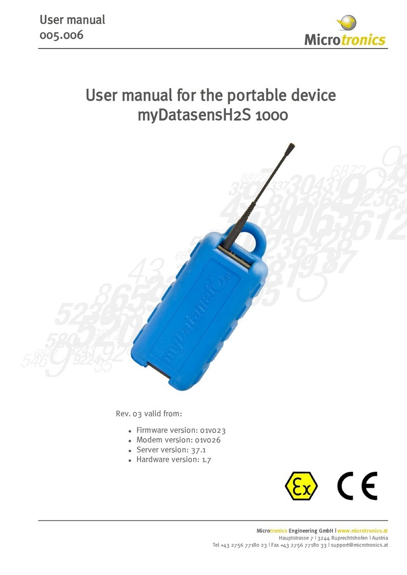
Microtronics myDatasensH2S 1000 User manual

300753 | Rev.05
Cover
Valid from:
lFirmware version: 01v026
lModem Version: 02v002
lServer version: 44.1
lHardware version: 4.0
User manual
myDatasensH2S 1000


Chapter 1 Table of contens
Cover 1
Chapter 1 Table of contens 3
Chapter 2 Declaration of conformity 9
Chapter 3 Ex certification 11
Chapter 4 Technical data 17
Chapter 5 General specifications 19
5.1 Translation 19
5.2 Copyright 19
5.3 General descriptive names 19
5.4 Ex protection 20
5.5 Safety instructions 21
5.5.1 Use of the hazard warnings 21
5.5.2 General safety instructions 21
5.5.3 Safety and preventative measures for handling GSM/GPRS modems 22
5.5.3.1 Safety and precautionary measures for the GSM/GPRS modem installation 22
5.5.3.2 Safety measures for installing the antenna 23
5.6 Overview 23
5.6.1 Block diagram 24
5.7 Intended use 24
5.8 General product information 25
5.9 Device labelling 25
5.10 Installation of spare and wear parts 26
5.11 Storage of the product 26
5.12 Obligation of the operator 27
Chapter 6 Functional principle 29
6.1 Determining the H2S concentration 30
6.1.1 Determining the raw value 31
6.1.2 Calculation of the calibrated H2S measurement value 32
Rev. 05 3

6.1.3 Calculation of the trimmed H2S measurement value 32
6.1.4 Digital filter 33
6.1.5 Alarm module 33
6.1.6 Record module 34
6.2 ALOHA transmission mode 35
6.3 Automatic selection of the GSM network 35
6.3.1 Ban list 36
Chapter 7 Storage, delivery and transport 37
7.1 Inspection of incoming deliveries 37
7.2 Scope of supply 37
7.3 Storage 37
7.4 Transport 38
7.5 Return 38
Chapter 8 Installation 39
8.1 Dimensions 39
8.2 Installing the myDatasensH2S 1000 40
8.2.1 Wall mounting 41
8.2.2 Suspended installation 43
8.3 Electrical installation 44
8.3.1 Connecting the GSM antenna 44
8.3.1.1 Optimum antenna positioning for assembly in a shaft 45
8.3.1.1.1 Typical influences on the signal quality 45
8.3.1.1.2 Possibilities for improving the signal quality 45
8.3.1.1.3 Procedure for determining the optimum position of the antenna 45
8.3.2 Technical details about the SIM slot 46
8.3.3 Technical details about the USB interface 46
Chapter 9 Initial Start-Up 49
9.1 User information 49
9.2 General principles 49
9.3 Placing the system into operation 49
4Rev. 05

Chapter 1 Table of contens
9.4 Testing communication with the device 51
Chapter 10 User interfaces 53
10.1 User interface on the myDatasensH2S 1000 53
10.1.1 Operating elements 53
10.1.1.1 Solenoid switch 53
10.1.1.2 Status LED 54
10.2 User interface on the myDatanet-Server 55
10.2.1 Site configuration 55
10.2.1.1 Site 55
10.2.1.2 Comments 55
10.2.1.3 Measurement channels 56
10.2.1.3.1 Basis 56
10.2.1.3.2 Alarms 56
10.2.1.3.3 Cross sensitivity of the H2S sensor 57
10.2.1.4 Calculated channels 57
10.2.1.4.1 Basis 57
10.2.1.4.2 Calculation 59
10.2.1.4.3 Alarms 61
10.2.1.5 Internal channels 61
10.2.1.5.1 Basis 61
10.2.1.5.2 Alarms 61
10.2.1.6 Alarm settings 62
10.2.1.7 Basic setting 63
10.2.1.8 FTP export settings 64
10.2.2 Device configuration 64
10.2.2.1 Comments 64
10.2.2.2 Measurement instrument 64
10.2.2.3 Device-specific settings 66
10.2.2.4 GPRS 66
Chapter 11 myDatanet server 67
Rev. 05 5

11.1 Overview 67
11.1.1 Explanation of the symbols 67
11.2 "Customer" area 68
11.3 "Site" area at customer level 70
11.3.1 Reports 71
11.3.2 Groups 71
11.3.3 Map view 71
11.4 Recommended procedure 71
11.4.1 Creating the site 71
11.4.2 Assigning a device to the customer 73
Chapter 12 DeviceConfig 75
12.1 General 75
12.2 Prerequisites 75
Chapter 13 API 77
13.1 General 77
13.2 rapidM2M Playground 77
13.2.1 Übersicht 78
Chapter 14 Maintenance 79
14.1 General maintenance 79
14.2 Accu or battery pack 79
14.3 Replacing the rechargeable battery or battery pack 80
14.3.1 Charging the accu pack 83
14.3.2 Replacing the rechargeable battery cover 85
14.3.3 Maintenance of the rechargeable battery seal 87
14.4 Maintenance of the antenna socket (not necessary from hardware version 4.0 onwards)
88
14.5 Maintenance of the antenna connector (only for antennas supplied before 09/2013) 89
14.6 Maintenance of the H2S sensor 90
14.6.1 Calibration, trimming and zero-point alignment 90
14.6.1.1 Safety instructions for handling H2S gas 91
6Rev. 05

Chapter 1 Table of contens
14.6.1.2 Calibration 91
14.6.1.2.1 Calibration specifications 91
14.6.1.2.2 Calibration room equipment 92
14.6.1.2.3 Calibration process 92
14.6.1.3 Trimming 98
14.6.1.4 Zero-point alignment 102
Chapter 15 Removal/disposal 105
Chapter 16 Troubleshooting and repair 107
16.1 General problems 107
16.2 Log entries and error codes 109
16.2.1 Modem error 114
16.3 Evaluating the device log 117
16.3.1 Evaluating the device log on the myDatanet server 117
16.3.2 Evaluating the device log using DeviceConfig 117
Chapter 17 Spare parts and accessories 119
17.1 Assembly sets 119
17.2 Antennas 119
17.3 Rechargeable battery and battery packs 119
17.4 Charging device 119
17.5 Cable 120
17.6 Other accessories 120
Chapter 18 Document history 121
Chapter 19 Glossary 125
Chapter 20 Contact information 127
Rev. 05 7


Chapter 2 Declaration of conformity
Rev. 05 9


Chapter 3 Ex certification
Rev. 05 11

12 Rev. 05

Chapter 3 Ex certification
Rev. 05 13

14 Rev. 05

Chapter 3 Ex certification
Rev. 05 15

16 Rev. 05

Chapter 4 Technical data
Voltage
supply
BP457A battery : 51Ah
AP424DA rechargeable battery : 19,2Ah
lUi: 6V
lIi: 1,7A
lPi: 6,97W
lLi: 0
lCi: 780µF
Housing Material: Noryl GTX 973
Weight: 450g (without rechargeable battery or battery pack)
Protection class: IP66
Dimensions (WHD): 100 x 240 x 100mm(without antenna)
Ex
certification II 2G Ex ib IIB T4 Gb
Operating
temperature
-10...+40°C
Air humidity 15...90%rH non-condensing
Storage
temperature
-20...+70°C (without rechargeable battery or battery pack)
Display LED for indicating the operating state and error codes
Operation Solenoid switch for initiating ALOHA transmission mode
USB
interface
1 x USB slave for establishing a connection to a PC. The DeviceConfig configuration
program must be installed on the PC to enable communication with the
myDatasensH2S 1000 .
Additional information is provided in "Technical details about the USB interface" on
page 46.
Antenna
connector
FME-M
H2S sensor Measurement range: 0-200ppm
Max. overflow: 1000ppm
Resolution: 0,25ppm
Pressure range: Atmospheric +/-10%
T90 response time: <=35s
Calibration cycle: 6 months
Max. service life: 2 years
Repeat accuracy: 1%
Rev. 05 17

Temperature
sensor
Measurement range: -10...+40°C
Resolution: 0,1°C
Data
memory
Internal flash memory for up to 125.771 measurement values
Data type s16 (16 signed)
Data
transmission
By means of GSM/GPRS quad-band modem to the relevant myDatanet server
SIM Integrated SIM chip and SIM slot for external SIM card
Additional information is provided in "Technical details about the SIM slot" on page
46.
Monthly
data volume
3,88MB at two-minute measurement cycle and 120-minute transmission cycle
Device
operating
time
BP457A battery :
lApprox. 2 years with two-minute measurement cycle and 120-minute
transmission cycle
lApprox. 2,2 years with five-minute measurement cycle and 120-minute
transmission cycle
lApprox. 4 years with five-minute measurement cycle and 480-minute
transmission cycle
AP424DA rechargeable battery :
lApprox. 0,9 years with two-minute measurement cycle and 120-minute
transmission cycle
lApprox. 1 year with five-minute measurement cycle and 120-minute
transmission cycle
lApprox. 2 years with five-minute measurement cycle and 480-minute
transmission cycle
18 Rev. 05

Chapter 5 General specifications
The information in this manual has been compiled with great care and to the best of our knowledge.
The manufacturer, however, assumes no liability for any incorrect specifications that may be
provided in this manual. The manufacturer is not responsible for direct, indirect, accidental or
consequential damages which arise from errors or omissions in this manual even if advised of the
possibility of such damages. In the interest of continuous product development, the manufacturer
reserves the right to make improvements to this manual and the products described in it at any time
and without prior notification or obligation.
Note: The specifications in this manual are valid as of the versions listed on the front page. Revised versions of this
manual, as well as software and driver updates are available in the service area of the myDatanet server.
5.1 Translation
For deliveries to countries in the European Economic Area, the manual must be translated into the
language of the respective country. If there are any discrepancies in the translated text, the original
manual (German) must be referenced or the manufacturer contacted for clarification.
5.2 Copyright
The copying and distribution of this document as well as the utilisation and communication of its
contents to others without express authorisation is prohibited. Contraventions are liable to
compensation. All rights reserved.
5.3 General descriptive names
The use of general descriptive names, trade names, trademarks and the like in this manual does not
entitle the reader to assume they may be used freely by everyone. They are often protected
registered trademarks even if not marked as such.
Rev. 05 19

5.4 Ex protection
The portable measurement instrument myDatasensH2S 1000 designed for use in areas with a zone1
explosive atmosphere.
The following conditions must be adhered to:
lOnly the manufacturer is permitted to open the housing to carry out maintenance work, which
must only be completed outside the Ex area.
lIt is permissible to replace the rechargeable battery pack in the Ex area, although it must not
be charged there. Please note that if the seal is broken on devices with a maintenance
contract, this will render the contract void.
lThe rechargeable battery pack must only be charged outside the Ex area only using the
charging device tested and approved by the manufacturer (see "Charging device" on page
119).
lThe power supply in the Ex area must only be provided by the designated, intrinsically safe
rechargeable battery or battery packs (see "Rechargeable battery and battery packs" on page
119).
lThe USB interface must NOT be used in the Ex area.
lThe SIM card must NOT be replaced in the Ex area.
lOnly the antenna, tested and approved by the manufacturer, with or without an antenna
extension, tested and approved by the manufacturer, may be connected to the antenna
connector (see "Antennas" on page 119).
II 2G Ex ib IIB T4 Gb
Important note: The Ex approval is only valid if the corresponding marking is provided on
the type plate of the measurement device .
Important note: The certificates of conformity and any relevant test certificates from the
respective authorities must be carefully observed during installation and commissioning.
1myDatasensH2S 1000
20 Rev. 05
Other manuals for myDatasensH2S 1000
1
Table of contents
Other Microtronics Measuring Instrument manuals

Microtronics
Microtronics myDatasensH2S 1000 User manual

Microtronics
Microtronics myDatalogEASY IoTmini User manual

Microtronics
Microtronics 300336 User manual

Microtronics
Microtronics Blue Force User manual
Microtronics
Microtronics myDatalogEASYmbm User manual

Microtronics
Microtronics BLUEFORCE SMART PRO User manual
Microtronics
Microtronics rapidM2M T32x User manual